1
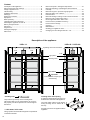
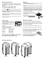
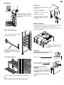
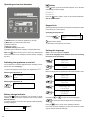
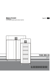
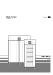
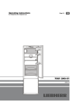
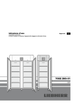
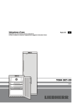
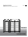
Operating instructions
Refrigerator
Read the operating instructions before switching on for the first time
Page 16
GB
7084 683-00
LKPv
Content
Description of the appliance.................................................... 16
Safety instructions and warnings............................................ 17
Range of appliance use........................................................... 18
Climate rating.......................................................................... 18
Appliance dimensions............................................................. 18
Setting up................................................................................ 18
Electrical connection............................................................... 18
Equipment............................................................................... 19
Back-up battery....................................................................... 19
Operating and control elements..............................................20
Switching the appliance on and off.........................................20
Battery charge indicator..........................................................20
Set button................................................................................20
Keypad lock.............................................................................20
Setting the language...............................................................20
Main menu............................................................................... 21
Menu 01 Setpoint = setting the temperature........................... 21
Menu 03 Defrosting = activating the defrost function
manually.................................................................................. 21
Menu 04 Program = preset storage programs......................... 21
Menu 05 Alarm = list of alarms................................................22
External alarm.........................................................................22
Menu 06 Settings= settings on the control electronics...........23
Menu 07 Light = interior light control.......................................25
Interior light LKPv 6523 / LKPv 1423.......................................25
Product sensor (available accessory).....................................25
Product sensor settings ..........................................................26
Cleaning..................................................................................27
Malfunctions............................................................................27
Shutting your appliance down.................................................27
Changing over door hinges LKPv 65.. / 84..............................28
Description of the appliance
LKPv 65.. / LKPv 84..
LKPv 14..
Operating and control elements
Lock
Lock
Lock
Type plate**
Stacking mark*
Grid shelves
Important
The maximum load per grid
shelf is 60 kg.
* Stacking mark
Only load the top shelf up to the stacking mark.
This is important so as to ensure that the air can circulate properly and the temperature is even throughout
the interior.
** LKPv 6523 / LKPv 1423
The type plate is located in the refrigerator compartment
on the left-hand side.
16
Cleaning water drain opening
A drain hose with an R 3/4 connection can
be fitted to the underside of the appliance.
The water which collects in the interior
during cleaning can be drained off in
this way.
An angled connector is supplied with the
appliance.
Safety instructions and warnings
•To prevent injury or damage to the unit, the appliance should be unpacked and set up by two
people.
•In the event that the appliance is damaged on
delivery, contact the supplier immediately before
connecting to the mains.
•To guarantee safe operation, ensure that the appliance is set up and connected as described in
these operating instructions.
•Disconnect the appliance from the mains if any
fault occurs. Pull out the plug, switch off or remove
the fuse.
•When disconnecting the appliance, pull on the
plug, not on the cable.
•Any repairs and work on the appliance should
only be carried out by the customer service
department, as unauthorised work could prove
highly dangerous for the user. The same applies
to changing the mains power cable.
•Do not allow naked flames or ignition sources
to enter the appliance. When transporting and
cleaning the appliance, ensure that the refrigerant
circuit is not damaged. In the event of damage,
make sure that there are no ignition sources
nearby and keep the room well ventilated.
•Do not stand on the plinth, drawers or doors or
use them to support anything else.
•This appliance can be used by children of 8 years
old and over, and also by persons with restricted
physical, sensory or mental capacity or lack of
experience and knowledge, if they are supervised
or have been instructed on safe use of the appliance and understand the resulting risks. Children
must not be allowed to play with the appliance.
Cleaning and user maintenance must not be
carried out by children without supervision.
•Avoid prolonged skin contact with cold surfaces or
chilled/frozen food.This could cause pain, numbness and frostbite. In the case of prolonged skin
contact, protective measures should be taken,
e.g. gloves should be worn.
GB
•Do not store explosives or sprays using combustible propellants such as butane, propane,
pentane, etc. in the appliance. Electrical components might cause leaking gas to ignite. You
may identify such sprays by the printed contents
or a flame symbol.
•Do not use electrical appliances inside the appliance.
•If you have a lockable appliance, do not keep the
key near the appliance or within reach of children.
•The appliance is designed for use in enclosed
areas. Do not operate the appliance outdoors or
in areas where it is exposed to splash water or
damp conditions.
• Do not install the appliance in the immediate
vicinity of an air-conditioning unit. The appliance should also not be operated under a wallmounted air-conditioning unit.
•The appliance is not suitable for storing drugs
pursuant to DIN 58345.
•The appliance is not suitable for storing blood
bottles pursuant to DIN 58371.
•In special fields of application which are subject
to their own standard, the user is responsible for
complying with this standard.
LKPv 6523 / LKPv 1423
•When transporting or operating the appliance at
an altitude of more than 1500 m above sea level,
the glass pane in the door can break due to the
reduction in air pressure. Broken fragments are
sharp-edged and can cause serious injury.
•The LED light strip illuminates the interior of the
appliance. It is not suitable for lighting a room.
Noise emissions from the appliance
The noise level while the appliance is operating is below 70 dB(A)
(relative noise level 1 pW).
•Do not consume food which has been stored for
too long, as it could cause food poisoning.
17
Range of appliance use
The appliance is suitable for storing and cooling laboratory preparations at temperatures of
between
-2°C and +16°C (LKPv 6520, 1420),
0°C and +16°C (LKPv 6523, 1423).
The appliance is not suitable for use in explosion-hazard areas.
For the storage of valuable or temperature-sensitive substances
or products the use of an independent, constantly monitoring
alarm system is necessary.
This alarm system must be designed so that each alarm status
is detected immediately by an authorised person who can then
take appropriate action.
Position the temperature sensor for this system in the upper part
of the interior container.
The climate rating indicates the room
temperature at which the appliance may
be operated in order to achieve full refrigeration performance.
The climate rating is indicated on the
type plate.
The position of the type plate is shown in the section entitled
Description of the appliance.
4 (SN)
4 (N)
4+ (ST)
4+ (SN-ST)
5 (T)
5 (SN-T)
• Avoid positioning the appliance in direct sunlight or near cookers,
radiators and similar sources of heat.
• The floor on which the appliance stands should be horizontal
and level.
• Standard EN 378 specifies that the room in which you install
your appliance must have a volume of 1 m3 per 8 g of R 290a
refrigerant used in the appliance, so as to avoid the formation of
inflammable gas/air mixtures in the room where the appliance is
located in the event of a leak in the refrigerant circuit.The quantity
of refrigerant used in your appliance is indicated on the type plate
on the inside of the appliance.
• There must be a gap of at least 30 cm
between the upper edge of the appliance
and the ceiling.
Do not cover ventilation openings or grille.
Electrical connection
Climate rating
Climate rating
Setting up
Room temperature
+10°C to +32°C
+16°C to +32°C
+16°C to +38°C
+10°C to +38°C
+16°C to +43°C
+10°C to +43°C
Only operate the appliance with alternating current (AC).
The permissible voltage and frequency are indicated on the type
plate. The position of the type plate is shown in the section entitled
Description of the appliance.
The socket must be properly earthed and protected by a fuse.
The tripping current of the fuse must be between 10 A and 16 A.
The socket must not be situated behind the appliance and must be easily accessible.
Do not connect the appliance using an extension cable or extension socket.
Do not operate the appliance outside the
specified room temperature range.
Do not use stand-alone inverters (conversion
of direct current to alternating/three-phase
current) or energy-saving plugs. Risk of damage to the electronic control system!
Appliance dimensions
LKPv 65..
18
LKPv 84..
LKPv 14..
GB
Equipment
Safety lock
The lock is equipped with a safety
mechanism.
Locking the appliance
Suspend the rails at the desired
height, by inserting into the rear
clip-in strip first and then clipping
in at the front.
• Insert the key as shown by arrow 1.
• Turn the key 180° (2).
To unlock the appliance, the same
procedure must be repeated in the
same order.
Back-up battery
Before the appliance is switched on, the battery which is fitted in
the compressor compartment must be connected.
LKPv 1490 equipment
This battery ensures that alarms are always reported, even in the
event of a power failure.
Fit the supplied shelf rails to the right
and left of the vertical bar.
The battery is fitted in the compressor compartment at the top of the
appliance.
Suspend the rails at the desired
height, by inserting into the rear
clip-in strip first and then clipping in
at the front.
Important!
Intermediate shelves
Remove cover.
The appliance must not be connected to
the electrical power supply yet.
Plug the connector onto the positive
pole on the battery.
Disposal instructions for
batteries
The battery must be removed when
you wish to dispose of the appliance
and sent for separate waste treatment
for batteries.
Place the supplied intermediate shelves onto the shelf rails.
Do not damage or short circuit the
battery.
Note
The maximum load per intermediate shelf is 20 kg.
19
Operating and control elements
button
If the
button is pressed in standard display mode, the date
and time appear in the display.
DD/MM/YY
hh:mm:ss
Press the
button again to return to the standard indication.
This is not automatic.
Keypad lock
The keypad lock ensures that no unintentional changes are made
to the electronic control system.
Activating the keypad lock
>
5 seconds
1ON/OFF button (to switch the appliance on and off)
2Menu button (to activate the main menu)
3Selection buttons
4Set button (Enter)
5Audible warning on/off button
6Display (above indication in display = standard indication)
Note: the
button can be used to cancel any unintentional
actions and return to the standard indication without changing
the value.
appears in the display.
To deactivate, press again for 5 seconds.
Setting the language
Note: The preset language is English.
If this is the language which should remain, the following
procedure is not necessary.
Switching the appliance on and off
You are advised to clean the appliance before switching it on for
the first time (see "Cleaning").
• Connect the appliance to the mains - the display reads OFF.
Switching the appliance on
>
Lab Cooler
Temp.
3 seconds
- - °C
OFF
Battery charge indicator
If the symbol appears in the display, it is necessary to check
whether the battery has been connected. See section entitled
Back-up battery.
In normal operation, the symbol also appears while the battery
is being recharged.
Lab Cooler
Temp.
20
- - °C
>
Menu 01
SetPoint
>
Menu 07
Light
Note:
Menu 07 only appears on appliances LKPv 6523 and LKPv 1423.
Switching the appliance off
>
General Purpose
Temp.
- - °C
>
Menu 06
Settings
>
Settings 01
Service
>
Settings 02
Language
>
Language
English
Use buttons
and
to select the desired language.
> All menus will now appear in the set language.
Press the
button to return to the standard indication.
If no button is pressed within 60 seconds, the electronic control
system switches back automatically.
GB
Main menu
Press the
button.
Use buttons
and
to select one of the menu items.
Menu 01
Menu 03
Defrosting = activating the defrost function manually
The appliance defrosts automatically.
If the door has been left slightly open for a long time, a layer of
ice may form in the interior and on the cooling plate.
Setpoint = setting the temperature
Menu 03
The defrost function can then be activated manually.
Defrosting = activating the defrost function manually
Menu 04
>
Menu 01
SetPoint
Menu 05
>
Menu 03
Defrosting
Program = preset storage programs
Alarm = list of alarms
Menu 06
Settings = settings on the control electronics
>
(on LKPv 6523 and LKPv 1423 only)
Light = interior light control
Menu 07
Press button
Start Defrosting?
NoOk
to start defrosting or press the
cancel the procedure.
Menu 01
Setpoint = setting the temperature
>
>
Menu 04
Program = preset storage programs
Menu 01
Setpoint
New Set:
Current:
If the appliance is to be used for special purposes, different storage programs can be set.
The storage climate inside the appliance will then be adjusted to
the intended use (temperature, humidity).
-- ° C
-- ° C
The current temperature is then shown at the bottom of the display
and the required temperature is shown at the top.
Use button
to reduce the temperature = colder. Use button
to increase the temperature = warmer.
Press the
button to accept the new setting or the
to cancel the procedure without saving.
button to
button
>
Menu 01
Setpoint
>
Menu 03
Defrosting
>
Menu 04
Program
>
P16Set 5°C
Lab Cooler
Select the desired program by pressing the buttons
Press the
button to accept the new setting or the
to cancel the procedure without saving.
and
.
button
21
Menu 05 Alarm = list of alarms
The alarm events are saved and can be called up if required.
Calling up the saved alarm events
Thanks to an integrated battery, the electronic control system is
supplied with power, even in the event of a power failure, and the
alarm status is indicated immediately.
>
Menu 01
SetPoint
The audible warning signal sounds every time an alarm event
occurs.
>
Menu 06
Settings
>
Menu 05
Alarm
The audible warning signal can be cancelled by pressing button
.
> The last alarm which occurred is shown in the
The following alarm can be rectified immediately:
Door Open
Temp.
30 alarm events are saved.
- - °C
When the door is open, the above indication and the standard
indication flash alternately. After 60 seconds, the audible warning signal sounds.
Cancel the audible warning signal by pressing button
the appliance door.
. Close
The following alarm events require the stored items
to be checked:
1.
UPS activated
Temp.
display.
The highest figure (A _ _) is the last alarm which occurred.
Select a previous alarm event by pressing the buttons
>
>
>
This indication is displayed after a power failure.
Temp Room
2. High
Temp.
- - °C
Low
Door Open
DD/MM/YY
A01 E hh:mm
Door Open
DD/MM/YY
End of the alarm event with time and date.
The audible warning signal sounds.
Call up the length of the power failure and the maximum temperature reached inside the appliance. See chapter "Calling up the
saved alarm events".
.
Start of the alarm event with time and date.
- - °C
The above indication and the standard indication flash alternately.
A01 S hh:mm
and
A01 Door Open
Temp Max
- - °C
Highest temperature reached inside the appliance.
Return to the standard indication by pressing the
button.
Note
After this query, the alarm display will be deleted automatically.
Temp Room
Temp.
- - °C
The above indication and the standard indication flash alternately.
External alarm
This can be caused by:
• the appliance door being left open for a long time, allowing warm
ambient air to enter;
• a long power failure;
• a fault in the appliance.
A floating alarm contact and an RS485 interface are available.
The audible warning signal sounds.
If a large quantity of warm items is placed in the appliance at once,
this alarm may occur. This does not mean that there is an error.
Call up the length of the temperature rise and the maximum temperature reached inside the appliance. See chapter "Calling up
the saved alarm events".
In both cases, the items must be checked and it must be
decided if they can still be used.
All other alarms which occur must be rectified by a customer
service technician.
22
The appliance can be connected to an external alarm device.
A refitting kit for serial data evaluation via the RS485 interface is
available from your dealer or our customer service department.
The appliance may only be connected to an external alarm device by trained personnel!
GB
Menu 06 Settings
= settings on the control electronics
Settings 06
Display
Settings 01
Service
These settings can only be carried out by the customer service
department.
Settings 02
Language
Setting the display language. See paragraph "Setting the language".
Settings 03
Clock Setting
Setting the time and date.
Setting for permanent display light.
>
Menu 01
SetPoint
>
Menu 06
Settings
>
Settings 01
Service
>
Settings 08
Restore Offset
>
Menu 01
SetPoint
>
Settings 07
Calibration
>
Menu 06
Settings
>
Settings 06
Display
>
Settings 01
Service
>
D03 = 0
Backlight ON
>
Settings 02
Language
>
D03 = 0
0
>
Settings 03
Clock Setting
>
D03 = 0
1
>
Date: DD/MM/YY
Hour:hh:mm:ss
Save by pressing the
The value to be changed flashes and can be changed by pressing
the buttons
and
Save by pressing the
.
button.
Return to the standard indication by pressing the
button.
The display is now permanently lit.
button.
Return to the standard indication by pressing the
button.
The conversion from summer to winter time is not automatic.
Settings 04
Inputs/Outputs
These settings can only be carried out by the customer service
department.
Settings 05
Communication
This menu item is described in the documentation on the accessories set "Serial data evaluation".
23
Menu 06 Settings
Settings 07
Calibration
Adjustment of the displayed temperature to the actual interior
temperature.
Tolerances of temperature sensors can be offset with this function.
Adjustment is possible in three temperature ranges.
CAL1 = lower temperature range (approx. -2°C)
CAL2 = middle temperature range (approx. 5°C)
CAL3 = upper temperature range (approx. 16°C)
>
Menu 01
SetPoint
>
Menu 06
Settings
>
Settings 01
Service
>
Settings 08
Restore Offset
>
Settings 07
Calibration
>
>
(e.g. -1°C).
button.
CAL.1 Int temp
-1,0 ° C
0,0 ° C
° C flashes
>
CAL.1 Int temp
-1,0 ° C
0,0 ° C
The temperature correction value flashes and can be changed
using the buttons
Save by pressing the
Use button
or
.
button.
to proceed to CAL.2 and further to CAL.3 and
adjust the settings in the same way as for CAL.1.
Return to the standard indication by pressing the
24
Menu 06
Settings
>
Settings 01
Service
>
Einstellungen 08
Restore Offset
Restore Offset
NO
OK
to set the temperature correction values for
button.
Return to the standard indication by pressing the
The temperature range display flashes and can be changed using
Save by pressing the
>
without any changes by pressing the
CAL.1 Int temp
-2,0 ° C
0,0 ° C
or
Menu 01
SetPoint
Press button
the buttons
>
CAL1, CAL2 and CAL3, respectively, to 0 or cancel the procedure
° C flashes
>
Setting the temperature correction values to 0.
>
CAL.1 Int temp
-2,0 ° C
0,0 ° C
Settings 08
Restore Offset
button.
button.
Menu 07 Light
Product sensor (available accessory)
= interior light control
Note
This function is only active on appliances LKPv 6523 and
LKPv 1423.
>
Menu 01
SetPoint
>
Menu 07
Light
>
Use buttons
The temperature may be measured or recorded at any point in
the interior using the product sensor.
Remove the plug!
1.
Feed the sensor through the opening
in the compressor compartment
and position inside the appliance.
Seal the opening
with sealant.
New:On
Current:On
and
GB
to select the desired setting.
On = interior light permanently lit.
Door = interior light is switched on when the door is opened
and is switched off when the door is closed.
Off = interior light switched off.
Press the
button to accept the new setting or the
to cancel the procedure without saving.
button
2.
Undo the screw on the underside
of the front panel. Tilt the front
panel upwards.
Interior light
LKPv 6523 / LKPv 1423
The interior light is fitted on the inside at
the top.
The light intensity of the LED light corresponds to laser class 1/1M.
3.
Plug in the product sensor
plug.
Important
The light cover may only be removed
by customer service staff.
If the cover is removed, do not look
directly at the light through optical
lenses from close distance.
This can damage your eyes.
4.
Close the front panel and fix with the screw.
25
Product sensor settings
• Connect the appliance to the mains - the display reads OFF.
>
Lab Cooler
Product
Adjusting the alarm delay
- - °C
>
Menu 01
SetPoint
>
Menu 06
Set up
>
Settings 01
Service
>
Settings 09
Alarm setting
>
Sensor check
OFF
button.
The sensor is now monitored by the electronic control system. In
the event of a sensor error, an alarm will be signalled.
A12=
- 45 °C
- 45 °C
button.
A13=
45 °C
P high Alarm
>
A13=
and
Save by pressing the
flashes
to select the desired setting.
>
Use buttons
45 °C
45 °C
flashes
to select the desired setting.
button.
If an alarm delay needs to be set, carry out the steps in the next
section or return to the default display by pressing the
26
date/time using the
button.
button.
button.
>
Lab Cooler
Product
- - °C
>
Lab Cooler
Temp.
- - °C
>
Temp.
Product
- - °C
- - °C
>
Adjusting the alarm limits
>
to select the desired setting.
button.
When in standard display mode, it is possible to switch between
flashes
A12=
- 45 °C
P low Alarm
flashes
product sensor, standard temperature sensor, both sensors and
Sensor check
ON
>
and
0 Min.
0 Min.
Note
>
Save by pressing the
A14=
Return to the standard indication by pressing the
flashes
and
>
Save by pressing the
Sensor check
OFF
Use buttons
A14=
0 Min.
P Alarm Delay
Use buttons
>
Save by pressing the
>
DD/MM/YY
hh:mm:ss
Cleaning
Clean the appliance at least twice per year.
Before cleaning always switch off the appliance. Pull out
the mains plug or switch off or unscrew the fuse.
• Empty the appliance and store the food in a cool place.
• Clean the inside and equipment with lukewarm water and a little detergent. Do not use abrasive or acid cleaners or chemical
solvents.
Do not use steam cleaners because of the
risk of injury and damage.
• Ensure that no cleaning water penetrates into the electrical
components or ventilation grille.
• Dry all parts well with a cloth.
• Use a commercially available stainless-steel cleaning agent for
stainless-steel appliances.
Do not use abrasive sponges or scourers, do not use concentrated cleaning agents and never use cleaning agents
containing sand, chloride or acid or chemical solvents, as
these would damage the surfaces and could cause corrosion.
Cleaning the dust filter
Clean the dust filter at least twice
per year!
Remove the plug!
1. Remove the dust filter by
lifting upwards.
2. Clean the dust filter with
water and detergent.
GB
Malfunctions
You may be able to rectify the following faults by checking
the possible causes yourself:
• Appliance does not function:
–Is the appliance switched on?
–Is the plug correctly fitted in the mains socket?
–Is the fuse intact?
• The temperature is not low enough:
–Is the temperature setting correct (see "Setting the temperature")?
– Does the separately installed thermometer show the correct
reading?
– Is the ventilation system working properly?
– Is the appliance set up too close to a heat source?
If none of the above causes
apply and you cannot rectify
the fault yourself, contact the
nearest customer service department stating the type designation  , service number
and appliance number
as
indicated on the type plate.
1
2
3
The position of the type plate is shown in the section entitled
Description of the appliance.
Shutting your appliance down
If your appliance is to be shut down for any length of time, switch
it off and disconnect the plug or switch off or unscrew the fuse.
Clean the appliance and leave the door open in order to prevent
unpleasant smells.
The appliance complies with the relevant safety regulations and
EC Directives 2004/108/EC and 2006/95/EC.
3. Reinstall the dust filter.
27
Changing over door hinges LKPv 65.. / 84..
Door hinges should only be changed by a trained expert.
Changing the door hinges must be done by two people.
4.Remove the hinge components from the hinge bracket.
Bearing ring
Brass washer
Hinge bushing
1.Open door by about 90°.
Important note
The door must be opened 90°
before the lower hinge bracket
is removed.
This will hold the self-closing
mechanism that is integrated into
the door in the required position for
installation.
Plastic washer
Note on point 4
The hinge bushing with brass washer and bearing ring may stick in the door mounting when
you pull out the hinge bracket and, in this case,
must be removed from it.
WARNING!
If the door is removed and reinstalled in the
closed position, this will lead to destruction of
the self-closing mechanism on the first opening of the door.
Important
As a result of its heavy weight, the door
must be held secure by one person.
2.Remove hinge bracket.
Pull the door out at the
bottom and lift off.
5.Transfer the upper hinge bracket and covers to the
opposite side.
6.Turn the door by 180°.
3.Remove bearing ring from
upper door mounting.
7.Insert the bearing ring and
hinge bushing in the upper
door mounting.
28
GB
8. Unscrew base mounting bracket and
attach on the other side.
11.Install the hinge bracket with the fitted
hinge components in the lower door
mounting.
9.Keeping door open at 90°, suspend
in top square pin.
WARNING!
It is essential that the door is
open at an angle of 90° during
installation.
If the door is installed in the
closed position, this will lead to
destruction of the self-closing
mechanism on the first opening
and closing of the door.
Note on point 11
The tabs on the bearing ring must fit into
the recesses of the door mounting during
installation.
If necessary, gently rotate the upper ring.
Important
As a result of its heavy weight, the door
must be held secure by one person.
10.Fit the hinge components on the hinge bracket.
Bearing ring
Brass washer
Plastic washer
12.Screw hinge bracket into place.
29