1
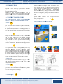
FIAMM Standby Batteries
Installation & Operating Instruction -Technical Manual
Edition 06/2013 - EMEA
TABLE OF CONTENTS
INTRODUCTION
CONSTRUCTION FEATURES
SAFETY
♦
Protective Equipment
♦
Battery disposal
♦
Plates
♦
Containers
♦
Separators
♦
Electrolyte
♦
Battery care
♦
Vent Plugs
♦
Cleaning
♦
Terminal post
♦
Voltage checks
♦
Specific gravity reading
OPERATING FEATURES
♦
Cell Appearance
♦
Capacity
♦
Pilot Cell
♦
Capacity in relation to discharge rate
♦
Periodic Inspections
♦
Capacity range of FIAMM Flooded Lead Acid
MAINTENANCE
Batteries
BATTERY TEST
♦
Capacity in relation to the temperature
APPLICABLE STANDARDS
♦
Internal impedance and short circuit current
♦
Storage of filled and charged cells
♦
Storage of dry charged cells
♦
Service life
♦
Gassing
♦
Operation of batteries in parallel
♦
Electrolyte Specific Gravity - State of charge
COMMISSIONING CHARGE / FIRST
CHARGE
♦
Dry charge cells
♦
Filled and Charged Cells
CHARGING
♦
Floating charge
♦
Boost charge (Recharge following a discharge)
♦
Equalize voltage
BATTERY INSTALLATION
♦
Installation
♦
Battery room requirements
Page 2 of
This document and the confidential information it contains shall be distributed, routed or made available solely with written permission of FIAMM. FIAMM
S.p.A. reserves the right to change or revise without notice any information or detail given in this publication.
2
FIAM
MM Standby Ba
atteries
Installation & Operating Instruction -Technical Manual
INTROD
DUCTION
Inn a high tecchnological environment
e
it is extrem
mely
im
mportant to have a backkup power source
s
wheneever
p
possible.
In faact mains pow
wer failure couuld cause sevvere
loosses and dam
mages anytimee.
F
FIAMM
has been develloping througghout years of
reesearch and exxperience sevveral ranges off Absorbed Gllass
B
Batteries
(AGM
M) to ensure the
t best reliability and qualiity.
CONSTR
RUCTION
N FEATURE
ES
The main coonstruction features
T
f
of FIAMM AG
GM
b
batteries
are shortly
s
described in the beelow section.
♦ Plates
Edition 06//2013 - EMEA
Suitable threaaded post dessign (‘male’ or ‘female’ pole)
p
with solid coonnectors are provided to ensure
e
low ohhmic
losses. Post to
t lid seals arre designed to
o prevent leakkage
over a wide range
r
of internnal pressures and conditionns of
thermal cycliing. Intercell connections in the FIA
AMM
multicell AG
GM battery ddesign are electrically weelded
through the cell walls to m
minimise the in
nternal impedance
while maintaiining complette separation of the indiviidual
cells.
Special plasstic terminaal caps aree provided for
transportationn assuring a pprotection agaainst short cirrcuit
during transpoortation.
F
Cutaway draawing of FIAM
MM AGM ceell
A
Both positive and negativee plates are of
B
o the flat passted
tyype. The activve material is made of a passte of lead oxiide,
w
water,
sulphuriic acid and otther materials needed to obttain
thhe performannces and stabbility requiredd throughout the
b
battery
life. The
T grids are made of a high
h
quality lead
a
alloy
with calccium and tin which
w
assuress good resistaance
a
against
corrosiion
♦ Containers
E
D
C
B
D
Battery cases and
B
a lids are made
m
of a typpe of ABS whhich
c
complies
with American Staandards UL 94,
9 class V-0 and
w
with
IEC 7077, method FV0.
F
This material
m
is shoock
reesistant and flame
f
retardannt. They are also designedd to
fu
fully
withstannd the internaal pressure variations
v
durring
b
battery
operatiion. This is further
f
ensureed by reinforrced
c
container
wallss and lids. Haandles have been
b
designed for
some batteries into the lids to
t facilitate haandling.
♦ Separatorss
A
B
C
The separatorss are made of
T
o glass microofibre mats by a
sppecial processs which resultts in a high poorosity with very
v
sm
mall pore diameters
d
to ensure maaximum oxyggen
d
diffusion
whilee maintainingg high plate uttilisation and low
l
innternal resistaance. The plattes are compleetely wrappedd by
thhe separator and
a the electroolyte is compleetely absorbedd in
thhe separator and
a plates. Byy this method,, the sheddingg of
a
active
materiaal which durring the batttery life cauuses
shhorting with flooded
f
batteryy constructionn is avoided.
F
E
Female (B
Bolt) terminal
F
E
Ma
ale Terminal
♦ Electrolytee
The electrolyte is sulphuricc acid of 1.3 sp. gr. at 200°C
T
w
with
same purity characterristics as otheer types of hhigh
q
quality
lead accid batteries.
♦ Valves
D
Each cell has a one way valve
E
v
to perm
mit the releasee of
g
gases
from the
t
cell wheenever the innternal presssure
e
exceeds
the fixed
f
safety value.
v
The valve
v
is ratedd at
0
0.15~0.30
atm
mospheres (15~
~30 Kpa).
♦ Terminal posts
p
E
Page 3 off
Th
his document and the
t confidential info
ormation it contains
s shall be distribute
ed, routed or made available solely witth written permissio
on of FIAMM. FIAMM
S.p.A. reserves the right to change or re
evise without notice
e any information or
o detail given in this
s publication.
3
FIAMM Standby Batteries
Installation & Operating Instruction -Technical Manual
Edition 06/2013 - EMEA
♦ Connections
Suitable solid connectors 1 are made of tin or lead
plated copper; suitable insulated plastic
covers
2 are
made of ABS -V0
2
From 5 to 10
mm
1
♦ Remote Venting System (RVS)
Most of FIAMM AGM batteries are designed with an
optional central degassing system on the top lid
covering sheet. So if batteries need to be installed in a
totally sealed cabinet, it is advisable to use the remote
venting system available from the manufacturer to
conduct any gas from the batteries to the outside of the
cabinet itself.
2
2
RVS – front side
used for FIT / UMTB range
5
RVS – top side
used for SLA / FLB / SP /
FIT / UMTB range
2
1
1
4
4
TOP TERMINAL CONNECTION is mainly used for
FIAMM battery range SLA – FLB – SP as well
♦ Front Terminal Connections
Suitable solid connectors made of copper thin or lead
plated and covers made of ABS are provided to make a
propper installation between blocs. Designed for
FIAMM front terminal range UMTB – FIT using a
special “L “ clamp
5
1 SOLID CONNECTOR
2 COVER
3 “L” CLAMP
3
Page 4 of
This document and the confidential information it contains shall be distributed, routed or made available solely with written permission of FIAMM. FIAMM
S.p.A. reserves the right to change or revise without notice any information or detail given in this publication.
4
FIAMM Standby Batteries
Installation & Operating Instruction -Technical Manual
♦ Capacity range of FIAMM AGM Lead Acid
Batteries
OPERATING FEATURES
♦ Capacity
The battery capacity is rated in ampere hours (Ah) and
is the quantity of electricity which it can supply during
discharge. The capacity depends on the quantity of the
active materials contained in the battery (thus on
dimensions and weight) as well as the discharge rate,
and temperature, and minimum voltage.
The nominal capacity of FIAMM batteries refers to the
10 hrs discharge rate (indicated with C10) with constant
current at 20°C to 1.80 volt per cell.
FIAMM
Battery range
UMTB
FIT
SLA
FLB
SP
Capacity range
[Ah]
from 60 to 160
from 40 to 180
from 25 to 2000
from 26 to 235
from 26 to 235
♦ Capacity in relation to the temperature
The capacity available from a battery, at any
particular discharge rate, varies with temperature.
Batteries which have to operate at temperatures
different from the nominal (20°C) need a higher or
lower capacity as per the factor indicated in the
following graph (required capacity has to be multiply
by the correction factor stated in the graph).
13
12.5
12
Bloc Voltage (Volt)
Edition 06/2013 - EMEA
11.5
11
I=0,088 C10
I= 0,1 C10
10.5
I= 0,15 C10
I= 0,27 C10
10
1.2
I=0,5 C10
I=0,85 C10
1.1
9
0
1
2
3
4
5
6
7
8
9
10
11
12
13
14
hours
Fig. 1: Typical discharge curves for FIAMM AGM batteries (FIT
range)
♦ Capacity in relation to discharge rate
The available capacity of all lead acid batteries depend
on discharge rate (discharge current); this is due to
internal electrochemical process and type of
construction (i.e. type of positive plate).
Temperature correction factor
9.5
1.0
0.9
15 -30 min. discharge rate
0.8
1-10 hours discharge rate
0.7
0.6
0.5
0.4
-20°C
-10°C
0°C
10°C
20°C
30°C
40°C
50°C
Temperature
120
Fig. 3: Capacity Correction factor versus temperature for a 10 hours
discharge rate for FIAMM Lead Acid AGM batteries
available capacity [%]
100
♦ Internal impedance and short circuit current
80
60
40
20
0
0
2
4
6
8
10
hours
Fig. 2: Average available capacity versus discharge rates for FIAMM
AGM batteries
The internal impedance of a lead acid battery is a
direct result of the type of internal construction, plate
thickness, number of plates, separator material,
electrolyte sp. gr., temperature and state of charge.
The internal resistance and the short circuit current of
FIAMM VRLA batteries at 100% state of charge and
20°C is indicated in the relative Product Sheet. These
values are calculated in accordance with IEC 60896
part 21/22.
Different instruments are available to detect the
internal resistance
or impedance of lead acid
batteries. These instruments use a different way to
determinate these values. The values obtained from
these instruments will be different to the values stated
in FIAMM Product Sheet.
Page 5 of
This document and the confidential information it contains shall be distributed, routed or made available solely with written permission of FIAMM. FIAMM
S.p.A. reserves the right to change or revise without notice any information or detail given in this publication.
5
FIAMM Standby Batteries
Installation & Operating Instruction -Technical Manual
♦ Service life
According to the main international standards a battery is
considered at the end of its service life whenever
delivering less than 80% of its nominal capacity. The
recommended operating temperature range is between
10°C to 30°C. FIAMM VRLA batteries can operate over
a temperature range of –20 to +50°C and higher;
operation at temperature higher than 20°C reduces life
expectancy according to the graph in figure 4.
Edition 06/2013 - EMEA
• in each string only cells or monoblocs of the same
type, model and quantity should be used;
• a symmetrical layout of the batteries should be
designed (i.e. length and type of connector) to
minimize possible resistance variations;
• the quantity of strings in parallel should be
reasonable in terms of layout and application.
Usually 4 strings could be connected in parallel.
However, depending on strings voltage and cables
length, a higher number of strings could be safely
connected to reach required total capacity.
120
♦ Open circuit voltage - State of charge
100
The measurement of the open circuit voltage (battery has
to be disconnect from charger system for at least 24
hours) provides an approximate indication of the state of
charge of the cells.
Battery Life (%)
80
2.15
60
40
20
0
20
30
40
50
Open Circuit Voltage [V/cell.]
2.10
2.05
2.00
TEMPERATURE [°C]
Fig. 4: Expected service life vs working temperature
1.95
0%
20%
40%
60%
80%
100%
State of Charge [%]
♦ Gassing
All Lead Acid Batteries emits gases during the charge
process. FIAMM VRLA batteries have a high
recombination efficiency (>98%) and for cells operated at
20°C under normal operating conditions venting is
virtually negligible. Laboratory test measurements show
the following gassing rates:
• 2 ml/Ah/cell/month at a float voltage of 2.27 V/cell
• 10 ml/Ah/cell/month at a recharge voltage of 2.40
V/cell.
The quantity of gas given off in the air (it basically
consists of 80-90% hydrogen) is very low and thus it is
clear that FIAMM VRLA batteries can be installed in
rooms containing electric equipment with no explosion
danger or corrosion problems under normal conditions. In
any case these rooms or cabinets must have a natural or
forced ventilation and not be fully sealed. Please refer to
“VENTILATION” for information on required air
exchange.
Fig. 5: Approximate state of Charge versus Open circuit cell voltage
♦ Operation of batteries in parallel
When the required capacity exceeds the capacity of a
single string of batteries, it is possible to connect more
strings in parallel paying attention to the following
guidelines:
Page 6 of
This document and the confidential information it contains shall be distributed, routed or made available solely with written permission of FIAMM. FIAMM
S.p.A. reserves the right to change or revise without notice any information or detail given in this publication.
6
FIAMM Standby Batteries
Installation & Operating Instruction -Technical Manual
limited to no more than once per month to ensure the
maximum service life of the battery.
RECHARGING
In order to ensure the best protection against power
failures in any moment, it is necessary that batteries are
kept in the following conditions:
♦ Floating charge
120%
100%
I=0.15 C10
Recharged Capacity [Ah]
• in float charging throughout all their standby period;
• fully recharged soon after a discharge,
• completely recharged after a discharge. Recharge as
soon as possible to ensure maximum protection
against subsequent power outages. Early recharge also
ensures the maximum battery life.
80%
I=0.10 C10
60%
I=0.05 C10
40%
20%
60
140
50
122
40
104
30
86
20
68
10
50
0
32
-10
14
-20
0%
0
5
10
15
20
Time [hours]
Fig. 7
Recharge curves at 2.4 volt per cell with different limit of current
Tempearture [°F]
Floating battery systems are those where the charger, the
battery and the load are connected in parallel.
The "float" setting will maintain the battery in a fully
charged state with minimal water consumption.
The voltage recommended for float charge is 2.27 V at
20°C. The recommended float voltages to maximise the
battery life over the range of temperatures between -20
and +60°C are shown in the figure 6.
The normal float current observed in fully charged
FIAMM front terminal batteries at 2.27 VPC and a
temperature of 20°C is approximately 0.3 mA/Ah.
Because of the nature of recombination phenomena, the
float current observed in the case of the FIAMM front
terminal batteries is normally higher than that of vented
batteries and is not an indication of the state of charge of
batteries
Temperature [°C]
Edition 06/2013 - EMEA
-4
2.19
2.21
2.23
2.25
2.27
2.29
2.31
2.33
2.35
Float Voltage [V/cell]
Fig. 6
Recommended Float Voltage at different temperatures
♦ Boost charge (Recharge following a discharge)
Boost charge has to be used to recharge a battery after a
discharge; it will restore the battery to a fully charged
state within a relatively short period of time. Use a
constant voltage 2.4 V/cell at 20°C with a maximum
current of 0.25 C10. However this recharge should be
Page 7 of
This document and the confidential information it contains shall be distributed, routed or made available solely with written permission of FIAMM. FIAMM
S.p.A. reserves the right to change or revise without notice any information or detail given in this publication.
7
FIAM
MM Standby Ba
atteries
Installation & Operating Instruction -Technical Manual
BATTER
RY INSTA
ALLATION
N
All necessary precaution must
A
m
be takenn when workking
w lead acidd batteries as per electricall risk, explosiives
with
g
gasses,
heavyy componennts, corrosivee liquids. Use
U
innsulated tools and wear prootective equipm
ment.
♦ Installation
FIAMM frontt terminal vaalve regulatedd recombinattion
F
b
batteries
can be fitted on staands or into caabinets. FIAM
MM
o
offers
a wide selection
s
of staands, from onne tier/one row
w to
six tiers/three rows, to suitt most appliccations. Cabinnets
a available with or witthout circuit breaker and its
are
reelevant compaartment.
1. Avoid anyy impact or shock whicch could caause
breaking or micro fractuures to contaiiner. Do not lift
cells by its terminals.
2 Make sure that all cell jars and coverrs are thorougghly
2.
clean and dry.
d
3 Synthetic cleaning
3.
c
clothss must not be used. Clean lids
l
and contaiiners only with
w
antistatic cotton clooths
soaked in a solution of
o mild soap and complettely
“wrung” ouut.
4 Should thee terminal possts have a whiite film on theem,
4.
lightly abbrade their contact surffaces, using a
Scotchbritee pad or fine grit
g abrasive paper,
p
to remoove
any surfacee oxidation.
5 Do not lift cells by term
5.
minals; do not use terminalss as
point of lift
fting during haandling/installlation process..
6 Place the single unitts at their correct posittion
6.
according to
t the electricaal layout.
7 In order to allow heat diissipation a minimum
7.
m
distaance
of 5-10mm
m between cells/blocs is reccommended; this
t
is normal using FIAM
MM standard connectors; for
special requuirements please contact FIIAMM .
8 Care must be taken to avoid
8.
a
short cirrcuiting the cells
h
with any off the battery hardware.
9 Start withh the lowestt shelf to ensure
9.
e
stabillity.
Carefully preserve
p
the sequence: poositive, negatiive,
positive, negative
n
throoughout the whole batteery.
Flexible caable connectoors for conneecting from one
o
shelf to thee one below, will
w be appliedd once that all the
blocs havee been conneected (we would
w
suggestt to
connect succh inter-shelff or inter-row cable connecttors
at the final User’s premises only).
10. To ensure a good eleectrical contaact between the
bottom of each
e
terminal and the connnecting strap and,
a
at the samee time, to ensuure that the thhreaded terminnals
are not daamaged by exxcessive torquue, use a torqque
spanner sett on the value of:
RANG
GE
TYPE
VALUE
E Nm VALUE Lb
bs
SLA-UMTB--FIT-FLB
M8 Female
F
10÷
÷12
88÷106
SLA
A
M10 Female
20÷
÷25
175÷22
20
FLB
B
M6 Female
F
7÷
÷9
62÷80
0
SLA-UM
MTB
M8 Male
7÷
÷8
65÷70
0
FIT-UM
MTB
6 Male
M6
5÷
÷7
44÷62
2
Edition 06//2013 - EMEA
11. Insulate all
a the connecctors by meaans of the plastic
covers beiing supplied w
with the batterry accessories..
12. Affix the cell number sstickers to thee cell jars maaking
sure that the
t surfaces aare dry and cllean. It is usual to
number thhe cells beginnning with #1 at
a the positivee end
of the batttery, numberring consecutiively in the same
s
order as thhe cells are coonnected electrrically, througgh to
the negativve end of the battery.
13. Check thee total batteryy voltage whicch should com
mply
with the tootal number of cell connectted in series.
14. The cellss are usuallyy designed to
o be installedd in
vertical poosition, the hoorizontal posittion could in some
s
cases streess the cells. Here below
w the correct cell
arrangemeents for large ccapacity AGM
M cells.
Examp
ple of installattion
and cell
c
arrangem
ment
(positiion of + / - polles)
of AG
GM batteries with
w
or
capaciity
equal
higherr than 800Ah
♦ Batteries installed intoo cabinet
For safety reeasons, we w
would not reccommend to preassemble the blocs into thhe cabinets beefore shipmennt to
the final Custtomer. Howevver, if this is normal practicee for
some system makers, we would strong
gly recommennd to
pay
p special attention
a
to prrotect the batttery system from
f
mechanical stress and vibrations occurring
o
duuring
transport. Forr this purpose, we would reequire to propperly
fasten all thee blocs to thhe relevant caabinet shelvess by
means of plaastic band annd/or other ad
dequate methhods.
Furthermore, the cabinet should be protected,
p
in the
outside, withh shock-absorbing packag
ging materiall, in
order to prevvent any trannsmission of vibrations too the
internal compponents such as the batteery blocs. Speecial
precautions
p
m
must
be takeen to avoid accidental short
s
circuits (do noot connect all the batteries, divide the batttery
circuit low vooltage parts).
For any furthher informatiion please reffer to EN500272
Standard or coontact FIAMM
M at: info.stan
[email protected]
♦ Ripple
Residual Ac ripple
r
is usuallly present in the
t output volltage
of chargers; amplitude
a
andd frequency deepends on chaarger
design and it can affect neggatively the battery
b
life. Riipple
could increaase water looss, battery temperature and
accelerate corrosion with a result to reeduce the batttery
life. It is recoommended theerefore, that voltage
v
regulaation
across the syystem includiing the load, but withoutt the
battery
b
conneected, under steady state conditions, shall
s
be
b better thann ± 1 throughh 5% to l00%
% load. Transsient
and other rippple type excuursions can be
b accommoddated
provided
p
thatt, with the batttery disconneected but the load
connected, thhe system peak to peak voltage,
v
including
the regulatioon limits, falls within
n 2.5% of the
recommendedd float voltaage of the baattery. Underr no
circumstances should the current flow
wing throughh the
Page 8 off
Th
his document and the
t confidential info
ormation it contains
s shall be distribute
ed, routed or made available solely witth written permissio
on of FIAMM. FIAMM
S.p.A. reserves the right to change or re
evise without notice
e any information or
o detail given in this
s publication.
8
FIAMM Standby Batteries
Installation & Operating Instruction -Technical Manual
battery when it is operating under float conditions,
reverse into the discharge mode.
♦ Battery room requirements
• The battery room should be dry, well ventilated and
have its temperature as moderate as the climate will
allow, preferably between 10°C and 30°C.
• DO NOT permit smoking or the use of open flames
in the battery room.
• Adequate ventilation to change the air in the battery
room is essential to prevent an accumulation of the
gases given off during charge (for further information
please refer to “VENTILATION” paragraph).
• The battery will give the best results and life when
working in a room temperature of 20°C, but will
function satisfactorily when operating in temperatures
between -20°C and +60°C. High temperatures
increase the performance, but decrease the life of the
cells; low temperatures reduce the performance.
• Do not allow direct sunlight to fall on any part of the
battery.
• If a rack is not supplied by FIAMM, suitable racks
should be provided to support the cells. These should
be arranged to provide easy access to each cell for
inspection, topping up and general maintenance.
Suitable racks may be made of wood or metal with a
coating of acid resistant paint. If metal racks are used,
they must be fitted with rubber or plastic insulators to
prevent the cells coming into contact with the metal.
• To facilitate proper battery operation, maintenance,
and care, post a battery data card/ instruction table in
a conspicuous place near the battery to provide the
attendant with service information and data.
•
•
•
•
•
•
•
•
Edition 06/2013 - EMEA
Batteries are no more dangerous than any other
equipment when handled correctly
Do not allow metal objects to rest on the battery or
fall across the terminals (even when disconnected, a
battery remain charged!).
Never wear rings or metal wrist bands when working
on batteries.
Do not smoke or permit open flames near batteries or
do anything to cause sparks.
Do not try to remove the battery cap to add water or
acid into the cell(s).
Never lift or pull up the battery at the terminals.
Air exchange must be provided to prevent the
formation of explosive hydrogen concentration.
For further information please refer to EN 50272-2
Safety requirements for secondary batteries and
battery installations Part 2: Stationary batteries.
♦ Battery Disposal
Lead acid batteries must be disposed according to the
country law. It is strongly recommended to send batteries
for recycling to a lead smelter. Please refer to the local
Standards for any further information, these batteries
need to be collected separately for wast disposal. As of
the 31st of December 1994, all Valve Regulated Lead
Acid (VRLA) battery has to have the following symbols
present in conformance to EG-guideline 93/86/EWG
SAFETY
It is recommended that full precautions be taken at all
times when working on batteries. The safety standards
of the country of installation must be risk, explosives
gasses, heavy components,
♦ Protective Equipment
Make sure that the following equipment is available to
personnel working with batteries:
• Instructions manual.
• Tools with insulated handles.
• Fire extinguisher.
• PPE (Personal Protective Equipment) must be worn
(glasses, gloves, aprons etc ... ). To avoid static
electricity when handling batteries, material of
clothing, safety boots and gloves are required to have
a surface resistance o ≤ 108 Ω, and an insulation
resistance ≥ 105 Ω
• First aid equipment must be available.
♦ Safety Precautions
Pb
SELECTION
STANDARDS
OF
APPLICABLE
FIAMM Valve Regulated Lead Acid Batteries
comply with:
• IEC 60896 –Part 21 Stationary lead-acid battery
Valve Regulated Type – Methods of tests;
• IEC 60896 –Part 22 S Stationary lead-acid battery
Valve Regulated Type - Requirements
• EN 50272-2 Safety requirements for secondary
batteries and battery installations Part 2: Stationary
batteries.
• BS 6290-4 Lead-acid stationary cells and batteries.
Specification for classifying valve regulated types.
• BS 6290-1 Lead-acid stationary cells and batteries.
Specification for general requirements
Observe the following precautions at all times:
Page 9 of
This document and the confidential information it contains shall be distributed, routed or made available solely with written permission of FIAMM. FIAMM
S.p.A. reserves the right to change or revise without notice any information or detail given in this publication.
9
FIAMM Standby Batteries
Installation & Operating Instruction -Technical Manual
Edition 06/2013 - EMEA
♦ Pilot Cell
MAINTENANCE
♦ Battery care
GASES GIVEN OFF BY BATTERIES ON CHARGE ARE
EXPLOSIVE!
DO NOT SMOKE OR PERMIT OPEN FLAMES OR DO
ANYTHING TO CAUSE SPARKS NEAR BATTERIES.
1. Keep the battery and surroundings clean and dry.
2. Make sure that bolted connections are properly
tightened (see table in INSTALLATION paragrapf).
3. Usually it is not necessary to apply greese on the bolts
and connectors, in any case "No-oxide" grease
increase the protection against corrosion.
4. Should any corrosion of the connections occur
because of spilled acid, etc., carefully remove
corrosion materials, thoroughly clean and neutralize
with diluted ammonia or baking soda.
5. Keep the battery at the recommended charge voltage
(see CHARGING section).
6. The room in which the battery is installed should be
well ventilated and its temperature as close as possible
to 20°C.
7. Do not try to open the cover valve.
♦ Cleaning
When necessary, batteries could be cleaned using a soft
dry antistatic cloth or water-moistened soft antistatic cloth
paying attention not to cause any ground faults.
No detergent nor solvent-based cleaning agents nor
abrasive cleaners should be used as they may cause a
permanent damage to the battery plastic container and lid.
For regular monitoring of the battery condition, select one
or more cells of the battery as a "pilot" cell(s); for
batteries comprising more than 60 cells, select one pilot
cell for every 60 cells.
♦ Periodic Inspections
Written records must be kept of battery maintenance, so
that long-term changes in battery condition may be
monitored. The following inspection procedures are
recommended:
EVERY SIX MONTHS:
• Visual inspection on cells/racks ( appearance,
cracks or corrosion signs, electrolyte leakage..),
• check and record the overall float voltage at the
battery terminals (not at the charger!),
• measure and record the pilot cell(s) voltage,
• measure and record the pilot cell(s) temperature,
• room ventilation.
YEARLY:
• all the controls indicated at six months,
• check and record the voltage of all cells,
• measure and record the pilot cell(s) temperature,
• make sure all connection are torque according to
connection torque table; in case of frequent high
discharge current please consider to check,
• clean the cells.
♦ Voltage checks
All voltage measurements should be made when the
whole battery has stabilized on floating, at least 7 days
after battery installation or after a discharge/ charge cycle.
To facilitate voltage reading in the correspondence of
each block terminal protection covers are designed with a
safe and proper hole. Measure and record individual
block voltages on float once a year. It is normal to have a
+0.2
spread of block voltages at 20°C up to 2.27
/-0.1 V
+0.54
(13.62
/-0.29 for a 12 volt battery) particularly in the
first year of operation. No corrective action is required in
this case. Maintaining a correct battery charging voltage
is extremely important for the reliability and life of the
battery. So it is advisable to carry out a periodical
checking of the overall float voltage to verify any
possible defect of charger or connections.
♦ Cell Appearance
Any cells showing corrosion, container bulging, high
temperature than the other cells, should be regarded as
suspect. Such cells should be carefully examined and,
expert advice should be obtained immediately from
FIAMM.
Page 10 of
This document and the confidential information it contains shall be distributed, routed or made available solely with written permission of FIAMM. FIAMM
S.p.A. reserves the right to change or revise without notice any information or detail given in this publication.
10
FIAMM Standby Batteries
Installation & Operating Instruction -Technical Manual
BATTERY TEST
Test must be conducted in accordance with EN 6089621/22.
Before any discharging test batteries have to be properly
prepared with a boost charge (2.4 volt per cell for 24
hours at 20°C) to ensure they are in a fully charge
condition. In order to take temperature readings of a
battery, one pilot cell or block shall be chosen. The
surface temperature of the container wall centre of each
pilot cell or block shall be measured immediately prior to
the discharge test. The individual readings shall be
between 15°C and 30°C. The temperature of the selected
block shall be considered as representative of the average
temperature of the battery. It is desirable that the average
cell surface temperature and the ambient temperature fall
as nearer to the reference temperature of 20°C or 25°C as
possible.
In case of batteries having a capacity lower than 80% of
the nominal rating it is advisable to replace them within
12 months
Here below some precaution to be taken:
• Discharge must be stopped at the final discharge
voltage.
• Deeper discharges must not be carried out unless
specifically agreed with FIAMM.
• Recharge immediately the battery after each (full or
partial) discharge test.
♦ Service/Functional test
This is a test of the battery’s ability, to satisfy the design
requirements of the system. It means to discharge the
battery directly to the load (in this case take precautions
to ensure that a battery failure does not jeopardise other
equipment) or dummy load to simulate a main failure.
Edition 06/2013 - EMEA
Please carry out this test only when complete information
on the quantity of energy inside the battery is requested.
Take precautions because after this test battery SHOULD
NOT BE ABLE TO SUPPLY ENERGY IN CASE OF
MAIN FAILURE.
Dummy load is usually necessary to provide the request
discharge current. Test is usually carried out to verify the
battery capacity to a specify end voltage and discharge
rate (usually 1, 3 or 10 hours).
Test must be conducted in accordance with EN 6089621/22. Please refer to prescription indicated in the above
standard. Record at regular intervals every half an hour at
the beginning, every 10 minutes the last half an hour
cell/bloc voltage, battery temperature on pilot cell,
discharge current, total battery voltage (in any case
voltage reading has to be made at least at 25%, 50% and
80% of the discharge time).
According IEC60896-21 the discharge shall be
terminated when one of the following values tdisch,
whichever comes first, has been recorded:
1.
tdisch = the elapsed time of discharge of the string,
with n cells, to a voltage of n x Ufinal (V)
tdisch = the elapsed time when the first of the unit in
the string reached a voltage of
2.
unit voltage
2
Uf
0.2
At the end of discharging test, batteries have to be
recharged immediately.
The following formula determinates the battery capacity:
(where tdisch is indicated in hours)
1. Record the floating voltage of each cell, as well as the
total system voltage
2. Check the actual load (A or W), as well as the
minimum admissible voltage of the system
3. On FIAMM discharge tables you can approx.
determinate the discharge rate (minutes of discharge)
Please note that battery performances change
(decrease) with battery age. After switching off the
rectifier, discharge the battery for a time of 20% of
that calculated discharge rate
4. During the discharge, record at regular intervals,
cell/block voltage, battery temperature, discharge
current, total battery voltage
5. For safety reason, during the test assure that the total
battery voltage remains above the minimum
depending on discharging rate in order to avoid any
failure to the system (please note that approaching to
the final voltage, the voltage curve decreases rapidly)
6. For particular comments on test’s data, please refer to
FIAMM technical offices
For temperatures different from the nominal (20°C) and
discharge rates between 3 to 10 hours, the battery
capacity shall be corrected as follows:
C
°C
1
C
λ θ
20
Where:
θ = initial pilot cell
temperature (°C)
λ= 0.006 for tests > 1 hour
λ= 0.01 for tests ≤ 1 hour
Trending battery capacity during years will provide
information in predicting when the battery will no longer
meet design requirements.
♦ Capacity test
Page 11 of
This document and the confidential information it contains shall be distributed, routed or made available solely with written permission of FIAMM. FIAMM
S.p.A. reserves the right to change or revise without notice any information or detail given in this publication.
11
FIAMM Standby Batteries
Installation & Operating Instruction -Technical Manual
UNPACKING
♦ Inspection
Upon receiving a shipment, of battery cells, it is advisable
to open the shipping containers and carefully check the
cells and hardware against the packing list. The contents
of each consignment are carefully inspected by FIAMM
before shipment. Any damage must be reported
immediately to the carrier and the damaged items retained
for inspection by the carrier's representative.
♦ Handling
Monolite units are shipped fully charged and must be
treated with care at all times. The product is capable of
supplying high short circuit currents, even if the case or
lid are damaged. Always lift the individual unit from
underneath, or by the build-in-lifting handles. Never
apply force to, or drop anything on, the terminal posts:
doing so may damage the threads or the post seals.
STORAGE
Edition 06/2013 - EMEA
• Avoid storing of unpacked battery cells on sharpedged supports.
• Stacking of pallets is not permitted unless otherwise
specified.
• It is recommended to realize the same storage
conditions within a batch, pallet or room.
♦ Storage time / Temperature
• VRLA battery ranges have a shelf life of 6 months at
a storage temperature of 20°C.
• The temperature has an impact on the self-discharge
rate of battery cells.
• Higher temperatures increase the rate of self discharge
and therefore storage life is reduced.
• FIAMM AGM batteries have a self discharge rate of
≤ 2% per month at 20°C and therefore are stored for
prolonged periods of time.
• MAXIMUM storage period before refresh at the given
average storage ambient temperature is as follows :
6 months at 20°C
4 months at 30°C
2 months at 40°C
♦ Storage prior to installation
VRLA batteries range are delivered activated/filled and
charged ready for installation. If they cannot be installed
immediately, the following instructions need to be
respected.
♦ Storage Conditions
A good storage practice requires as follows:
• Battery storage area has to be clean, cool and dry.
• Surroundings have to be kept clean.
• Elevated temperatures, direct and indirect sunshine
have to be avoided.
• Optimum storage temperature rang is -10°C to +30°C.
• Avoid storage in ambient with a relative humidity
greater than 90%.
• Battery cells must be protected from harsh weather,
moisture and flooding.
• Storage on a pallet wrapped in plastic material is
permitted, in principle. However, it is not
recommended in rooms where temperature fluctuates
significantly, or if high relative humidity can cause
condensation under the plastic cover.
• With time, this condensation can cause a whitish
hydration on the poles and lead to high self-discharge
by leakage current.
• Atmospheres with chemical contaminants have to
avoid.
• Do not load other merchandise on top of unprotected
batteries.
• Battery cells must be protected from dropping
objects, from falling down and falling over.
• Battery cells must be protected from short-circuits by
metallic parts or conductive contaminations.
♦ Storage / Recharge
• As during storage batteries will lose part of their
capacity due to self discharge (≤ 2% per month at
20°C), a refreshing charge must be given :
1) when MAXIMUM STORAGE TIME is reached
OR
2) when the OCV (open circuit voltage) approaches
2,11Volts/cell
whichever occurs first.
Recharge the cells as directed in FIAMM’S instruction
table for AGM battery type. (Usually at 2.4 volt per cell
for a period of 24 hours at 20°C).
Recharge is
not
necessary
Refreshing charge
must be applied as
soon as possible
It is important
to avoid this
area
Fig. 6
Storage time versus temperatures.
Page 12 of
This document and the confidential information it contains shall be distributed, routed or made available solely with written permission of FIAMM. FIAMM
S.p.A. reserves the right to change or revise without notice any information or detail given in this publication.
12
FIAM
MM Standby Ba
atteries
Installation & Operating Instruction -Technical Manual
Edition 06//2013 - EMEA
VENTIL
LATION (inn accordancee with
EN 50272-2)
During normaal operating conditions,
D
c
leaad acid batterries
e
emits
low quanntity of gases which can reeach an explossive
m
mixture
whenn hydrogen concentration
c
is higher thhan
L
Lower
Explosiion Limit (LE
EL) threshold which
w
is 4%vool.
T purpose of ventilating a battery locattion or enclossure
The
b natural or forced
by
f
(artificcial) ventilatioon is to mainttain
thhe hydrogen concentration
c
below the abbove stated lim
mit.
B
Battery
locatioons and encloosures are to be
b consideredd as
safe from explosions, when the concentraation of hydroggen
iss kept below this
t safe limit..
T minimum
The
m air flow ratte for ventilattion of a batttery
loocation or coompartment shall
s
be in accordance
a
w
with
E
European
Stanndard EN 502772 calculated by the follow
wing
fo
formula:
Q = 0,05 x N x Igas x Crt x x 10 -3
where:
w
Q = ventilation air flow in m3/h
/
N = number of cells (each 2 Volt)
V
Crt= capacity C10 [Ah] at 1.80 volt/cell. at 200°C.
The current Igas [mA/Ah] prodducing gas as indicated in thhe
T
taable of the above mentioned standard con be
b assumed as:
Igas = 1
b
on floaat
For batteries
Igas = 5
For batteries
b
on booost charge
♦ Determinaation of openiings
♦ Forced veentilation
Where an addequate air fllow Q cannot be obtainedd by
natural
n
ventillation and forrced ventilatio
on is applied,, the
charger shall be interlockedd with the ven
ntilation system
m or
an alarm shalll be actuated to secure the required air flow
for the mode of charging sselected. The air
a extracted from
f
the battery rooom shall bee exhausted to
o the atmospphere
outside the buuilding.
♦ Close viciinity to the baattery
In the closee vicinity off the battery the dilutionn of
explosive gasses is not alwaays secured. Therefore
T
a saafety
distance extennding throughh air must bee observed within
which sparkking or glow
wing devicess (max. surrface
temperature 300
3
°C) are prohibited. The
T dispersionn of
explosive gass depends onn the gas releease rate andd the
ventilation cloose to the souurce of releasse. For calculaation
of the safety distance d ffrom the sourrce of releasee the
following foormula appliees assuming a hemispheerical
dispersal of gas.
g The safetyy distance “d”” is given from
m the
following form
mula:
d = 28 ,8 x 3 N x 3 Igass x 3 C rt
The amount of
T
o ventilation air flow shaall preferably be
e
ensured
by natural
n
ventillation, otherw
wise by forrced
(aartificial) veentilation. Baattery rooms or enclosuures
reequire an air inlet
i
and an air
a outlet with a minimum free
f
a of openingg calculated by
area
b the followinng formula:
A = 28 x Q
w
with
Q = veentilation flow
w rate of fresh air
a [ m3/h]
A = frree area of openning in air inleet and outlet
[cm2]
N
Note:
For the purpose
p
of thiis calculation the
t air velocityy is
assumed too be 0,1 m/s.
where N depennds on the numbber of cells perr monoblock baattery
(N) or vents oppenings per cell involved (1/N).
For further information pleease refer to EN50272
E
c
FIAM
MM at: infostan
[email protected]
Standard or contact
Note:
N
A calcuulation prograam is availablee on request.
The air inlet and outlet shall
T
s
be locaated at the best
b
p
possible
location to create best
b conditionss for exchangee of
a i.e.
air,
•
•
openings on opposite walls,
w
minimum
m separation distance of 2 m when openinngs
on the sam
me wall.
The following picture gives an indicatioon of the corrrect
T
o
opening
to assuure a complete battery
b
room air
a exchange
Page 13 of
o
Th
his document and the
t confidential info
ormation it contains
s shall be distribute
ed, routed or made available solely witth written permissio
on of FIAMM. FIAMM
S.p.A. reserves the right to change or re
evise without notice
e any information or
o detail given in this
s publication.
13