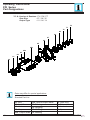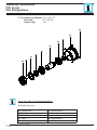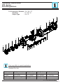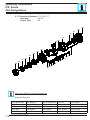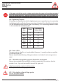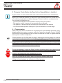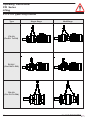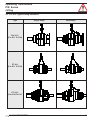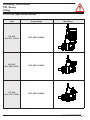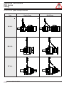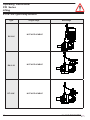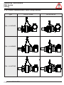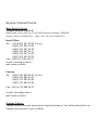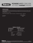
1
YILMAZ REDÜKTÖR ISO 9001
YILMAZ REDÜKTÖR ISO 9001
P/R Series Gear Units
OIPCE 0101-1112
Operating Instructions
Operating Instructions
P/R Series
Contents
Contents..................................................................................................................03
1 -How To Use This Manual..................................................................................... 04
2 -Unit Designation...................................................................................................05
2.1- Detailed unit designation ............................................................................. 05
2.2- Nameplate, unit designation......................................................................... 06
3. Standard type Gearbox Part List...................................................................... 07
3.1- P/R Output Group....................................................................................... 07
3.2- Gear Group
3.3 Input Side..................................................................................................... 16
4- Safety ................................................................................................................. 20
4.1- Intended Use................................................................................................ 21
4.2- Improper Use...............................................................................................21
4.3- Safety Instructions........................................................................................ 22
4.3.1- General Safety Instructions................................................................. 21
4.3.1.1- Working on the gear reducer.................................................... 21
4.3.1.2- Operation................................................................................ 21
4.4- Tightening Torques....................................................................................... 22
4.5- Case of Fire..................................................................................................22
5 -Things to Check Before the Gear Unit or Geared Motor is Installed............. 23
5.1- Transportation and Lifting............................................................................. 23
5.1.1 P...01L Types Lifting Positions.............................................................. 24
5.1.2 P...01K Types Lifting Positions............................................................. 26
5.1.3 R...01K Types Lifting Positions............................................................. 28
5.1.4 P Series Combined with E Series Lifting Positions.............................. 29
5.1.5 R Series Combined with E Series Lifting Positions.............................. 30
5.2- Storage....................................................................................................... 31
6- Installing The Gear Unit.................................................................................... 31
6.1- Before you start............................................................................................ 31
6.2- Check the shaft dimensions to fit ................................................................ 32
6.3- Check the ambient temperature................................................................... 32
6.4- Check the voltage supply............................................................................. 32
6.5- Check the mounting position........................................................................ 35
6.6- Use of breather plug..................................................................................... 35
6.7- Check the oil level........................................................................................ 35
6.8- Check shaft ends and mounting faces......................................................... 35
6.9- Cover abrasive ambient............................................................................... 35
6.10- Check accessibility to filling, breather and drain plugs............................. 36
2
YILMAZ REDÜKTÖR
Operating Instructions
P/R Series
Contents
7- Mechanical Installation ..................................................................................... 36
7.1- Assembling customer shaft with shrink disc................................................37
7.2- Disassembling customer shaft with shrink disc...........................................38
7.3- Assembling gear unit with torque arm..........................................................40
7.4- Fitting output shaft elements....................................................................... 42
7.5- Correct position of output shaft elements..................................................... 42
7.6- Correct position of Splined Shaft output assembling................................... 42
7.7- Fitting couplings........................................................................................... 43
8- Maintenance and Inspections .......................................................................... 44
9- Lubrication .........................................................................................................45
9-1- Oil Types......................................................................................................45
9.2- Changing the oil........................................................................................... 46
9.3- Mounting Positions....................................................................................... 46
9.4- Oil Quantities. (lt) ....................................................................................... 51
9.5- Oil plugs.......................................................................................................55
9.6- Oil Expansion Tank...................................................................................... 59
10- Hydraulic Motor................................................................................................ 60
11- Troubleshooting Guide.................................................................................... 62
12- Disposal............................................................................................................67
11.1- Disposal of Oil.......................................................................................... ..67
11.2- Disposal of Sealing.....................................................................................67
11.3- Disposal of Metal........................................................................................67
13- Appendix..........................................................................................................68
Warranty Conditions.........................................................................................69
Warranty Declarations......................................................................................70
YILMAZ REDÜKTÖR
03
Operating Instructions
P/R Series
General Informations
1 -How To Use This Manual
Take attention to the following safety and warning signs for proper understanding and quick reference.
Electric Hazard; Can cause severe or fatal injuries.
Mechanical Hazard; Can cause severe or fatal injuries.
Likely to be Hazardous; Can cause minor or fatal injuries
Damage Risk; Can damage the drive or environment
Important Information
EC Machinery Directive:
Within terms of the EC machinery directive 2006/42/EC , the gear reducer is not considered an autonomous machine, but as a component to install in machines.
Operation is prohibited within the area of validity of the 2006/42/EC directive, until it has
been determined that the machine, in which this product is installed, corresponds to the
regulations within this directive.
The operating instructions contain important information to ensure;
- Trouble-free operation
- Fulfilment of any rights to claim under guarantee
The operating instruction must be kept close to the gearbox and must be available in
case it is needed.
This operating instruction is written for P/R Series gear units and is applicable only for
P/R Series. If any different type of gearbox is used please ask YILMAZ REDUKTOR for
the operating instructions of that type.
This instruction can be used only for standard type geared units of YILMAZ REDUKTOR. For special application and modified gear units ask YILMAZ REDUKTOR for
validity.
This manual does not cover 94/9/EC compatible gearboxes. For 94/9/EC contact
YILMAZ REDUKTOR.
04
YILMAZ REDÜKTÖR
Operating Instructions
P/R Series
Unit Designation
2- Unit Designation
2-1 Detailed Unit Designation
Detailed P Series gear units designation for ordering (This Designation is different from the short
nameplate designation)
P N 11 0 2 L . 01 - Additional Information
8
1
2
3
4
5
6
7
Additional Information: (For PN, PV, RN, RV)
- If the gearbox unit is PN, RN Type:
Output Shaft Properties:
01 :Solid Output Shaft
0K :Splined Hollow Shaft DIN 5480
0L :Splined Hollow Shaft DIN 5482
0S :Shrink Disc
1K :Splined Solid Shaft DIN 5480
1L :Splined Solid Shaft DIN 5482
Optional for P24:
10 :Solid Output Shaft
K0 :Splined Hollow Shaft DIN 5480
L0 :Splined Hollow Shaft DIN 5482
S0 :Shrink Disc
K1 :Splined Solid Shaft DIN 5480
L1 :Splined Solid Shaft DIN 5482
Shaft Condition:
L: Input and Output Shafts on Same Axis
K: Input and Output Shafts Perpendicular
Number of Stage:
1
: Single Stage
2
: Two Stage
3
: Three Stages
4
: Four Stages
Revision Number
Gearbox Sizes:
11,12, 15, 16, 19, 23, 24, 27, 29, 35
Version of Gearbox:
V
: With Electric or Hydraulic Motor
N
: Motor Connection Flange (IEC, C26, M46)
T : Solid Input Shaft
Serie of Gearbox:
P
: Planetary Gearbox with Flange Mounted.
R
: Planetary Gearbox with Foot Mounted.
A06
63 size IEC B5 motor connection flange
A07
71 size IEC B5 motor connection flange
A08
80 size IEC B5 motor connection flange
A09
90 size IEC B5 motor connection flange
A10
100 / 112 size IEC B5 motor connection flange
A13
132 size IEC B5 motor connection flange
A16
160 size IEC B5 motor connection flange
A18
180 size IEC B5 motor connection flange
A20
200 size IEC B5 motor connection flange
A22
225 size IEC B5 motor connection flange
A25
250 size IEC B5 motor connection flange
C26
Flange code C, Shaft code 26 (HE Hydraulic Motor)
M46
Flange code M, Shaft code 46 (HG Hydraulic Motor)
- If PN, RN type gearbox unit connected with hydraulic motor:
HE330
Geometric displacement
Hydraulic motor type (HG or HE)
- If the gearbox unit is PV, RV type:
90S/4
Number of pole
Frame length
Motor size (63...-250...)
- If PN, RN type gearbox unit coupled with a worm gearbox:
EV063-71/4b
Iron core length
Number of pole
Motor size (63...-132...)
Size of worm gearbox (63-125)
Worm gearbox type
EV: With motor
EN: With motor flange
ET: Without motor
Examples
PT1202K.01
Without motor, solid output shaft, gearbox size 12, 2 stages, perpendicular
input and output shaft with flange
PV1902L.01-160M/6
Motor with 11 kW 900 rpm, solid output shaft, gearbox size 19, 2 stages,
parallel input and output shaft with flange
RV1502L.00-90S/6
Motor with 0,75 kW 900 rpm, hollow output shaft, gearbox size 15, 2 stages,
parallel input and output shaft, with foot
PN1102L.01-EV063-71/4b
Motor with 0,37 kW 1400 rpm, connected with worm gearbox size 63, solid
output shaft, 2 stages, parallel input output shaft, planetary gearbox size
11 with flange
YILMAZ REDÜKTÖR
05
Operating Instructions
P/R Series
Type Designation
2.2- Nameplate, unit designation
Nameplate unit designation is a short abbreviation from the detailed designation
A sample name plate for P/R Series
YILMAZ REDÜKTÖR
www.yr.com.tr
Made in Turkey
Type
: PV1902L.01.132M/4
Serial N. :100109820
Oil
Power:
7,5
kw
Ratio
: 56,25
Speed:
16
rpm
M.Positon : M1
: ISO VG 320 (Synthetic Oil) Oil Quantity: 2.0 lt
Abbreviations:
Serial N. : Serial Number
M.Position. : Mounting Position
Type Designation;
PV1902 L.01.132M/4
Type
Motor Type
Output Shaft Properties:
01 :Solid Output Shaft
0K :Splined Hollow Shaft DIN 5480
0L :Splined Hollow Shaft DIN 5482
0S :Shrink Disc
1K :Splined Solid Shaft DIN 5480
1L :Splined Solid Shaft DIN 5482
Optional for P24:
10 :Solid Output Shaft
K0 :Splined Hollow Shaft DIN 5480
L0 :Splined Hollow Shaft DIN 5482
S0 :Shrink Disc
K1 :Splined Solid Shaft DIN 5480
L1 :Splined Solid Shaft DIN 5482
Shaft Arrangement
L : Input and Output shafts are on same axis
K : Input and Output shafts are perpendicular each other.
06
YILMAZ REDÜKTÖR
Operating Instructions
P/R Series
Part Designations
3. Standard Type Gearbox Part List
3.1- Output Group
3.1-1 Version of Gearbox : RV / RN / RT
Gearbox Size
Output Type
:11 / 12 / 15 / 16 / 19 / 23 / 24 / 27 / 29 / 35
:01 / 1K / 1L
11
12
13
14
10
9
7
6
5a
4
2
1
8
5b
3
Parts may differ for special applications.
Standard Part List
1- Bolt
2- Seal Cover
3- Seal
4- Key
5a- Output Shaft
YILMAZ REDÜKTÖR
5b- Splined Output shaft
6- Bearing
7- Oil Plug
8- Footed output
9- Lifting Bolts
10- Bearing
11- Nilos Ring
12- Tab washer
13- Locknuts
14- Spacer
07
Operating Instructions
P/R Series
Part Designations
3.1.2- Version of Gearbox : PV / PN / PT
Gear Size
Output Type
:11 / 12 / 15 / 16 / 19 / 23 / 24
:01 / 1K / 1L
34
35
36
37
33
32
31
30
29b
27
28
29a
26
25
Parts may differ for special applications.
Standard Part List
25- Bolt
26- Seal Cover
27- Seal
28- Key
29a- Output Shaft
08
29b- Spline Output Shaft
30- Bearing
31- Output Flange
32- Oil Plug
33- Bearing
34- Nilos Ring
35- Tab washer
36- Locknuts
37- Spacer
YILMAZ REDÜKTÖR
Operating Instructions
P/R Series
Part Designations
3.1.3- Version of Gearbox : PV / PN / PT
Gear Size
Output Type
:11 / 12 / 15 / 16 / 19 / 23 / 24
:0S / 0K / 0L
53
54
52
51
50b
50a
49
48
47
46
45
49
48
47
46
Parts may differ for special applications.
Standard Part List
45- Shrink Disc
46- Bolt
47- Seal Cover
48- Seal
49- Bearing
YILMAZ REDÜKTÖR
50a- Hollow Shaft
50b- Spline Shaft
51- Bearing
52- Spacer
53- Output Flange
54- Oil Plug
09
Operating Instructions
P/R Series
Part Designations
3.1.4- Version of Gearbox : PV / PN / PT
Gear Size
Output Type
: 27 / 29 / 35
: 01 / 1K / 1L
69
70
71
72
68
67
66
65
64b
62
63
64a
61
60
Parts may differ for special applications.
Standard Part List
60- Bolt
61- Seal Cover
64b- Spline Output Shaft
65- Bearing
62- Seal
66- Housing
63- Key
67- Oil Plug
64a- Output shaft 68- Bearing
10
69- Nilos Ring
70- Tab washer
71- Locknuts
72- Spacer
YILMAZ REDÜKTÖR
Operating Instructions
P/R Series
Part Designations
3.1.5- Version of Gearbox : PV / PN / PT
Gear Size
Output Type
: 27 / 29 / 35
: S0
89
88
87
86
85
84
83
82
80
81
Parts may differ for special applications.
Standard Part List
80- Shrink Disc
81- Bolt
82- Seal Cover
83- Seal
84- Bearing
YILMAZ REDÜKTÖR
85- Hollow Shaft
86- Bearing
87- Spacer
88- Output shaft
89- Oil Plug
11
Operating Instructions
P/R Series
Part Designations
3.1.6- Version of Gearbox : PV / PN / PT
Gear Size
Output Type
: 27 / 29 / 35
: 0K / 0L
108
107
106
105
104
103
102
101
100
99
110
98
109
111
97
96
115
95
117
112
113
114
114
113
112
116
Parts may differ for special applications.
Standard Part List
95- Bolt
96- Seal Cover
97- Seal
98- Bearing
99- Bearing
12
100- Spacer
101- Output shaft
102- Carrier
103- Washer
104- Internal Gear
105- Sun Gear
106- Bearing
107- Flange
108- Bolt
109- Pin
110- Circlip
111- Pin
112- Washer
113- Bearing
114- Spacer
115- Planetary Gear
116- Circlip
117- Oil Plug
YILMAZ REDÜKTÖR
Operating Instructions
P/R Series
Part Designations
3.1.7- Version of Gearbox : PV / PN / PT
Gear Size
Output Type
:29 / 35
:0S
139
138
137
136
135
133
134
132
131
130
129
128
127
125
146
126
145
144
143
148
144
145
142
143
140
141
147
Parts may differ for special applications.
Standard Part List
125- Shrink Disc
126- Bolt
130- Bearing
131- Spacer
127- Seal Cover
128- Seal
129- Bearing
132- Output Flange 137- Bearing
133- Carrier
138- Flange
134- Washer
139- Bolt
YILMAZ REDÜKTÖR
135- Internal Gear
136- Sun Gear
140- Pin
141- Circlip
145- Spacer
146- Planetary Gear
142- Pin
143- Spacer
144- Bearing
147- Circlip
148- Oil Plug
13
Operating Instructions
P/R Series
Part Designations
3.2- Gear Group
3.2.1 Version of Gearbox : PV / PN / PT / RV / RN / RT
Gear Size
Output Type
:11/ 15
: ALL
160
161
159
158
157
156
155
164
163
162
165
Parts may differ for special applications.
Standard Part List
155- Washer
156- Carrier
157- Washer
158- Sun Gear
159- Internal Gear
14
160- Flange
161- Bolt
162- Pin
163- Needle Roller
164- Planetary Gear
165- Washer
YILMAZ REDÜKTÖR
Operating Instructions
P/R Series
Part Designations
3.2.2 Version of Gearbox : PV / PN / PT / RV / RN / RT
Gear Size
Output Type
:12 / 16 / 19 / 23 / 24 / 27 / 29 / 35
:ALL
174
175
173
172
170
171
176
178
181
180
177
179
Parts may differ for special applications.
Standard Part List
170- Carrier
171- Spacer
172- Sun Gear
173- Internal Gear
175- Bolt
176- Pin
177- Spacer
178- Planetary Gear
174- Flange
179- Spacer
YILMAZ REDÜKTÖR
180- Needle Roller
181- Washer
15
Operating Instructions
P/R Series
Part Designations
3.2.3 Version of Gearbox : PV / PN / PT / RV / RN / RT
Gear Size
Output Type
:11/ 12 / 15 / 16 / 19 / 23 / 24 / 29 / 35
:ALL
213
212
207
211
206
210
205
203
209
204
208
195
200
198
201
202
199
197
196
194
193
192
191
190
Parts may differ for special applications.
Standard Part List
190- Bolt
191- Seal Cover
192- Seal
193- Bearing
194- Bevel Gear
16
195- Key
196- Shaft
197- Spacer
198- Oil Plug
199- Flange
200- Bearing
201- Spacer
202- Cover
203- Bolt
204- Gear
205- Spacer
206- Nilos Ring
207- Bearing
208- Spacer
209- Bearing
210- Spacer
211- Circlip
212- Washer
213- Circlip
YILMAZ REDÜKTÖR
Operating Instructions
P/R Series
Part Designations
3.3 Input Side
3.3.1 Version of Gearbox : PV / PN / RV / RN
Gear Size
Input Type
:11/ 12 / 15 / 16 / 19 / 23 / 24 / 29 / 35
: IEC B5 Flange Type
227
225
223
226
224
222
221
220
Parts may differ for special applications.
Standard Part List
220- Circlip
221- Bearing
222- Input Shaft
223- Bearing
224- Seal
YILMAZ REDÜKTÖR
225- Input Flange
226- Oil Plug
227- Bolt
17
Operating Instructions
P/R Series
Part Designations
3.3.2 Version of Gearbox : PV / PN / RV / RN
Gear Size
Input Type
: 11/ 12 / 15 / 16 / 19 / 23 / 24 / 29 / 35
: C26 / M46 input type for Hydraulic motor
242
240
238
241
239
237
236
235
Parts may differ for special applications.
Standard Part List
235- Circlip
236- Bearing
237- Input Shaft
238- Bearing
239- Seal
18
240- Input Flange
241- Plug
242- Bolt
YILMAZ REDÜKTÖR
Operating Instructions
P/R Series
Part Designations
3.3.3 Version of Gearbox : PV / PN / RV / RN
Gear Size
Input Type
:11 / 12 / 15 / 16 / 19 / 23 / 24 / 29 / 35
:Solid input shaft
258
257
256
254
252
255
253
251
250
Parts may differ for special applications.
Standard Part List
250- Circlip
251- Bearing
252- Input Shaft
253- Key
254- Bearing
YILMAZ REDÜKTÖR
255- Seal
256- Input Flange
257- Bolt
258- Oil Plug
19
Operating Instructions
P/R Series
Safety
4- Safety
4.1- Intended Use
The gear reducer is designed for use in industrial machines. Please refer to our catalogue
or our web page for the maximum permitted torques and speeds. The most important
maximum permitted values are indicated on the nameplate of the product. But the all data
can be found on our product catalogues. Using the product out of the product catalogue/
nameplate’s permitted ranges will cancel the warranty/manufacturer declaration and
YILMAZ REDUKTOR will not take any responsibility.
The gear units are intended for industrial machines and may only be used in accordance
with the information provided in this manual the product catalogue and the nameplate
of the gearbox. They comply with the applicable standards and regulations and meet the
requirements of the directive 2006/42/EC. The gearbox must be started up, maintained
and operated according this manual. The gearbox must be incorporated with 2006/42/EC
confirming parts/machines.
A motor connected to the gear unit is only allowed to be operated in the frequency entries
so that the data provided on nameplate/catalogue of the gear unit is not exceeded and is
accordance with the nameplate/catalogue. The speed range will be provided on the name
plate if YILMAZ REDUKTOR is informed that the gear unit will be used with frequency
inverter. If not informed the nameplate will have a single fixed speed and only this speed
is allowed.
The electric motor and frequency inverter must be in accordance with 2006/42/EC
If the gear units input is used with variable speed gear unit, this must be informed to YILMAZ
REDUKTOR before ordering and on the nameplate the allowed maximum and minimum
speeds (speed range) will be provided. If not mentioned by ordering the gear units speed
will be a fixed single input speed and only this speed is allowed.
If the gear unit will be driven by belt / coupling / chain drive etc. the gear unit is only allowed
to be used according the nameplate/catalogue entries. Different speed, higher motor power,
higher radial/axial loads etc. than nameplate/catalogue is not allowed.
The ambient temperature must be between +5 , +40 celsius and no abrasive media must
attack the paint and seals. If different working conditions this must be informed to YILMAZ
before ordering.
The gearbox maintenance (oil change / check ) must be done according this manual
4.2- Improper Use
Every usage which exceeds the limits stated above, the nameplate and catalogue of the
product (especially highest torques and speeds) is not compliant with the regulations, and
thus prohibited.
The operation of the gear reducer is prohibited if;
-It was not mounted/installed according to regulations and this manual
-The gear reducer is very soiled
-It is operated without lubricant
-It is operated out of the permitted values provided on catalogues and/or nameplate.
20
YILMAZ REDÜKTÖR
Operating Instructions
P/R Series
Safety
4.3- Safety Instructions
4.3.1- General Safety Instructions
4.3.1.1- Working on the gear reducer
- Inappropriately executed work can lead to injury or damage.
Make sure that the gear reducer is only installed, maintained and dismantled by trained
technicians.
- Foreign bodies spinning through the air can cause grave injury.
Before putting the gear reducer into operation, check that there are no foreign bodies or
tools near the gear reducer
4.3.1.2- Operation
- Touching hot surfaces can lead to burns.
Do not touch the gear reducer if their operation temperatures are too high, or use suitable safety equipment like gloves.
-Rotating machinery can lead to injuries. There is danger of being trapped or pulled in!
Keep a sufficient distance and make safeguarding to rotating machinery. See relevant
norms EN349+A1, EN13857.
4.3.1.3- Maintenance
-An unintentional start of the machine during maintenance work can lead to serious accidents.
Make sure no one can start the machine while you are working on it.
- Even a brief running of the machine during maintenance work can lead to accidents if
the safety devices are not operating.
Make sure that all safety devices are mounted and active.
4.3.1.4- Lubricant
- Extended, intensive contact with oils can lead to skin irritations.
Avoid extended contact with oil, and clean oil off skin thoroughly.
- Hot oil can cause scalding.
When changing oil, protect yourself against contacting hot oil.
4.3.1.5- Ambient Conditions
- Standard gearboxes are allowed to work in ambient temperatures between +5 to +40
celsius unless differently specified on the nameplate.
Using the gear unit out of this range can cause damage to the gear unit or environment.
Over +40 celsius ambient conditions the gear unit surface temp could be so high causing
burns when touched.
YILMAZ REDÜKTÖR
21
Operating Instructions
P/R Series
Safety
-If the gear unit will be used in outdoor applications the gear unit must be prevented
from rain snow and dust. Entering substances inside the gear unit from seals can
damage the gear unit. Observe the safety instructions for outdoor use EN12100:2010.
4.4- Tightening Torques
All screwed connections for which a tightening torque is specified, must on principle
be tightened with a calibrated torque wrench and checked. Use the following torques
for the threaded bores over the gear unit housing. For connecting elements refer
to the mechanical installation part.
Bolt
Size
Class
Tightening
Torque [Nm]
M8
8.8
15
M10
8.8
20
M12
8.8
20
M16
8.8
40
M20
8.8
80
M24
8.8
200
4.5- Case of Fire
The gear reducer itself is not combustible. However, it usually contains a synthetic or mineral gear oil.
Please observe the following if the gear reducer is situated in a burning environment
4.5.1- Suitable extinguishing agents, Protective equipment
Always keep suitable extinguishing, protective equipment like carbon dioxide,
powder, foam, fog easily accessible around the gear unit.
-High temperature produce irritating steam.
Use a protective breathing apparatuses.
4.5.2- Unsuitable extinguishing agents
Do not spray with water!
22
YILMAZ REDÜKTÖR
Operating Instructions
P/R Series
Checking
5 -Things to Check Before the Gear Unit or Geared Motor is Installed
If gear motors are used, please also refer to the manual of the motor manufacturer.
Before you install the gearbox you have to be sure that the gearbox is arrived with the
all necessary equipment and without damage. Thinks to take into consideration before you start to install the unit;
- You have received the correct operation manual of the your product.
- The gearbox and all its parts are transported without damage.
- The gearbox is stored correctly according the instructions in this manual
- You have the latest product catalogue or you have access to our web page.
5.1- Transportation
When the goods arrive, first check for any damage. If some damage observed, immediately contact the transport company and inform about the damage. Contact YILMAZ
REDUKTOR for the damage and do not start to install the unit until it is agreed that the
damage has no effect of operation.
Please use the rope for lifting and carrying by wrapping around the gearbox or use the
eyebolt indicated position as shown on next pages. If you can not find lifting adequate
pictures for your product please contact YILMAZ REDUKTOR. The eyebolts should be
capable to carry the weight of gearboxes. Do not hang additional loads on the gearbox
by lifting. Use suitable hoisting equipment which is capable to hold the gear units weight.
Refer to the catalogue for various types weights.
Do not stay beneath / under the lifting / hoisting equipment which may cause serious
injuries by falling down objects, accidental movements, unexpected accidents.
Falling or hard placement can damage the gear unit.
Only use hoisting and securing equipment which is permitted for the size / weight of your
gear unit. Ensure that the load is slowly and carefully handled and placed.
Lifting and carrying types are indicated on following pages.
YILMAZ REDÜKTÖR
23
Operating Instructions
P/R Series
Lifting
5.1.1 P...01L Types Lifting Positions
Type
Single Stage
MultiStage
PV..01L
(For P11 To P24)
PV..01L*
(For P24 To P35)
PN..01L
(For P11 To P24)
24
YILMAZ REDÜKTÖR
Operating Instructions
P/R Series
Lifting
5.1.1 P...01L Types Lifting Positions
Type
Single Stage
MultiStage
PN..01L*
(For P11 To P24)
PT..01L
(For P11 To P24)
PT..01L*
(For P24 To P35
YILMAZ REDÜKTÖR
25
Operating Instructions
P/R Series
Lifting
5.1.2 P...01K Types Lifting Positions
Type
Single Stage
PV..01K
(For P11 To P24
NOT APPLICABLE
PN..01K*
(For P24 To P35)
NOT APPLICABLE
PT..01K
(For P11 To P24)
NOT APPLICABLE
26
MultiStage
YILMAZ REDÜKTÖR
Operating Instructions
P/R Series
Lifting
5.1.2 R...01L Types Lifting Positions
Type
Single Stage
MultiStage
RV..01L
RN..01L
RT..01L
YILMAZ REDÜKTÖR
27
Operating Instructions
P/R Series
Lifting
5.1.3 R...01K Types Lifting Positions
Type
RV..01K
28
Single Stage
MultiStage
NOT APPLICABLE
RN..01K
NOT APPLICABLE
RT..01K*
NOT APPLICABLE
YILMAZ REDÜKTÖR
Operating Instructions
P/R Series
Lifting
5.1.4 P Series Combined with E Series Lifting Positions
Type
For P11 To P24
For P27 to P35
PN....L.01+EV125
PN....L.01+EN125
PN....L.01+ET125
YILMAZ REDÜKTÖR
29
Operating Instructions
P/R Series
Lifting
5.1.5 R Series Combined with E Series Lifting Positions
Type
RN....L.01+EV125
For P11 To P24
For P27 to P35
NOT APPLICABLE
RN....L.01+EN125
NOT APPLICABLE
RN....L.01+ET125
NOT APPLICABLE
30
YILMAZ REDÜKTÖR
Operating Instructions
P/R Series
Checking
5.2- Storage
If the geared unit or geared motor will be stored up to 3 years refer to the following instructions;
With Packing;
-Use corrosion protection oil for the output shaft and connection surfaces like flange surface
or foot assembling surface. Seal the unit in a plastic wrap and pack it in container. A moisture
indicator should be placed around the container to observe the moisture. Relative atmospheric
humidity should not exceed 50%. The container should be kept under roof which protects
from snow and rain. Under this condition the gear unit can be stored up to 3 year with regular
check. The ambient temperature should be between -5 to 60 Celsius degrees
Without Packing;
-Use protection oil for the output shaft and connection surfaces like flange surface or foot
assembling surface. If no packing is used and the gearbox is stored without packing, the
ambient temperature should be between 5 to 60 Celsius degrees. The gearbox must be kept
under enclosed roof with constant temperature and constant humidity not exceeding 50%.
The storage should be free of dust and dirt and ventilated with filter. If the gearbox is stored
without packing it is recommended not to store more than 2 years and regular check during
this time is recommended.
If stored in open protect against insect damage.
6- Installing The Gear Unit
6.1- Before you start;
- Observe the gear unit for damages of storage or transportation. If any damage please
contact YILMAZ REDUKTOR.
- Be sure that you have all the equipment necessary for installing like; Spanners, torque
wrench, shims and distance rings, fixing devices for input and output elements, lubricant,
bolt adhesive etc.
- This manual is not for 94/9/EC (ATEX) conforming gear units. For 94/9/EC conforming
gear units refer to the ATEX range manual. ATEX conforming gear units have name plates
indicating the zone and the temperature class and are different from standard type geared
units. Therefore Standard units can not be installed on Potentially explosive atmospheres.
YILMAZ REDÜKTÖR
31
Operating Instructions
P/R Series
Checking
6.2- Check the shaft dimensions to fit
Type
Hollow Shaft
Diameter with
Shrink Disc
P11..
42
P12..
52
P15..
75
P16..
75
P19..
90
P23..
100
P24..
100
P27..
130
P29..
135
P35..
140
Customer
Shaft
Tolerance (H7)
Tolerance (h6)
Diameter with
Shrink Disc
+0.03
0
+0.03
0
+0.03
0
+0.03
0
+0.04
0
+0.04
0
+0.04
0
+0.04
0
+0.04
0
+0.04
0
42
52
75
75
90
100
100
130
135
140
0
-0.02
0
-0.02
0
-0.02
0
-0.02
0
-0.02
0
-0.02
0
-0.03
0
-0.03
0
-0.03
0
-0.03
Solid Output
Shaft
Diameter
50
50
60
60
80
90
90
110
120
140
Output Shaft
Tolerance
+0.02
0
+0.02
0
+0.02
0
+0.02
0
+0.02
0
+0.04
0.01
+0.04
+0.01
+0.04
+0.01
+0.04
+0.01
+0.04
+0.02
6.3- Check the ambient temperature;
The ambient temperature must be between +5 celsius to +40 celsius for standart type gear
units. If different contact YILMAZ REDUKTOR for special solutions.
6.4- Check the voltage supply;
The standard geared motors are supplied with 230/400 V 50/60 Hz. up to 3kW including
3kW and 400/690 V 50/60 Hz. over 3 kW and is indicated on the motors name plate unless
it is differently ordered. In case of only gear unit is supplied from YILMAZ please observe
the name plate of the electric motor and the instructions of the supplier. Check the basic
electric connection diagrams below. Use experienced electric technician.
Using wrong connection or voltage can damage the electric motor or environment.
32
YILMAZ REDÜKTÖR
Operating Instructions
P/R Series
Checking
The following wiring diagram is for standard 230/400 V 50Hz AC electric motors. For
different voltages please contact YILMAZ REDUKTOR. For gear units supplied without motor, refer to the motor manufacturers user Manuel.
The electric connection must be done by experienced electric technician.
T