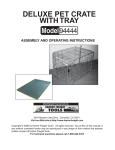
1
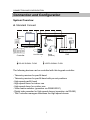
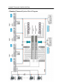
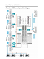
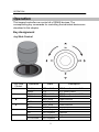
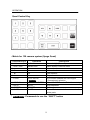
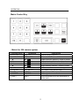
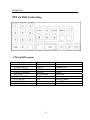
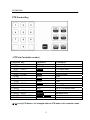
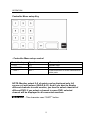
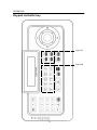
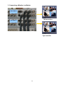
Mounting and Operating Instructions
For
RS485 Remote Control Unit
-1-
GENERAL INFORMATION
Dear Customer!
By selecting this product you have decided to use a professional
device which guarantees high quality and reliability. We’d like to thank
you very much for your confidence and kindly ask you to read the
following instructions carefully before commissioning in order to take
full advantage of all quality features regarding this product line.
Contents
General Information
Function Description ...……………………………………………………3
Scope of Delivery ……………………………………………………………3
Safety Precautions ………………………………………………………….…4
Connection and Configuration
System Overview ……………………………………………….……….…..5
Standard Connect ...……………………………………………………………5
Control via DVR Connect ……………………………………………………6
Standard Connect Camera System Block Diagram …………7
Control via DVR Connect Camera System Block Diagram ………………8
Connecting the Keyboard …..……………………………………….……9
Packing Detail ……………………………………………………………….10
Operation
Key Assignment ……………………………………………………………11
General Operation ………….…………….…………………………….....19
Control Command …………………….…….……………………………20
Function of Display …………………………….…………………………..23
How to connect the 256 camera system
Menu Setting ……………………………………………………………..…26
Connection of Video …………………………………………………………31
Exhibit
Troubleshooting ……………………………….……………………………33
Technical Specifications …………………………………………………..34
Some Words on Excess-Voltage …………………………………………35
Maintenance and Care …………………… ………………………………35
Technical Support ………………………………………………………….35
2
GENERAL INFORMATION
General Information
Function Description
This external keypad controller is used for the controlling, monitoring
and programming of RS485 system products.
This keypad controller comes in elegant extruded aluminum for low
profile table desk housing. Due to its compact size, it can be
integrated everywhere harmoniously. With this keypad controller, you
can control single components as well as complex CCTV systems.
Clients within the RS485 BUS are selected via the numeric keypad.
Contact with the corresponding client is confirmed by an acoustic
signal and additionally in the keypad’s info display. Messages such as
target address, type of receiver and e.g. camera movements are also
shown in the display.
If
you are using a matrix switcher, this is selected as central unit.
Connected pan/tilt heads or high speed dome cameras are
automatically enabled for control by the offset function integrated into
the matrix switcher. It is not necessary to additionally address them
directly.
This keypad controller comes with a robust joystick with integrated
zoom function (effected by turning the joystick). This makes it be
possible to control connected pan/tilt head camera stations
respectively high speed dome cameras reliably and easily. Just one
hand is required for tracking an object with the connected camera unit.
A potential separation with an optic-coupler (potential separator)
allows trouble-free data communication on the RS485 control line.
Scope of Delivery
▪ Remote control unit
▪ 3 m connection cable
▪ Power adapter 230/110 VAC to 12 VDC
▪ Connector box
▪ Operation manual
3
GENERAL INFORMATION
Safety Precautions
1.
Read these instructions carefully before connecting the
components in order to avoid malfunctions and damages caused
by improper installation or use.
2. Installation may only be carried out by authorized personnel
according to the local safety regulations.
3.
Only operate the device with the included power supply adapter
and the stated operating voltage.
4.
Never use the camera for other purposes except that designated.
5. Repairs and adjustments at the device may only be carried out by
authorized personnel.
6. Remove the device from power supply if you do not use it for an
extended period of time.
7. Immediately disconnect the device from power supply if any liquid
or solid matter should get into the housing and have it checked by
your authorized dealer before re-using.
8. Follow the warning notes attached to the device.
9.
Only use the device in dry, dust-free and non hazardous locations.
10. Only use the device indoors.
11. In order to avoid internal heat accumulation in the device:
- do not expose the device to direct sunlight.
- keep sufficient distance to direct heat sources.
4
CONNECTION AND CONFIGURATION
Connection and Configuration
System Overview
A. Standard Connect
Monitor
Junction
Box
Dome
(Indoor)
CCD
Matrix Switcher
Pan/Tilt Head
Dome
(Outdoor)
Controller
RS-485 SIGNAL FLOW
DVR
VIDEO SIGNAL FLOW
The following devices can be controlled with this keypad controller:
- Telemetry receiver for pan/tilt head
- Telemetry receiver for pan/tilt head with pre-set positions
- High speed pan/tilt head
- High speed dome for indoor use
- High speed dome for outdoor use
- Video matrix switcher (operation via RS485/232C)
- Digital video recorder for High speed domes (operation via RS485)
- The Controller manages directness the High speed domes
5
CONNECTION AND CONFIGURATION
B. Control via DVR Connect
Monitor
Junction
Box
CCD
Dome
(Indoor)
Matrix Switcher
Controller
RS-485 SIGNAL FLOW
Dome
(Outdoor)
DVR
VIDEO SIGNAL FLOW
The following devices can be controlled with this keypad controller:
- Telemetry receiver for pan/tilt head
- Telemetry receiver for pan/tilt head with pre-set positions
- High speed pan/tilt head
- High speed dome for indoor use
- High speed dome for outdoor use
- Video matrix switcher (operation via RS485/232C)
- Digital video recorder for High speed domes (operation via
RS485/232C)
- The Controller uses DVR and indirectness it manages the High speed
domes
6
CONNECTION AND CONFIGURATION
- Standard Connect System Block Diagram
7
CONNECTION AND CONFIGURATION
- Control via DVR Connect System Block Diagram
8
CONNECTION AND CONFIGURATION
Connecting the Keyboard
The clients are connected in a parallel way to the RS485 line
(conductors A and B). Up to 32 clients with a max. connection length
of 6 m can be connected to the main line.
The RS485 line can have a length of up to 1200 m. A transmission line
with 120 Ohm has to be connected to the start and to the end of it in
order to avoid signal reflections. The terminating resistor for the RS485
can be connected to each client with a jumper.
9
CONNECTION AND CONFIGURATION
PACKING DETAIL
1. CONTROLLER
3. MANUAL
2. JUNCTION BOX
4. LAN CABLE
5. AC ADAPTOR
& POWER CORD
- Power Supply
Only operate the device with the power supply adapter (12 V/DC)
included in the scope of delivery. Connect the power supply adapter to
the keyboard’s junction plug into the connector box.
The correct power supply is signaled by the LCD display.
- RS485 Interface
Connect the RS485 interface with correct polarity (TRX+ and TRX-) to
the junction box.
- LAN cable (RJ45)
Connect the controller to the junction box.
Don’t connect the controller to hub and network equipment.
10
OPERATION
Operation
This keypad controller can control all of RS485 devices. The
corresponding key commands for controlling the individual devices are
described in this chapter.
Key Assignment
Joy Stick Control
Joy Stick
Control
①4
②3
③ ▲
④ ▼
⑤ ◀
⑥ ▶
Operation
(ZOOM-)
ZOOM(ZOOM+)
ZOOM+
▲
FAST
▼
SLOW
◀
DIR
▶
PLAY/PAUSE
State
PTZ via DVR
PTZ
PTZ via DVR
PTZ
Menu setup
DVR Playback
Menu setup
DVR Playback
Menu setup
DVR Playback
Menu setup
DVR Playback
11
Description
PTZ Zoom Control via DVR
PTZ Zoom Control
PTZ Zoom Control via DVR
PTZ Zoom Control
Upper direction
Lower direction
Left direction
Direction
Right direction
OPERATION
Quad Control Key
- Matrix for 128 camera system (2page Quad)
Controller keys
① 1~8
② SPOT/ ESC
③ ▲
④ ▼
⑤ ◀
⑥ ▶
⑦ LV/PB
⑧ STATUS
⑨ AUTO
⑩ FREEZE
⑪ SHIFT
Operation
Description
1~8
MENU/ ESC
▲
▼
◀
▶
VCR/ AR RST
/ GRP A/B
QUAD/ PIP/ ENTER
AUTO
FREEZE
SHIFT
Numeric digit (Channel)
Menu screen/ Previous menu
Upper direction
Lower direction
Left direction
Right direction
VCR mode/ Release the event signal
/ Group(page) selection
Quad mode/ PIP mode/ Enter the next step
Auto sequence
Still image
Press this button to do the commands of
white parts
* White parts: Commands to use the “SHIFT” button
12
OPERATION
Matrix Control Key
- Matrix for 256 camera system
Controller keys
① 0~9, +10
② SPOT/ ESC
③ ▲
④ ▼
⑤ ◀
⑥ ▶
⑦ LV/PB
⑧ STATUS
⑨ AUTO
⑩ FREEZE
⑪ SHIFT
Operation
Description
0~9, +10
MENU/ ESC
▲/ OUT2
▼/ OUT3
◀/ OUT4
▶/ OUT5
VCR/ AR RST
PIP/ ENTER
AUTO/ FREEZE/ +
SHIFT
Numeric digit (Channel)
Menu screen/ Previous menu
Upper direction/ Monitor 2 output of matrix
Lower direction/ Monitor 3 output of matrix
Left direction/ Monitor 4 output of matrix
Right direction/ Monitor 5 output of matrix
VCR mode/ Release the event signal
PIP mode/ Enter the next step
Auto sequence/ Decrease of value
Still image/ Increase of value
Press this button to do the commands of
white parts
13
OPERATION
PTZ via DVR Control Key
- PTZ via DVR control
Controller key
Operation
Command
① 0~9, +10
② (FOCUS-)/ AUTO
③ (FOCUS+)/ FREEZE
④ (PRESET)/ SEARCH
⑤ (AF)/ COPY
⑥ (HOME)/ STATUS
⑦ (PTZ)/ SETUP
⑧ (IRIS-)/ FOCUS⑨ (IRIS+)/ FOCUS+
0~9, +10
FOCUSFOCUS+
PRESET
AUTO FOCUS
HOME
PTZ
IRISIRIS+
Numeric digit
Forward focus
Backward focus
Preset
Auto focus
Move to Home
DVR PTZ Mode
Iris of PTZ camera open
Iris of PTZ camera close
14
OPERATION
PTZ Control Key
- PTZ via Controller control
Controller key
Operation
Command
① 0~9
② PRST
③ (SHIFT + PRST)
④ PTRN
⑤ (SHIFT + PTRN)
⑥ SCAN
⑦ (SHIFT + SCAN)
⑧ TOUR
⑨ (SHIFT + TOUR)
⑩ (IRIS-)
⑪ (IRIS+)
⑫ (SHIFT + IRIS-)
⑬ (SHIFT + IRIS+)
⑭ (SHIFT + (IRIS-) (IRIS+) )
⑮ ENTER
0~9
PRESET
SETUP
PATTERN
HOME
SCAN
FUNC
TOUR
GROUP
IRISIRIS+
FOCUSFOCUS+
FOCUS- FOCUS+
Numeric digit
Preset
PTZ menu setup
Pattern
Move to Home
Scan
Function
Tour
Group
Iris of PTZ camera open
Iris of PTZ camera close
Forward focus
Backward focus
Auto focus
②~⑨ is only PTZ button. It is changed with the PTZ mode of the controller mode.
15
OPERATION
Controller Menu setup Key
- Controller Menu setup control
Controller key
Operation
Command
① 0~9
② SPOT/ESC
③ SHIFT
0~9
ESC
SHIFT
Numeric digit
Exit menu
Press this button to do the commands of
white parts
NOTE: Monitor output 2~5 of matrix can be displayed only full
screen or 4 split screen (QUAD A~D). And if you want to display
different channels in each monitor, you have to select channels of
different DVR. If you select a channel in same DVR, selected
channel will be displayed in all connected monitors.
* White parts - This character uses “SHIFT” button.
16
OPERATION
- Keypad controller
Control keys
① MODE SEL
② ID
③ MON
④ 1~9
⑤ 0/ AUDIO SEL
⑥ +10
⑦ CAM/ MULTI
⑧ AUTO/ / (F-)/ RELAY4 OFF
⑨ FREEZE/ +
/ (F+)/ RELAY4 ON
⑩ MENU/ ▲
⑪ PIP/ ▼
⑫ AR RST/ ◀
⑬ D-ZOOM/ ▶
⑭ SEARCH/(PRESET)
⑮ COPY/ (AF)
16 REC
○
17 LV/PB
○
18 SPOT/ ESC
○
19 STATUS/ ENTER
○
20 (PTZ)/ SETUP
○
21 SHIFT
○
22 PRESET/ SETUP
○
23 PATTERN/ HOME
○
24 SCAN/ FUNC
○
25 TOUR/ GROUP
○
26 (IRIS-)/ FOCUS○
27 (IRIS+)/ FOCUS+
○
28 FAST
○
29 SLOW
○
30 PLAY DIR
○
31 PB/ PAUSE
○
32 ZOOM○
33 ZOOM+
○
Description
Mode selection
ID selection
Monitor selection
Numeric digit (Channel/ ID selection and password
input)
Numeric digit (Channel/ ID selection and password
input)/ Audio selection
Numeric digit
Camera selection/ Multi-screen selection
Auto sequence mode/ Decrease of value
/ Focus control in DVR-PTZ mode/ Close the relay 4 in
“USER” mode
Still image/ Increase of value
/ Focus control in DVR-PTZ mode/ Open the relay 4 in
“USER” mode
Menu screen/ Upper direction
PIP mode/ Lower direction
Release the event signal/ Left direction
Digital zoom control/ Right direction
Search menu/ Preset in DVR-PTZ mode
Copy menu/ Auto Focus in DVR-PTZ mode
Recording/ Stop recording
Real view mode/ Playback mode
Spot mode/ Previous menu
DVR status display/ Enter the next step
DVR-PTZ mode/ Controller menu
Press this button to do the commands of white parts
Preset in CTRL-PTZ mode/ CTRL-PTZ menu
Pattern in CTRL-PTZ mode/ Home in CTRL-PTZ mode
Scan in CTRL-PTZ mode/ Function in CTRL-PTZ mode
Tour in CTRL-PTZ mode/ Group in CTRL-PTZ mode
Iris close in CTRL-PTZ or DVR-PTZ mode/ Focus
Iris open in CTRL-PTZ or DVR-PTZ mode/ Focus
Playback speed up (Up)
Playback speed down (Down)
Change of playback direction (Left)
Playback/ Pause (Right)
Zoom control in DVR-PTZ or CTRL-PTZ mode
Zoom control in DVR-PTZ or CTRL-PTZ mode
17
OPERATION
Keypad controller key
Only PTZ
Only DVR
18
OPERATION
General Operation
Camera selection:
Press the “CAM” button and you can see the cursor next to “SELECT
CAMERA” in LCD window. And press the desired camera number
button and then press the “CAM” button again.
NOTE: - Press the “ESC” button to revise the input value.
- You can use 1~3 digit. The controller will make a “beep”
sound and the input value will be erased if you input 4 digits.
Spot camera selection
Press the “CAM” button and then the “SPOT” button to select the spot
channel.
And press the desired camera number button and then the “CAM”
button again.
NOTE: - Press the “ESC” button to revise the input value.
- You can use 1~3 digit. The controller will make a “beep”
sound and the input value will be erased if you input 4 digits.
- If selected camera is PTZ camera, enter the PTZ mode
automatically.
(In case of setting PTZ camera in DVR)
ID selection:
Press the “ID” button and then select the desired number button.
ID means system ID of DVR or Quad/Matrix. (from 01 to 99)
- ID 01~16: DVR 1~16
- ID 17~19: Main monitor 1~3 of Quad/Matrix
- ID 20~22: Spot monitor 1~3 of Quad/Matrix
NOTE: Use 2 digits when inputting ID.
For example, if you want ID number “2”, you have to input “02”.
Controller menu
It changed the set of controller regulation to respect.
(Communication speed/ ID of connected devices)
Press the “SHIFT” button and then the “(PTZ) SETUP” button.
Select the desired value using the joy stick.
Press the “SPOT/ ESC” button to exit this menu. (Saving the revised
data automatically)
19
OPERATION
Control Command
- Keypad controller
Command
Controller menu
DVR or PTZ selection
ID selection
Display of single camera
Display of single spot camera
Output monitor selection
Output spot monitor selection
Controller key
SHIFT + (PTZ) SETUP
MODE SEL
ID + NUMBER(01~99)
CAM + NUMBER + CAM
CAM + SPOT + NUMBER + CAM
MON + NUMBER (2:V2 / 3:V3 / 4:V4 / 5:V5)
+ NUMBER(channel no.) + MON
MON + SPOT + NUMBER (2:V2 / 3:V3 / 4:V4 / 5:V5)
+ NUMBER(channel no.) + MON
- DVR control
Command
Spot channel selection
Live or Playback
Playback direction
Playback / Pause
Fast playback
Slow playback
DVR setup menu
Display digital zoom
Auto sequence
Still image
DVR system information
1~9CH selection
10~16CH selection
Display of multi-channel
Recording start & stop
Search menu
Copy menu
Controller key
SPOT + NUMBER
LV/PB
PLAY DIR(lower joy stick left)
PB/PAUSE(lower joy stick right)
FAST(lower joy stick up)
SLOW(lower joy stick down)
MENU
D-ZOOM
AUTO
FREEZE
STATUS
NUMBER
+10 + NUMBER
SHIFT + MULTI
REC
SEARCH
COPY
20
OPERATION
- PTZ via DVR control
Command
PTZ mode on/off
Iris of PTZ camera open
Iris of PTZ camera close
PTZ menu setup
Forward focus
Backward focus
Auto focus
Preset & Move
Speed up
Speed down
Forward zoom
Backward zoom
Controller key
(PTZ)
(IRIS-)
(IRIS+)
SHIFT + MENU
(FOCUS+)
(FOCUS-)
(AF)
(PRESET)
SHIFT + AUTO
SHIFT + FREEZE
Joy stick left turn
Joy stick right turn
- Key board control for High speed dome
Command
Preset
PTZ menu setup
Iris of PTZ camera open
Iris of PTZ camera close
Forward focus
Backward focus
Auto focus
Pattern
Home
Scan
Function
Tour
Group
Forward zoom
Backward zoom
Controller key
PRST
SETUP (SHIFT + PRST)
(IRIS-)
(IRIS+)
FOCUS+ (SHIFT + IRIS+)
FOCUS- (SHIFT + IRIS-)
FOCUS- + FOCUS+ (SHIFT + (IRIS-)(IRIS+))
PTRN
HOME (SHIFT + PTRN)
SCAN
FUNC (SHIFT + SCAN)
TOUR
GROUP (SHIFT + TOUR)
Joy stick left turn
Joy stick right turn
21
OPERATION
- Matrix control for 256 camera system
Command
ID selection
(256 Camera System)
Menu / Escape
Enter the next step
Move cursor
Change Value
VCR / Alarm reset
Auto sequence
Still image
Camera Selection of Output 1
Camera Selection of Output 2
Camera Selection of Output 3
Camera Selection of Output 4
Camera Selection of Output 5
Controller key
ID + NUMBER(01~16) (Main Monitor:17/ Spot
Monitor:20)
SPOT/ESC
ENTER
direction key(▲▼◀▶) / joy stick(▲▼◀▶)
AUTO/- , FREEZE/+
AR RST
AUTO/FREEZE/+
NUMBER
MON + 2 + NUMBER
MON + 3 + NUMBER
MON + 4 + NUMBER
MON + 5 + NUMBER
- Matrix control for 128 camera system (2page quad)
Command
ID selection
(128 Camera System)
Menu / Escape
Enter the next step
Move cursor
Change Value
VCR / Alarm reset
Group A/B selection
Quad / PIP screen
Auto sequence
Still image
Controller key
ID + NUMBER(01~08) (Main Monitor:17 / Spot
Monitor:20)
SPOT/ ESC
ENTER
direction key(▲▼◀▶) / joy stick(▲▼◀▶)
ENTER & direction key(◀▶)
AR RST
SHIFT + LV/PB
ENTER
AUTO
FREEZE
22
OPERATION
Function of Display
Number of camera
Selected address
Status information
Last command
The following data is displayed:
▪ selected camera number
The currently selected camera number is displayed.
(CAMERA: 001-128/256)
▪ selected address
The currently selected address of the target client gets displayed
(ID: 01 – 99)
- Matrix system for main output of DVRs (ID: 17)
- Matrix system for spot output of DVRs (ID: 20))
▪ last command
The last command gets displayed.
▪ Status information
“MODE SEL” button changes the currently the mode of the controller.
- DVR (DVR mode): The speed dome camera can be controlled by each
DVR via this controller.
- PTZ (PTZ mode): The speed dome camera can be controlled this
controller.
23
OPERATION
Operating of Display
After power input it is a first screen.
It is a condition which is set in initial DVR
mode.
Left DVR LED comes to light.
PTZ button can not use.
Press the MODE SEL button make DVR
mode change PTZ mode and left DVR
LED off.
MODE SEL button when during 2 seconds
it presses becomes the password input
hold status.
Default value is 0000 & enter button.
Presses the ID button and presses 2 place
numbers from in the number button and
the monitor image is changed with
correspondence DVR.
Becomes the DVR mode with automatic
movement and the CAMERA number
comes to erase.
Presses the CAM button and presses 3
place numbers from in the number button
and the monitor image is changed in
corresponding Channel.
Presses the MON button and 2~5 until it
presses 1 place number from in the
number button and the DVR selection
menu comes out and when 0~9 until it
presses 3 place numbers from in the
number button and the corresponding
monitor is changed with corresponding
camera image.
24
OPERATION
Menu setting of Display
SYSTEM SETUP
DVR SETUP
1. SPEED
1200 2400 4800
2. ID LINK MTXM
ID
17 18 19
CH
8
16
3. ID LINK MTXS
ID
20 21 22
CH
8
16
4. ID LINK DVR
ID
01 02 ~ 99
CH
4 8 9 16
5. ID LINK TEST
PTZ SETUP
1. SPEED
2. MODEL
9600
1200
2400
4800
9600
NONE
SPD
VC-C4R
SD-290
PELCO-D
DSC-230
DMP23
LPT-A100L
BOSCH
TK-C655/C676
EZ
PCS-SERIES
000 001 ~ 256
001 001 ~ 999
3. CH
ID
4. INFORMATION
CH
000
SUM
000
CTRL SETUP
1. BUZZER
ON
2. PASSWORD
ON
MAKE PASSWORD
3. F/W UPGRADE
4. INITIALIZE
OFF
OFF
25
19200
38400
19200 38400
SRX-100B
SCC-643
CS-854
PELCO-P
SK-D106
How to connect the 256 CAMERA SYSTEM
A. General installation
Menu Setting
Setting MENUs among DVRs and PTZ Cameras
1. DVR MENU Setting
SYSTEM ID & OUTPUT MODE Setting of RS-485
The SYSTEM ID sets the DVR especially different. Set up ID (1-16)
The Baud the rate sets with 9600. (Default 115200)
2. MATRIX & QUAD MENU Setting
There is not a necessity which it will change
Default speed 9600
Default ID 17
3. External Keyboard MENU Setting
The PTZ set the model name and the speed and the ID of the camera.
The PTZ set the Channel number where the video cable of the camera is connected.
(Channel number same to CAM + number + CAM)
26
Connection of RS485
Connect RS485 of DVR and PTZ camera at JUNCTION BOX.
Not use RS232 of DVR.
The junction box and the controller connect with the RJ45 cable.
27
B. Control via DVR installation
Menu Setting
I. Setting MENUs among DVRs and PTZ Cameras
1. DVR MENU Setting
1) PTZ Camera Type, PTZ Camera ID & Speed Setting of RS-485
2) SYSTEM ID & OUTPUT MODE Setting of RS-485
Set up ID(1-16), MODEL and BAUD RATE of the connected PTZ camera PTZ
camera to connect and control a PTZ camera with DVR. And you have to set the
OUTPUT MODE to RS-485.
28
II. MENU Setting among DVRs, Matrix and External Keyboard
1. DVR MENU Setting
BAUD RATE Setting of RS-232
2. MATRIX or QUAD MENU Setting
There is not a necessity which it will change
Default speed 9600
Default ID 17
3. External Keyboard MENU Setting
There is not a necessity which it will change
If DVR Channel is 4, 8 and 9 must change channel of correspondence id.
Keyboard Controller BAUD RATE Set.
1) Press the SHIFT and ID/CONTROLLER MENU key.
2) Select the COMM SPEED as 9600 using joy stick of Keyboard.
3) Default Value of BAUD RATE is 9600.
29
Connection of RS485
Connection of Control Signal
1. Connecting the PTZ Camera with DVR:
Connect the RS422/485 cable of PTZ camera with the terminal block of DVR.
2. Connecting a DVR or a Matrix to a External keypad controller:
Matrix
DVR
TX
TX+
TX
TX-
1. RS-232C Connection
(The SERIAL port of DVR or Matrix can connect RS-232C.)
2. RS-485 Connection
Connect the 485CONVERTER (RS-485 to RS-232C converter) to SERIAL port of DVR
to connect with DVR.
3. Connect the + line of RS-485 to the TRX+ of 485CONVERTER
and the – line of RS-485 to the TRX- of 485CONVERTER.
30
Connection of Video
1. Connecting the PTZ Camera with DVR:
Connect the VIDEO OUTPUT of PTZ Camera to CAMERA IN of DVR.
2. Connecting the DVR with Matrix:
Main IN
Spot IN
Spot OUT
Main OUT
Connect the BNC connecter of MONITOR OUTPUT to CAMERA IN of the Matrix for
the Monitor and the BNC connecter of SPOT OUTPUT to CAMERA IN of the Matrix
for the SPOT Monitor.
31
3. Connecting a Monitor to a Matrix:
Main Matrix
Main monitor
Spot Matrix
Spot monitor
32
EXHIBIT
Exhibit
Trouble shooting
Please contact your authorized dealer with an exact failure description if
none of the below mentioned remedy measures fixes your problem.
Error Description
Cause
No function
- Not plugged in
- Connects plug of the keyboard
controller not connected
- Incorrectly switched 120 Ohm
termination resistor
- Incorrectly assigned device
address of the client
- Fault in the client’s power supply
- Missing or incorrect cable
- Incorrectly switched 120 Ohm
termination resistor
- If twisted pair line is not shielded,
interference may occur
- Moving loads are plugged
incorrectly
- Power supply of one (several)
clients is defective
No communication
via RS485 interface
System crash
33
EXHIBIT
Technical Specifications
Application
RS485 transmitter for selection and control of a
maximum of 100 RS485 clients with an unlimited
number of control commands
Joystick
Yes (pan/tilt move and zoom wide/ tele control)
Display
16 characters x 2 line LCD
Optic coupler
For RS485
Housing Connection cord
Table desk housing
6 cores, 5m long, pre-assembled with Western plug
Operating voltage
12V DC
Consumption
3W
Addressing
Adjustable via jumper or software
Output
RS485 interface / BUSTRONIC protocol
Operating temperature
-10° C up to + 55° C
Air humidity
< 90 %
IP rating / class
IP40 / Class III
MTBF
80,000 hours
Dimensions (W x H x D)
342 x 165 x 96.8 mm
Housing color
ABS /
Accessories (included)
operating instructions, Western socket
Black
34
EXHIBIT
Some Words on Excess-Voltage
Excess-voltage is the most common reason for defects in electronic
equipment. That’s why the additional safety precautions for the
transmission devices mentioned in these instructions are so important.
These safety precautions avoid or at least minimize short-lived voltage
pulses (transients) on the data line.
Causes for excess-voltage:
direct strikes by flashes of lightning
indirect lightning strikes in distances of up to several kilometers
switching acts in the energy net
disturbances by house internal switching acts
The shielded line has to be conductive along the whole length of the
connection dis- tance and has to be grounded at least at both ends.
Only a shield on both sides can reduce double reaction. The
grounding of the shield has to be carried out with impedance as low as
possible.
This avoids spikes of several 1,000 V caused by bad shield connection.
If wires go from one building to another their wire shields must be able
to cope with high impulse currents for short periods of time.
This can only work if the shield cross section is large enough. This can
not be accom- plished by foil sheets alone.
Multiple-shielded cables can reduce – but not avoid – residual
interference on the signal leads.
Therefore, the use of additional charge eliminators is indispensable in
most cases.
We recommend information technology devices!
Maintenance and Care
Disconnect this controller from power supply before starting to clean it.
For reasons of electrical safety never clean the keyboard with water or
other liquid matters and never put the device underwater. Only use a
soft dry cloth for cleaning this controller.
A cleaning of this controller’s interior may only be carried out by
authorized personnel. Make sure to include these instructions when
handing the unit over to third parties.
Technical Support
Please contact the authorized dealer.
35