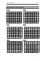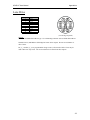
1
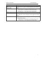
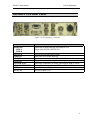
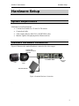
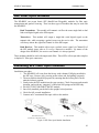
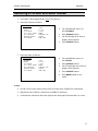
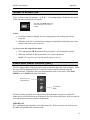
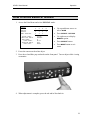
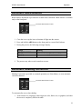
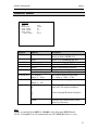
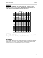
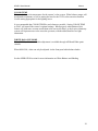
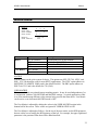
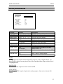
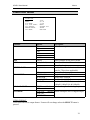
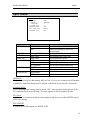
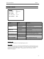
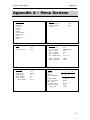
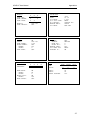
HD-RH1F TM OPERATION MANUAL ® HD-RH1F User Manual Table of Contents Table of Contents W`arnings/Safety Precautions................................................................................................... 3 Regulatory Compliance ............................................................................................................. 4 Product Description ................................................................................................................... 5 HD-RH1 Camera Head ..................................................................................... 5 HD-RH1F CCU Front Panel ............................................................................. 6 HD-RH1F CCU Rear Panel .............................................................................. 8 Hardware Setup ......................................................................................................................... 9 System Requirements...................................................................................... 9 Standard Hardware Connection ................................................................... 9 SFP Fiber Optic Modules ............................................................................... 10 Installing SFP Fiber Optic Modules ........................................................... 10 Remote Control ................................................................................................ 11 Standard Hardware Connection Tips ....................................................... 11 Operation .................................................................................................................................. 12 Video Formats & Rates .................................................................................. 12 Selecting a Format and Rate: Front Panel............................................. 14 Selecting a Format and Rate: Menus ...................................................... 15 Select a Scene File .......................................................................................... 16 Electronic Level Control (ELC) .................................................................... 16 White Balance ................................................................................................... 17 How to White Balance: Automatic (AWB) .............................................. 17 How to White Balance: Manual .................................................................. 18 Automatic Black Balance .............................................................................. 19 Automatic Shading Correction .................................................................... 19 Panel Lock .......................................................................................................... 20 Menus ........................................................................................................................................ 21 Navigating the Menus .................................................................................... 21 Selecting a Menu Option and Parameter................................................ 22 User Area On-Screen Entry ......................................................................... 23 Gain Menu .......................................................................................................... 24 Shutter Menu..................................................................................................... 25 Auto Shutter Area Presets ........................................................................... 27 Detail Menu ........................................................................................................ 28 Paint Menu.......................................................................................................... 29 AWB Area Presets ............................................................................................ 31 1 HD-RH1F User Manual Table of Contents Table of Contents Matrix Menu ....................................................................................................... 32 Gamma Menu .................................................................................................... 33 Level/Knee Menu ............................................................................................. 35 Video Out Menu ................................................................................................ 36 Sync Menu .......................................................................................................... 38 Feature Menu .................................................................................................... 39 Lens Menu .......................................................................................................... 40 Appendix A – Menu Screens ................................................................................................... 41 Appendix B: Connector Pin-Outs .......................................................................................... 43 Appendix C: Genlock Compatibility ..................................................................................... 45 Appendix D: 720p Doubled Rates .......................................................................................... 46 Appendix E: Specifications...................................................................................................... 47 List of Figures Figure 1. Camera head components ............................................................................................................... 5 Figure 2. CCU – front panel ........................................................................................................................... 6 Figure 3. CCU connectors – rear panel .......................................................................................................... 8 Figure 4. Standard Hardware Connection ...................................................................................................... 9 Figure 5. SFP Fiber Optic Module Installation ............................................................................................ 10 2 HD-RH1F User Manual Regulatory Warnings/Safety Precautions The following must be read and followed before using the HD-RH1. • Power supply: Nominal Voltage: 12V DC Absolute Minimum: 9V DC Absolute Maximum: 22V DC (peak) 3A maximum current requirement • Use only the specified power source voltage and connection cord. The wrong source could result in fire or electric shock. • Do not use the camera in situations that exceed the temperature specifications ( 0° to 40° C ). This may cause malfunction and/or damage the camera. • Do not touch the power cord or cables during a thunderstorm. • Operation near any appliance which generates strong magnetic fields may give rise to noise in the video signals. • Do not place unit into a confined space. Make sure adequate ventilation is available at all times during use. Failure to do so may cause your unit to overheat and cause a fire hazard or electric shock. • Electric shock warning: Do not remove top cover. There are no user serviceable parts inside. • Use with recommended accessories only. • Do not use the camera in a place where it could come in contact with water, moisture, steam, dust, or smoke. This could cause fire, electric shock, or camera failure. • To reduce the risks of fire, shock and damage, do not expose this unit to rain, snow, inclement weather, moisture, or high humidity. Keep this unit away from all liquids. Do not place liquid containers on the top of the unit. 3 HD-RH1F User Manual Regulatory Regulatory Compliance USA: WARNING: This equipment has been tested and found to comply with the limits for Class A digital device pursuant to Part 15 of the FCC Rules. These limits are designed to provide reasonable protection against harmful interference when the equipment is operated in a commercial environment. This equipment generates, uses, and can radiate radio frequency energy and, if not installed and used in accordance with the instruction's manual, may cause interference to radio communications. Operation of this equipment in a residential area is likely to cause interference in which case the user will be required to correct the interference at his own expense. The user is cautioned that changes and modifications made to the equipment without approval of the manufacturer could void the user's authority to operate this equipment. CANADA: This Class A digital apparatus meets all requirements of the Canadian InterferenceCausing Equipment Regulations. Cet appareil numerique de la classe A respecte toutes les exigences du Reglement sur le materiel brouilleur du Canada. DISPOSAL: This product contains some components with regulated disposal due to environmental considerations. This symbol means that used electrical and electronic products should not be mixed with general household waste. For disposal or recycling information please contact your local authorities, or the Electronics Industries Alliance. If you wish to discard this product, please contact your local authorities or dealer and ask for the correct method of disposal. 4 HD-RH1F User Manual Product Description Product Description The HD-RH1 is a professional 3CCD remote head camera system that offers the versatility of 720p, 1080i, 1080p, 480i (NTSC), and 576i (PAL) at all standard frame rates. HD-RH1 Camera Head Cable terminal Lens mount Front Side Figure 1. Camera head components Part Description Accepts C-mount style lens. Lens mount. Cable connection to CCU. Cable terminal Tripod mount (optional) 1/4-20 and 3/8-16 screw mounts. Rear HD-RH1F User Manual Product Description HD-RH1F CCU Front Panel Figure 2. CCU – front panel Button On/Off switch Format Rate File Panel Lock Bars Menu Arrow Keys Select Function Powers camera on and off. Press and hold to cycle through format options: · The format does not change until you release the button. · If you release on the current format setting, nothing changes. · See Operations and/or Video Output Menu for more detail on Format options. Press and hold to cycle through rate options: · Only rates for selected format are available. · The rate does not change until you release the button. · If you release on the current rate setting, nothing changes · See Operations and/or Video Output Menu for more detail on Rate options. Press and hold to cycle through scene files and select one. Press to disable the front panel buttons and knobs. Panel is locked if LED indicator is illuminated. Press and hold to un-lock the front panel. Toggles the display of the color bar test pattern. Press to access the on-screen Menu, or to exit out of a menu without making a selection. (See Using Menus ) Press to navigate to a menu, menu option, or parameter. · Up and down scrolls through vertical list of menu options. · Right / left displays parameters for a selected menu option. Press to select/enable a menu option. Note: A menu selection replaces a front panel setting and vice-versa. 6 HD-RH1F User Manual Button ELC (+Level LED) AWB ABB Gain/Level Knob Red knob/Blue knob Product Description Function Used to active ELC mode, or variable adjustment of the electronic shutter. Press and hold to perform an Automatic White Balance. · Mode must be set to AWB in the White Balance Menu. · See Operations – Video Output Setup for more detail. Press and hold to perform an Automatic Black Balance. When Manual Gain is enabled (via menu), use this knob to adjust gain. When ELC is active, this knob is used to adjust the electronic shutter Press pop-out buttons to manually adjust red and blue gain levels for Manual White Balance. · Mode must be set to MANUAL in the White Balance Menu. · See Operations – Video Output Setup for more detail. 7 HD-RH1F User Manual Product Description HD-RH1F CCU Rear Panel Figure 3. CCU connectors – rear panel Part Function SD/HD-SDI LINK A LINK B SDI LOCK FIBER I/O REMOTE DVI-I port Y/G, Pb/B, Pr/R ANALOG GENLOCK LENS DC 12V IN Single-link or Dual-Link HD-SDI (SMPTE-292) Single-Link SD-SDI (SMPTE-259) HD-SDI and SD-SDI genlock input Fiber optic SFP module interface Remote control interface: RS-232 or RS-485 Digital Video Interface – digital and analog outputs. Three BNC connectors for analog video output, RGB or YPbPr. Analog Genlock input, Tri-level (HD) or Bi-level (SD) sync Interface for motorized lens drive DC power input (12V) 8 HD-RH1F User Manual Hardware Setup Hardware Setup System Requirements Minimum System Requirements: • C-mount lens suitable for 1/3 inch 3-CCD camera. • Camera head cable. • Video output cable for SDI, DVI, or RGB/YPbPr video. • Monitor capable of displaying desired format and rate. Standard Hardware Connection Figure 4 illustrates the standard hardware connection for video output. Camera cable connects to front of controller CCU Rear Panel Lens Camera head DC power supply HD video monitor Figure 4. Standard Hardware Connection . 9 HD-RH1F User Manual Hardware Setup SFP Fiber Optic Modules The HD-RH1F can accept Iconix SFP (Small-Form Pluggable) modules for fiber optic transmission and genlock sourcing. There are three types of modules that may be used with the HD-RH1F: Dual Transmitter: This module will transmit via fiber the same single-link or dual link serial digital signal as the SDI outputs. Transceiver: This module will output a single-link serial digital signal on the transmit side, while accepting a genlock source on the receive side. The transmitter will always mirror the signal on Channel A of the SDI output. Dual Receiver: This module with accept a genlock source signal via Channel B of the SFP module (same side as if it were a transceiver module). By nature of the design of the HD-RH1F, the receiver on Channel A is always ignored. These modules should be used with single-mode fiber. These SFPs will accept either simplex or duplex LC fiber optic connectors. Installing SFP Fiber Optic Modules Installation procedure: 1. The HD-RH1F will come from the factory with a dummy EMI plug installed in the SFP cage. Remove it by pressing on the release tab, and pulling out gently. 2. The new modules should be prepared by ensuring that the locking bail is in the unlocked (down) position. 3. Gently insert the SFP module into the cage opening. Check for proper and smooth insertion, and avoid any “snagging” of the metal leaf springs on the SFP body. 4. DO NOT TWIST OR FORCE the SFP module. 5. Once fully installed, put the bail in the upright, locked position. 6. Check for full, secured installation. 7. Connect an LC-terminated fiber optic cable to the module. SFP Module Insertion (Bail shown in unlocked position) LC Cable Insertion Figure 5. SFP Fiber Optic Module Installation 10 HD-RH1F User Manual Hardware Setup Removal procedure: 1. Disconnect the LC fiber optic cable, if connected. 2. Unlatch the bail on the SFP module, and move the bail to its downward position. This will unlock the module from the cage. 3. Gently pull the module out from the cage. 4. Replace the dummy EMI plug when fiber optic modules are not in use. Remote Control This camera is compatible with the Iconix RCP-160 Remote Control Panel, and may be remotely controlled via RS-232 or RS-485 interface. Standard Hardware Connection Tips 1. Verify that the CCU power switch is in the OFF position. 2. Attach the lens to the camera head. 3. Connect the camera head to the head cable. Line up the red dots on the connector with the red dots on the camera and press in. 4. Connect the head cable into the CCU connector on the front panel. 5. Connect the video output monitor to the CCU via the appropriate cable. 6. Connect the DC power supply cord into the DC 12V connector on the controller back panel. 7. Turn on the video monitor. 8. Flip the controller power switch to the ON position. 9. Press the BARS button and verify that color bars are displayed. 11 HD-RH1F User Manual Operation Operation Video Formats & Rates The HD-RH1 is capable of generating images any of 31 format/frame rate combinations. The following chart lists the available combinations: 720p Frame Rates 60 59.94 50 30 30n60 29.97 29.97n59.94 25 25n50 24 24n60 23.98 23.98n59.94 29.97 25 24 23.98 1080i Rates 60 59.94 50 1080p Frame Rates 60 59.94 50 30 1080sF Frame Rates 30 29.97 25 24 23.98 480i Rate 59.94 576i Rate 50 12 HD-RH1 User Manual Operation 1080sF/1080PsF For purposes of brevity and clarity, the 1080sF nomenclature is used in this manual and in the HD-RH1 operation to stand for what is also known as 1080PsF (Progressive Segmented Frame). 1080p and Dual Link The Dual-Link signal for 1080p50, 1080p59.94, & 1080p60 is implemented per SMPTE372. Either link used independent of the other will appear as a single 1080i 4:2:2 signal. The Video Payload ID (SMPTE-352) embedded in the digital stream can be used to differentiate between 1080p and 1080i when in this mode. HD-SDI and SD-SDI The HD-RH1 automatically switches to SD-SDI (SMPTE-259) when in 480i and 576i. The only colorspace mode available for SD-SDI is SINGLE 4:2:2. Standard Definition Aspects 480i and 576i modes may also be set up for use in Anamorphic 16:9, Letterboxed 16:9, or cropped 4:3 aspects. Doubled 720p Frames To accommodate certain recording deck, the slower frame rates for 720p (23.98-30Hz) have the option to be “pulled-up” to either a double (2:1 ratio) frame rate, or a 3:2 style (actually a 2:5 frame-to-carrier ratio). The nomenclature used for this device in the HDRH1 is 720p24n60, which means 720p resolution with 24-frame native content on a 60Hz carrier. See Appendix D for more information on Doubled 720p frames. 13 HD-RH1 User Manual Operation Selecting a Format and Rate: Front Panel Press and Hold buttons to cycle through options 1. Press and hold the FORMAT key on the front panel to cycle through the format options. 2. When the desired Format LED is lit, release the button. The Format is not selected until the button is released. If the button is released on the format or rate that was already active, nothing changes. 3. Press and hold the RATE key on the front panel to cycle through the available rates. 4. When the desired Rate LED is lit, release the button. The Rate is not selected until the button is released. OPERATIONAL NOTES: • See the Video Output Menu section for a list of the rates available for each format. • Only those rates valid for a format are available for selection. • The 30 rate is only available from the Video Output menu. There is no LED indicator on the front panel. If no LED is illuminated for RATE, then 30/29.97 is assumed. • If F/P RATE mode is 1.001 in the Video Output menu, the whole number on the front panel represents the fractional rate. For example, when 1.001 is active, and 60 is selected on the front panel, 59.94Hz is the actual result. The factory default setting for F/P RATE is 1.001. To use the front panel to select a non-fractional rate, first set the F/P RATE to 1. (See Video Output Menu section.) • The 720p format in rates 23.98 through 30 has the option of being frame-doubled to a faster output rate. For example, 25-frame content can be output on a 50-frame signal. For quick operation from the front panel this mode is enabled or disabled by the F/P 720P CARR option in the Video Output menu. • A format/rate setting in the menu replaces the front panel setting and vice-versa. 14 HD-RH1 User Manual Operation Selecting a Format and Rate: Menus 1. Access the Video Output Menu. (See Using Menus.) 2. Select the Format as follows: VIDEO OUT >FORMAT: RATE: F/P RATE: F/P 720P CARR: SDI OUTPUT: ANALOG MODE: DVI MODE: 720P 59.94 1.001 NORM SINGLE 422 YPBPR RGB-VGA Use up and down arrows to select FORMAT Press SELECT button Use left & right arrow keys to display desired option. Press SELECT button. Use up and down arrows to select RATE. Press SELECT button. Use left and right arrow keys to display desired option. Press SELECT button. Press MENU button to exit menu. 3. Select the Rate as follows: VIDEO OUT FORMAT: >RATE: F/P RATE: F/P 720P CARR: SDI OUTPUT: ANALOG MODE: DVI MODE: 720P 59.94 1.001 NORM SINGLE 422 YPBPR RGB-VGA NOTES: • See the Video Output Menu section for a list of the rates available for each format. • Only those rates valid for a format are available for selection. • A format/rate selection in the menu replaces the front panel selection and vice-versa. 15 HD-RH1 User Manual Operation Select a Scene File There are three scene file locations – A, B, & C – for storing settings. Parameters are stored in the currently selected/active scene file. The front panel FILE button can switch among the scene files as needed. NOTES: • If a feature setting is changed, the new setting replaces the setting stored in the scene file. • When the scene file is switched, the settings are immediately loaded from the values stored in the newly active scene file. To select a scene file using the front panel 1. Press and hold the FILE button on the front panel to cycle through the options. 2. When the LED next to the desired letter is lit, release the button. NOTE: The scene file is not selected until the button is released. Electronic Level Control (ELC) The ELC button on the front panel can be used to manually adjust the Gain or Shutter. When the Level LED is illuminated the ELC exposure can be manually adjusted using the Level/Gain knob. When the LED is not illuminated the knob is only active if the Gain MODE is set to MANUAL in the Gain Menu. Electronic Level Control Button Level/Gain Knob Electronic shutter and gain can be adjusted by either the menu or by the use of the ELC button and Level/Gain knob on the front panel. See Gain Menu and Shutter Menu sections for more information on menu parameter adjustments. IMPORTANT ELC and Manual gain cannot be used at the same time. If the user turns one of the two on, the other will automatically be deactivated. 16 HD-RH1 User Manual Operation White Balance White Balance adjusts the camera for accurate color rendition. There are two modes, selected from the “PAINT” menu (see Using Menus and White Balance Menu.): • NORM (Automatic White Balance, AWB offset, White paint controls) • MANUAL (Front Panel White adjust only) Automatic White Balance button Red and Blue control knobs for Manual White Balance. How to White Balance: Automatic (AWB) 1. Focus the camera on any white object. 2. Press and hold the AWB button on the front panel until the AWB IN PROGRESS message appears. The camera automatically performs the white balance adjustment and stores the data in the active scene file. 3. During the process, the following messages display: Message AWB IN PROGRESS AWB OK AWB FAIL Meaning AWB is in progress AWB has completed successfully AWB failed to complete OPERATIONAL NOTES: • Select the appropriate COLOR TEMP in the PAINT menu before white balancing • The default preset area for AWB is A. The area preset may be changed via the PAINT menu. (See Using Menus and PAINT Menu.) • When the menu MODE is set to AWB, the Red and Blue knobs on the front panel are disabled 17 HD-RH1 User Manual Operation How to White Balance: Manual 1. Access the Paint Menu and select MANUAL mode. PAINT WHITE: BLACK: MAN SHADING: COLOR TEMP: >WHT BAL MODE: AWB AREA: -USER AREA: SHADING MODE: -AUTO SHD: R 0 0 _0 G 0 0 0 B 0 0 0 D5600 MANUAL A EDIT OFF EXEC M . 0 . Use up and down arrows to select MODE Press SELECT BUTTON. Use right arrow to display MANUAL option. Press SELECT button. Press MENU button to exit menu. 2. Focus the camera on the white object. 3. Press the red and blue pop-out knobs on the front panel. Turn to adjust while viewing on monitor. 4. When adjustment is complete, press the red and/or blue knob in. 18 HD-RH1 User Manual Operation Automatic Black Balance Black balance adjustment is provided for accurate black coloration. Black balance is available only on the front panel. Automatic Black Balance button 1. Close the iris or cap the lens to eliminate all light into the camera. 2. Press and hold the ABB button on the front panel to execute black balance. 3. During the process, the following messages display: Message ABB IN PROGRESS ABB OK ABB FAIL Meaning Calibration is in progress Calibration has completed successfully Camera cannot achieve black balance 4. The process may take several seconds to execute. Automatic Shading Correction Shading Correction is provided as a manual operation (see Paint Menu), or as an automatic correction function. Automatic Black Balance button To automatically correct lens shading: 1. Point camera at a completely white target (no color, black, text, or graphics) such that the screen is completely filled with white. 19 HD-RH1 User Manual Operation 2. Set SHD MODE to AUTO in the Paint menu. 3. Select “SHD AUTO: EXEC” in the Paint menu to activate. 4. During the process, the following messages display: Message SHD IN PROGRESS SHD OK SHD FAIL SHD FAIL INVALID TARGET Meaning Shading Correction is in progress Shading Correction has completed successfully Cannot achieve correction Target unsuitable for automatic correction 5. The process may take several seconds to execute. NOTE: Auto Shading Correction may only be accurate for the zoom or iris setting at which it was applied. For variable zoom and iris conditions, SHD MODE may be best set to OFF, or MAN for manual adjustment. Panel Lock To reduce the risk of accidental changes to the camera while in use, the Panel Lock feature may be used. To lock front panel menus and knobs, push the PANEL LOCK button, and the LED will be illuminated. While locked, the camera can be accessed and controlled via a remote connection. To unlock the camera, press and hold the PANEL LOCK button until the LED turns off (approx. one second). 20 HD-RH1 User Manual Menus Menus The menus provide access to the camera settings. Some settings may be changed using either the front panel or menu; others may be changed only through a menu. Changes to settings are automatically stored in the currently selected scene file. To maintain the current file contents, select a different scene file before any changes are made. Navigating the Menus Menus may be navigated using the front panel keys as shown below. Vertical arrows scroll up and down list of options Horizontal arrows scroll right and left through parameters Displays Main Menu list or backs out without making a selection Selects a menu option or a parameter 21 HD-RH1 User Manual Menus Selecting a Menu Option and Parameter To select an option and parameter on a menu, proceed as follows: 1. Press MENU on the front panel to display the Main Menu. 6. Use the up and down arrow keys to scroll to the desired sub-menu. The “>” symbol appears next to the selection. MAIN MENU GAIN SHUTTER DETAIL PAINT MATRIX GAMMA LEVEL/KNEE >VIDEO OUTPUT SYNC FEATURE LENS 7. Press SELECT on the front panel to display the selected sub-menu. 8. Use the up and down arrow keys to select an option on the sub-menu. 9. Press SELECT button to select the menu option. The setting will be highlighted. 10. Use the right and left arrow keys to display the parameters for the selection. The available parameters display one at a time to the right. Indicates selected option VIDEO OUT > FORMAT: RATE: F/P RATE: F/P 720P CARR: SDI OUTPUT: ANALOG MODE: DVI MODE: 720P 59.94 1.001 NORM SINGLE 422 YPBPR RGB-VGA Use right and left arrow keys to scroll through available parameters 11. When the desired setting is displayed, press the SELECT button again to activate. 12. Press MENU to return to the Main Menu. NOTE: Pressing the MENU button at any time exits a menu or sub-menu. 22 HD-RH1 User Manual Menus User Area On-Screen Entry 1. In either White Balance menu (for AWB), or Shutter menu (for AUTO shutter), scroll the cursor to USER AREA EDIT by using the arrow keys, and pressing SELECT. 2. A 7x7 grid is displayed on the screen with a blinking cursor in one of the boxes. Blinking cursor The user area contains 49 light measurement zones (7 x 7). Each zone can be set to ON or OFF. 0 1 2 3 4 5 6 7 8 9 10 11 12 13 14 15 16 17 18 19 20 21 22 23 24 25 26 27 28 29 30 31 32 33 34 35 36 37 38 39 40 41 42 43 44 45 46 47 48 13. To define the USER area, turn ON the zone (boxes) to be included in the area: • • • Use the arrow keys to move the cursor to a zone and press SELECT. If the zone is OFF, it will turn ON. If the zone is ON, it will turn OFF 14. Be sure to turn ON all zones within the area being defined. Note: For the user area to be active, USER must be active for the AWB AREA for White Balance, or AUTO AREA option for Shutter. A separate USER area exists for both White Balance and Shutter. 23 HD-RH1 User Manual Menus Gain Menu GAIN MODE: FIXED GAIN: Function MODE OFF 0DB Options OFF (default) FIXED VAR FIXED GAIN Range: 0DB~15DB Description Disables gain adjustment. Sets Gain level to 0dB. Enables ability to set the gain value using the FIXED GAIN function on the menu. Enables ability to use the manual Gain knob on the front panel to adjust the gain Sets the gain value at a fixed level when the Gain MODE is FIXED. MODE Used to select between the gain modes. When in VAR mode, the gain is set via the frontpanel knob. This knob is inactive in any other mode. NOTE: Turning VAR on will disable Shutter ELC, and vice versa. FIXED GAIN Used to select the amount of gain when in FIXED mode 24 HD-RH1 User Manual Menus Shutter Menu SHUTTER MODE: EXPOSURE: SYNC-SCAN: AUTO LEVEL: AUTO AREA: -USER AREA: Function MODE OFF OPEN 0% 50 A EDIT Options Off (default) Description Disables individual shutter adjustment. Shutter position is OPEN (0%). Fixed Shutter is set to FIXED EXP value ELC Shutter controlled via LEVEL knob SYNC-SCAN Shutter is set to SYNC-SCAN position AUTO Shutter is automatically adjusted Default: OPEN Shutter position is fully open. EXPOSURE (See Table 8 for options available per frame rate.) Sets variable shutter position from SYNC-SCAN 0% (default) Range: 0 ~ 100% 0% = Open to 100% = 1/500 Sets auto shutter average picture level AUTO LEVEL Default: 50 Range: 0 ~ 100 Selects a predefined picture area to be AUTO AREA A (default) B used for AUTO exposure feedback C D Presets A through F shown in Figure 8. E F USER Selects the user-defined area for auto shutter level detection. ELC Shutter is controlled from OPEN to 1/10,000 via the front panel LEVEL knob. NOTE: Turning ELC on will automatically turn off VAR GAIN, and vice versa. 25 HD-RH1 User Manual Menus EXPOSURE When MODE is FIXED, this value sets the exposure time. Values are in units of seconds (e.g. 1/100 = 1/100sec = 0.01sec). OPEN denotes full frame exposure. See Table 8 below for FIXED exposures available for each frame rate. Frame Rate 23.98 24 25 29.97 30 50 59.94 60 1/32 1/33 1/40 1/48 1/50 1/60 1/96 1/100 1/120 1/125 1/250 1/500 1/1000 1/2000 1/4000 1/10000 SYNC-SCAN When MODE is SYNC-SCAN, this value sets the shutter exposure time, from the full frame period to 1/125sec (50-60Hz) or 1/100 (23.98-30Hz) in 1% increments. AUTO LEVEL When MODE is AUTO, this value sets the average picture level target for the automatic shutter system. Set to desired average brightness. Note that the Auto Shutter system only uses shutter; it will not use gain increase the level of the picture. 26 HD-RH1 User Manual Menus Auto Shutter Area Presets Area A: Area B: 0 1 2 3 4 5 6 0 1 2 3 4 5 6 7 8 9 10 11 12 13 7 8 9 10 11 12 13 14 15 16 17 18 19 20 14 15 16 17 18 19 20 21 22 23 24 25 26 27 21 22 23 24 25 26 27 28 29 30 31 32 33 34 28 29 30 31 32 33 34 35 36 37 38 39 40 41 35 36 37 38 39 40 41 42 43 44 45 46 47 48 42 43 44 45 46 47 48 Area C: Area D: 0 1 2 3 4 5 6 0 1 2 3 4 5 6 7 8 9 10 11 12 13 7 8 9 10 11 12 13 14 15 16 17 18 19 20 14 15 16 17 18 19 20 21 22 23 24 25 26 27 21 22 23 24 25 26 27 28 29 30 31 32 33 34 28 29 30 31 32 33 34 35 36 37 38 39 40 41 35 36 37 38 39 40 41 42 43 44 45 46 47 48 42 43 44 45 46 47 48 Area F: Area E: 0 1 2 3 4 5 6 0 1 2 3 4 5 6 7 8 9 10 11 12 13 7 8 9 10 11 12 13 14 15 16 17 18 19 20 14 15 16 17 18 19 20 21 22 23 24 25 26 27 21 22 23 24 25 26 27 28 29 30 31 32 33 34 28 29 30 31 32 33 34 35 36 37 38 39 40 41 35 36 37 38 39 40 41 42 43 44 45 46 47 48 42 43 44 45 46 47 48 27 HD-RH1 User Manual Menus Detail Menu DETAIL FOCUS ASSIST: DETAIL MODE: -LEVEL: OFF ON 2 Function Options FOCUS ASSIST ON OFF (default) DETAIL MODE ON (default) OFF DETAIL LEVEL Range: 0 – 10 Description Enables Focus Assist mode. Normal operation. Enables Detail Enhancer. No added enhancement processing. Level of enhancement. FOCUS ASSIST Focus Assist displays a neutral grey background and adds only the detail information from the video image. This can be used to find the tightest focus, even when shooting in lowcontrast environments. DETAIL MODE Used to turn on or off the detail enhancer. This enhancer is used for sharpening high frequencies and edge contrast. DETAIL LEVEL Used to increase or decrease amount of detail enhancement. 28 HD-RH1 User Manual Menus Paint Menu PAINT WHITE: BLACK: MAN SHADING: COLOR TEMP: WHT BAL MODE: AWB AREA: -USER AREA: SHADING MODE: -AUTO SHD: R 0 0 _0 G 0 0 0 B 0 0 0 M . 0 . D5600 NORM A EDIT OFF EXEC Function WHITE BLACK MAN SHADING COLOR TEMP Options Range: -99 to +99 Range: -99 to +99 Range: -100 to +100 3200 D4300 D5600 D6500 FLAT WHT BAL MODE NORM (default) MANUAL AWB Area A (default) B C D E F USER SHADING MODE AUTO, MAN, OFF Description White Paint control Black Level control Manual shading calibration Color system presets Sets white balance ranges and optimizes matrix for color correction Normal white balance paint control Enables ability to manually adjust white balance using the red and blue gain knobs on the front panel. (See Operations .) Selects a predefined picture area to be used for AWB. Presets A-F are shown in Figure 8. Selects the user defined white balance area. You must define the area first. You can define only one user area at a time. Sets mode for White Shading correction 29 HD-RH1 User Manual Menus COLOR TEMP This sets the base color temperature for the camera’s color system. White balance ranges will be adjusted to optimum, as well as setting the base for the 3CCD color correction function. Use the setting appropriate for the lighting in use. It is recommended that COLOR TEMP be used whenever possible. Setting COLOR TEMP to FLAT will turn off the camera’s optimal settings. When properly white balanced, this feature will yield more accurate results than color conversion filters, as the Iconix colorimetry system will represent truer color across the spectrum, with the added benefit of no light attenuation. WHITE BALANCE MODE When NORM, white desired white adjustment is available through AWB and White paint controls. When MANUAL, white can only be adjusted via the front panel white balance knobs. See the OPERATION section for more information on White Balance and Shading. 30 HD-RH1 User Manual Menus AWB Area Presets The area presets for AWB are as follows: Area B: Area A: 0 1 2 3 4 5 6 0 1 2 3 4 5 6 7 8 9 10 11 12 13 7 8 9 10 11 12 13 14 15 16 17 18 19 20 14 15 16 17 18 19 20 21 22 23 24 25 26 27 21 22 23 24 25 26 27 28 29 30 31 32 33 34 28 29 30 31 32 33 34 35 36 37 38 39 40 41 35 36 37 38 39 40 41 42 43 44 45 46 47 48 42 43 44 45 46 47 48 Area C: Area D: 0 1 2 3 4 5 6 0 1 2 3 4 5 6 7 8 9 10 11 12 13 7 8 9 10 11 12 13 14 15 16 17 18 19 20 14 15 16 17 18 19 20 21 22 23 24 25 26 27 21 22 23 24 25 26 27 28 29 30 31 32 33 34 28 29 30 31 32 33 34 35 36 37 38 39 40 41 35 36 37 38 39 40 41 42 43 44 45 46 47 48 42 43 44 45 46 47 48 Area F: Area E: 0 1 2 3 4 5 6 0 1 2 3 4 5 6 7 8 9 10 11 12 13 7 8 9 10 11 12 13 14 15 16 17 18 19 20 14 15 16 17 18 19 20 21 22 23 24 25 26 27 21 22 23 24 25 26 27 28 29 30 31 32 33 34 28 29 30 31 32 33 34 35 36 37 38 39 40 41 35 36 37 38 39 40 41 42 43 44 45 46 47 48 42 43 44 45 46 47 48 31 HD-RH1 User Manual Menus Matrix Menu MATRIX USER RED: USER GREEN: USER BLUE: MATRIX: USER MATRIX: Function Matrix User Matrix _R___G___B 0 0 0 0 0 0 . . ITU-709 OFF Options ITU709 (default) NTSC EBU OFF OFF (default) ON Description Default matrix for all HD formats. Default for 480i (NTSC). Default for 576i (PAL). Activates user-defined matrix MATRIX Sets the camera to the color system of choice. The options are OFF, ITU-709, NTSC, and EBU. ITU-709 should be used for most HDTV applications. The NTSC option adheres to SMPTE RP 219 (SMPTE 240M), and is the default for 480i. The EBU option adheres to EBU Tech 3213, and is the default for 576i (PAL). USER MATRIX This is user-defined correctional/camera matching matrix. It may be used independent of, or in conjunction with the COLOR TEMP and MATRIX settings. A typical application of this is to color match among different video cameras being used on the same shoot. User Matrix can be active even when main MATRIX mode is OFF. The User Matrix is adjusted by editing the values in the USER MATRIX section in the bottom half of the screen. These values are ignored if USER MATRIX is OFF. The User Matrix is adjusted as follows: On the top of the user matrix are the RGB primaries that are added into to modify the RGB primary on the left. For example, the upper right hand parameter is the portion of Blue that will be added into Red. 32 HD-RH1 User Manual Menus Gamma Menu GAMMA ON/OFF: TABLE: USER POWER: BLACK GAMMA: -RANGE: -LEVEL: TEST RAMP: Function MODE Table USER POWER BLK GAMMA BG RANGE ON ITU-709 0.45 OFF 15% 0 OFF Options OFF ON (default) ITU709 (default) B-LAW CINE USER 0.35 ~ 0.90 OFF (default) ON 15% (default) 25% 35% 50% 0 (default) BG LVL -10 ~ 0 ~ +10 TEST RAMP OFF (default) ON Description Disables gamma correction and outputs a linear response. Enables the table setting. HDTV/NTSC/PAL standard. per BBC TV2248, toe = 5, exp. = 0.4 0.45 (default) For USER table only. Enables black stretch/crush. Sets intercept point of stretch/crush curve. Negative values give a crush response. Positive values give stretch response. USER GAMMA A specific power function can be used for Gamma transfer curve by selecting USER for TABLE, and a USER POWER. The curve can be further modified by adjustment of Black Gamma. 33 HD-RH1 User Manual Menus BLACK GAMMA Black gamma adjustment is a stretch or crush applied to the selected table. BG RANGE sets the intercept point of the stretch/crush curve with the power function. BG LVL sets the relative amount of stretch or crush. A positive value (1 to 10) corresponds to a stretch curve. A negative value (-1 to -10) corresponds to a crush curve. Black Gamma settings can be applied to any of the tables, including USER. TEST RAMP For setup and comparison purposes, a digitally-generated test ramp can be enabled to input a unity-linear ramp from 0-109% into the gamma circuit. 34 HD-RH1 User Manual Menus Level/Knee Menu LEVEL/KNEE PEDESTAL: KNEE MODE: -POINT: -SLOPE: WHITE CLIP: -LEVEL: NTSC SETUP: R 0 G 0 B 0 ON 85 2 ON 100 OFF Function MASTER PED RED PED GREEN PED BLUE PED KNEE MODE Options Range: -7 ~ 0 ~ +10 Range: -10 ~ 0 ~ +10 Range: -10 ~ 0 ~ +10 Range: -10 ~ 0 ~ +10 OFF ON (default) KNEE POINT 0 ~100 KNEE SLOPE 0 ~ 10 WHITE CLIP OFF ON (default) WHT CLP LVL Range: 90 ~ 109 NTSC SETUP M . 0 . ON OFF (default) Description IRE offset for Master Pedestal. IRE offset for red channel. IRE offset for green channel. IRE offset for blue channel. Disables knee functionality. Enables the knee functionality. Sets start level for knee. Sets slope value after the knee point. Disables White Clip (same as 109 IRE). Enables White Clip. Sets the maximum white/video level in IRE. Adds 7.5IRE to Analog outputs. KNEE For highlight control and extension of dynamic range for scenes of high contrast. Set Knee Point for desired lowest point of knee effect, and adjust Knee Slope to desired level of highlight crush. WHITE CLIP Sets the maximum output level of the camera in IRE. NTSC SETUP For adding a 7.5IRE setup level/pedestal to analog outputs. Only active when in 480i format. 35 HD-RH1 User Manual Menus Video Out Menu VIDEO OUT FORMAT: RATE: F/P RATE: F/P 720P CARR: SDI OUTPUT: ANALOG MODE: DVI MODE: Function Format 720P 59.94 1.001 NORM SINGLE 422 YPBPR RGB-VGA Description Video format options. Rate F/P Rate Options 480i 576i 720p 1080i 1080p 1080sF (Varies) 1.001 (default) F/P 720P CARR 1 ON (default) Front Panel as shown Enables Front Panel selection of doubled rates for 720p (where applicable). Native Rate Single-Link 4:2:2 YCbCr Dual-Link 4:4:4 RGB Dual-Link 4:4:4 YCbCr Dual-Link 4:2:2 YCbCr (auto mode for 1080p50, 1080p59.94, & 1080p60). Selects colorspace for Analog output SDI OUTPUT ANALOG MODE DVI MODE OFF SINGLE 4:2:2 DUAL RGB DUAL YCBCR DUAL 422 Rates available for the active format. Front Panel fractional Rate selection. YPBPR (default) RGB RGB-VGA (default) Selects colorspace for DVI digital output RGB-VID YCBCR-VID VIDEO FORMAT Use to select the active output format. Format will not change unless the SELECT button is pressed. 36 HD-RH1 User Manual Menus RATE Use to select the frame rate. Only those rates available for the active format will be displayed as options for selection. RATE will not change unless the SELECT button is pressed. F/P RATE The front panel does not have an LED indicator for fractional rates, such as 59.94 and 23.98. The F/P RATE MODE is used to accommodate selection of these rates from the RATE button. When the value is set to 1.001, the front panel RATE button assumed to be selecting the fractional rate, where available. (e.g. the “60” LED will indicate a 59.94Hz rate) When the value is set to 1, the RATE button selects the same rate as the number on the front panel. (e.g. the “60” LED represents a true 60Hz rate) F/P 720P CARR The front panel does not have an LED indicator for 720p frame doubling. The F/P 720P CARR option in the VIDEO OUTPUT menu is used to accommodate this. When set to NORMAL, no frame doubling is employed. When set to FAST, the frames will be doubled as shown in the table above. The front panel LED indicator is assumed to be the native content rate, not the carrier rate. SDI MODE Use to select HD-SDI dual/single link mode and colorspace. OPERATIONAL NOTES: • 1080p50, 1080p59.94, & 1080p60 are only available in DL 422 for HD-SDI. DL 422 cannot be otherwise selected from the menu. • The Dual-Link HD-SDI signal for 1080p50, 1080p59.94, & 1080p60 is implemented as two 1080i links, per SMPTE-372. Either link used independently will appear as a 1080i signal. The Video Payload ID can be used to differentiate between these signals. • The HD-RH1 automatically switches to SD-SDI (SMPTE-259) when in 480i and 576i. The only mode available for SD-SDI is SL 422. 37 HD-RH1 User Manual Menus Sync Menu SYNC GENLOCK: -SOURCE: -LINE ADJ: -PIXEL ADJ: ANALOG SYNC: DVI SYNC POL: PAYLOAD ID: OFF ANALOG 0 0 ALL NORM ON Function GENLOCK Options OFF (default) ON SOURCE LINE ADJ PIXEL ADJ ANALOG SYNC Analog, SDI, Fiber range varies range varies OFF ALL G/Y (default) NORM INV ON (default) OFF DVI SYNC PAYLOAD ID Description Camera will ignore external source. Camera will attempt to sync to an external signal. Source signal for Lock Lock adjustment in video lines Lock adjustment in pixels No Sync on analog signals. Sync on all channels. Sync on Green/Luma channel only. Sync levels per specification Inverted sync levels GENLOCK The lock source may be either analog, SDI, or Fiber (if a receiver or transceiver SFP module is installed). Signal lock timing may be delayed or advanced by pixel and line increments. ANALOG SYNC It is recommended that Analog Sync be turned “OFF” when using the analog portion of the DVI connector for devices expecting VGA-style signals, such as a computer monitor. DVI SYNC Sets the sync level polarity such that various monitors may be used in either SMPTE-style or VESA-style timing. PAYLOAD ID Available on HD-SDI outputs per SMPTE-352M 38 HD-RH1 User Manual Menus Feature Menu FEATURE DIGITAL NR: 4:3 ASPECT: HORIZ FLIP: NEG. IMAGE: RCP ADDRESS: RCP COMM MODE: OFF ANAMORPHIC OFF OFF 0 RS-232 LOAD STANDARD: LOAD FACTORY: EXEC EXEC Function DIGITAL NR 4:3 ASPECT HORIZ FLIP NEG. IMAGE RCP ADDRESS RCP COMM MODE LOAD STANDARD LOAD FACTORY Options OFF (default) ON ANAMORPHIC LETTERBOX CROP OFF (default) ON OFF (default) ON RS-232 (default) RS-485 Description Reduces visiblilty of some noise. 16:9 Anamorphic in 4:3 16:9 Letterboxed in 4:3 Standard 4:3 center of cropped 16:9 image. Normal operation. Flips output image horizontally. Normal operation. Video levels and colors are inverted. Unique address for RCP commands Selects communications protocol Loads a standard camera set-up Restores original factory default settings DIGITAL NR Use to soften the harshness of some high-frequency noise. RCP ADDR When multiple cameras are used on the same RCP data lines, use this parameter to give each camera a unique address to respond to. The camera will ignore all communication that does not match its RCP address. This parameter is NOT reset with a LOAD DEFAULT command. 39 HD-RH1 User Manual Menus Lens Menu The Lens Menu provides a mechanism for the remote control of lenses, and other motorized devices. The lens control interface provides 3 channels of motorized control, and 2 channels of low voltage outputs. LENS PWM: DRIVE: ZOOM 50 __>> VOUT1: VOUT2: MOTOR VOLTAGE Function PWM 1 F/P DRIVE VOUT 1 VOUT 2 MOTOR VOLT FOCUS 50 >> IRIS . 50 >> . 0% 0% 12V Options Range = 0 ~ 100 FWARD >> BKWARD << Range: 0V ~ 5V Range: 0V ~ 5V 6V ~ 12V 12V = default Description Sets the motor drive speed of each Use Right arrow button on front panel. Use Left arrow button on front panel. Sets voltage level for channel 1 output. Sets voltage level for channel 2 output. Sets the voltage level of the motor drive channels. Motor DRIVE Lens motor control was intended for Remote Control operation. However, motor control operations can be performed while the Lens Menu is on the screen. Move the cursor to the desired DRIVE channel and press select to highlight. While selected, the left and right arrow keys can be used to drive the motor forward and reverse. The motor will be driven while the arrow is held down. Release the arrow to stop the motor. 40 HD-RH1F User Manual Appendices Appendix A – Menu Screens MAIN MENU GAIN SHUTTER DETAIL PAINT MATRIX GAMMA LEVEL/KNEE VIDEO OUT SYNC FEATURE LENS GAIN MODE: FIXED GAIN: SHUTTER MODE: EXPOSURE: SYNC-SCAN: AUTO LEVEL: AUTO AREA: -USER AREA: DETAIL FOCUS ASSIST: DETAIL MODE: -LEVEL: OFF 0dB OFF ON 3 FEATURE DIGITAL NR: 4:3 ASPECT: HORIZ FLIP: NEG. IMAGE: RCP ADDRESS: RCP COMM MODE: OFF ANAMORPHIC OFF OFF 0 RS-232 LOAD STANDARD: LOAD FACTORY: EXEC EXEC PAINT OFF OPEN 0% 50 A EDIT WHITE: BLACK: MAN SHADING: COLOR TEMP: WHT BAL MODE: AWB AREA: -USER AREA: SHADING MODE: -AUTO SHD: R 0 0 _0 G 0 0 0 B 0 0 0 M . 0 . D5600 NORM A EDIT OFF EXEC 41 HD-RH1F User Manual Appendices MATRIX MATRIX: USER MATRIX: ITU-709 OFF VIDEO OUT FORMAT: RATE: F/P RATE: F/P 720P CARR: SDI OUTPUT: ANALOG MODE: DVI MODE: GAMMA ON/OFF: TABLE: USER POWER: BLACK GAMMA: -RANGE: -LEVEL: TEST RAMP: ON ITU-709 0.45 OFF 15% 0 OFF SYNC GENLOCK: -SOURCE: -LINE ADJ: -PIXEL ADJ: ANALOG SYNC: DVI SYNC POL: PAYLOAD ID: USER RED: USER GREEN: USER BLUE: _R___G___B 0 0 0 0 0 0 . . LEVEL/KNEE PEDESTAL: KNEE MODE: -POINT: -SLOPE: WHITE CLIP: -LEVEL: NTSC SETUP: 720P 59.94 1.001 NORM SINGLE 422 YPBPR RGB-VGA OFF ANALOG 0 0 ALL NORM ON LENS R 0 G 0 ON 85 2 ON 100 OFF B 0 M . 0 . PWM: DRIVE: ZOOM 50 __>> VOUT1: VOUT2: MOTOR VOLTAGE FOCUS 50 >> IRIS . 50 >> . 0% 0% 12V 42 HD-RH1F User Manual Appendices Appendix B: Connector Pin-Outs Power: DC 12V In Pin Number 1 2 3 4 Description GND No Connect No Connect +12V DC NOTES: Connector is standard male XLR 4-pin. Nominal Input Voltage: 12V DC Minimum Input voltage: 9V DC Absolute Maximum Input Voltage: 22V DC (peak) 3A maximum current requirement (view facing rear panel) Remote Pin Number 1 2 3 4 5 6 7 8 9 RS-232 Signal DCD RXD TXD DTR GND DSR RTS CTS +12V DC RS-485 Signal TXA (-) RXA (-) GND RXB (+) TXB (+) +12V DC (view facing rear panel) NOTES: Connector is standard female DSUB-9. When in RS-232 mode, the serial port is configured as DCE. When in RS-485 mode, the serial port operates as “full-duplex” RS-485. Pin-out is Iconix “Slave” pin-out, no need for null modem style cabling when connected to equipment configured as “Master”, such as Iconix RCP-160. Pin 9 is unregulated voltage directly from main Power connector, protected by main power fuse. Pins 7 & 8 (CTS & RTS) are tied together, and are not used Pins 1, 4, & 6 (DCD, DTR, & DSR) are tied together, and are not used 43 HD-RH1F User Manual Appendices Lens Drive Pin Number 1 2 3 4 5 6 7 8 9 10 Signal ZOOMZOOM+ FOCUSFOCUS+ IRISIRIS+ DC_V_2 DC_V_2 GND GND (view facing rear panel) NOTES: Connector is LEMO EGG.2B.310 type. Use with mating connector such as LEMO FGG.2B.310. ZOOM, FOCUS, and IRIS are full-bridge DC motor driver outputs. Do not exceed 500mA of drive current. DC_V_1 and DC_V_2 are programmable voltage sources, referenced to GND. These may be used to drive DC-style irises. Do not exceed 50mA of current from these outputs. 44 HD-RH1F User Manual Appendices 480 i 576 i 720 p6 720 0 p5 720 9.94 p 50 720 p3 720 0 p2 720 9.97 p 25 720 p2 720 4 p2 720 3.98 p 30 @ 720 p 2 60 720 9.97@ 59 p2 720 5@50 .94 p 24 @ 720 p 23 60 . 9 108 0i6 [email protected] 0 4 108 0i 108 59. 94 0i 108 50 0p 6 0 108 0p 108 59.94 0p 108 50 0p 3 0 108 0p 108 29.97 0p 108 25 0p 2 4 1 08 0p 2 3. 108 0sF 98 3 0 108 0s 108 F29.97 0s 108 F25 0s F 108 24 0s F 23. 9 8 Appendix C: Genlock Compatibility 480i 576i 720p60 720p59.94 720p50 720p30 720p29.97 720p25 720p24 720p23.98 720p30@60 [email protected] 720p25@50 720p24@60 [email protected] 1080i60 1080i59.94 1080i50 1080p60 1080p59.94 1080p50 1080p30 1080p29.97 1080p25 1080p24 1080p23.98 1080sF30 1080sF29.97 1080sF25 1080sF24 1080sF23.98 45 HD-RH1F User Manual Appendices Appendix D: 720p Doubled Rates To accommodate certain recording decks available, the slower frame rates for 720p (23.98-30Hz) have the option to be “pulled-up” to either a double (2:1 ratio) frame rate, or a 3:2 style (actually a 2:5 frame-to-carrier ratio). The nomenclature used for this device in the HD-RH1 is 720p24n60, which means 720p resolution with 24frame native content on a 60Hz carrier. 720p Doubled-Frame Modes Displayed Actual 23N59 720p23.98n59.94 (3:2) 24N60 720p24n60 (3:2) 25N50 720p25n50 (2:1) 29N59 720p29.97n59.94 (2:1) 30N60 720p30n60 (2:1) Below is a chart diagramming the flow of frames for 720p24n60 or 23.98n59.94: 1 Content/Capture Frames 2 O P 720p24n60 output 1 1 3 P 1 2 2 4 O P 3 3 3 P 4 Ë Ë Ë Ë 1 2 3 4 4 Recording or Post-Production Pull-Down Final 24p result 1 2 3 4 Ë New effective frame 46 HD-RH1F User Manual Appendices Appendix E: Specifications Image sensor Optical System Limiting Resolution Fiber Optic Power Requirements Weight 1/3-inch Progressive CCD 1/3-inch 3-CCD Prism System 700 TVL/PH (720p) 900 TVL/PH (1080i/p/sF) C-Mount 1080p: 23.98, 24, 25, 29.97, 30, 50, 59.94, 60 1080sf: 23.98, 24, 25, 29.97, 30 1080i: 50, 59.94, 60 720p: 23.98, 24, 25, 29.97, 30, 50, 59.94, 60 576i: 50 480i: 59.94 F/8 @ 2000 LUX 52dB typical, Y Channel 14-Bit Parameterized with Black Gamma Automatic (AWB) or Manual Automatic 0 dB to 15 dB, Variable or Fixed Variable (ELC), Fixed, Clearscan, Auto 3 User-Programmable Profiles RGB/YPbPr: BNCx3, 1Vpp, 75 Ohm Sync on Y/G or YPbPr/RGB HD-SDI/SD-SDI (SMPTE-292/SMPTE-259): BNCx2 Two Single-Link 4:2:2 One Dual Link 4:4:4: RGB/YCbCr One Dual Link 4:2:2 YCbCr (1080p50-60) DVI-I Analog Genlock: BNCx1, Tri-Level or Bi-level Sync SDI Genlock: BNCx1, SD-SDI or HD-SDI Fiber Optic Genlock: LCx1, SD or HD serial digital Remote-Control: RS-232, RS485, DSUB-9 SFP module: Dual TX, Dual RX, Transciever 12VDC, 30W Head: 2.3oz. (64g) Dimensions CCU: 4.2lbs Head: 1.32”W x 1.50”H x 1.92”D (34x38x49 mm) Lens Mount Scanning System Sensitivity Signal/Noise Ratio Quantization Gamma White Balance Black Balance Gain Electronic Shutter Scene File Output Signals Input Signals 47 HD-RH1F User Manual Appendices ICONIX VIDEO INC. Part Number: 7402 Hollister Ave. Goleta, CA 93117 (800) 783-1080 900002 Revision A1 http://www.iconixvideo.com Printed in USA ©2007 48