1
Model No.
TH-152UX1
Operating Instructions
High Denition Plasma Display
English
Please read these instructions before operating your set
and retain them for future reference.
Dear Panasonic Customer
Welcome to the Panasonic family of customers. We hope that you will have many years of
enjoyment from your new Plasma Display.
To obtain maximum benefit from your set, please read these Instructions before making
any adjustments, and retain them for future reference.
Retain your purchase receipt also, and note down the model number and serial number of
your set in the space provided on the rear cover of these instructions.
Visit our Panasonic Web Site
http://panasonic.net
ii
CAUTION
RISK OF ELECTRIC SHOCK
DO NOT OPEN
WARNING: To reduce the risk of electric shock, do not remove cover or back.
No user-serviceable parts inside. Refer servicing to qualied service personnel.
The lightning flash with
arrow-head within a triangle
is intended to tell the user
that parts inside the product
are a risk of electric shock
to persons.
The exclamation point within
a triangle is intended to
tell the user that important
operating and servicing
instructions are in the papers
with the appliance.
WARNING : To prevent damage which may result in re or shock hazard, do not expose this apparatus to
rain or moisture.
Do not place containers with water (ower vase, cups, cosmetics, etc.) above the set.
(including on shelves above, etc.)
WARNING : To prevent electric shock, do not remove cover. No user serviceable parts inside. Refer servicing to
qualied service personnel.
Important Safety Instructions
1)
2)
3)
4)
5)
6)
7)
8)
Read these instructions.
Keep these instructions.
Heed all warnings.
Follow all instructions.
Do not use this apparatus near water.
Clean only with dry cloth.
Do not block any ventilation openings. Install in accordance with the manufacturer’s instructions.
Do not install near any heat sources such as radiators, heat registers, stoves, or other apparatus (including
ampliers) that produce heat.
9) Do not defeat the safety purpose of the polarized or grounding-type plug. A polarized plug has two blades with
one wider than the other. A grounding type plug has two blades and a third grounding prong. The wide blade
or the third prong are provided for your safety. If the provided plug does not t into your outlet, consult an
electrician for replacement of the obsolete outlet.
10) Protect the power cord from being walked on or pinched particularly at plugs, convenience receptacles, and
the point where they exit from the apparatus.
11) Only use attachments / accessories specied by the manufacturer.
12) Use only with the cart, stand, tripod, bracket, or table specied by the manufacturer, or sold with
the apparatus. When a cart is used, use caution when moving the cart / apparatus combination
to avoid injury from tip-over.
13) Unplug this apparatus during lightning storms or when unused for long periods of time.
14) Refer all servicing to qualied service personnel. Servicing is required when the apparatus has
been damaged in any way, such as power-supply cord or plug is damaged, liquid has been
spilled or objects have fallen into the apparatus, the apparatus has been exposed to rain or moisture, does not
operate normally, or has been dropped.
15) The installation shall be carried out in accordance with all applicable installation rules.
iii
FCC STATEMENT
This equipment has been tested and found to comply with the limits for a Class B digital device, pursuant to Part
15 of the FCC Rules. These limits are designed to provide reasonable protection against harmful interference
in a residential installation. This equipment generates, uses and can radiate radio frequency energy and, if not
installed and used in accordance with the instructions, may cause harmful interference to radio communications.
However, there is no guarantee that interference will not occur in a particular installation. If this equipment does
cause harmful interference to radio or television reception, which can be determined by turning the equipment
off and on, the user is encouraged to try to correct the interference by one or more of the following measures:
• Reorient or relocate the receiving antenna.
• Increase the separation between the equipment and receiver.
• Connect the equipment into an outlet on a circuit different from that to which the receiver is connected.
• Consult the dealer or an experienced technician for help.
This device complies with Part15 of the FCC Rules. Operation is subject to the following two conditions:(1) This
device may not cause harmful interference, and (2) this device must accept any interference received, including
interference that may cause undesired operation.
FCC CAUTION:
To assure continued compliance, follow the attached installation instructions and use only shielded
interface cables when connecting to computer or peripheral devices. Any changes or modications not
expressly approved by Panasonic Corp. of North America could void the user's authority to operate this
device.
FCC Declaration of Conformity
Model No. TH-152UX1
Responsible Party:
Contact Source:
Panasonic Corporation of North America
Three Panasonic Way 2F-5, Secaucus, NJ 07094
Panasonic Solutions Company
Panasonic Plasma Concierge 1-800-973-4390
CANADIAN NOTICE:
This Class B digital apparatus complies with Canadian ICES-003.
iv
Important Safety Notice
WARNING
1) To prevent damage which may result in re or shock hazard, do not expose this appliance to dripping
or splashing.
Do not place containers with water (ower vase, cups, cosmetics, etc.) above the set. (including on
shelves above, etc.)
No naked ame sources, such as lighted candles, should be placed on / above the set.
2) To prevent electric shock, do not remove cover. No user serviceable parts inside. Refer servicing to qualied
service personnel.
CAUTION
This appliance is intended for use in environments which are relatively free of electromagnetic elds.
Using this appliance near sources of strong electromagnetic elds or where electrical noise may overlap with the
input signals could cause the picture to wobble or cause interference such as noise to appear.
To avoid the possibility of harm to this appliance, keep it away from sources of strong electromagnetic elds.
Trademark Credits
• VGA is a trademark of International Business Machines Corporation.
• Macintosh is a registered trademark of Apple Inc., USA.
• SVGA, XGA, SXGA and UXGA are registered trademarks of the Video Electronics Standard Association.
Even if no special notation has been made of company or product trademarks, these trademarks have been fully respected.
• HDMI, the HDMI Logo, and High-Denition Multimedia Interface are trademarks or registered trademarks of HDMI
Licensing LLC in the United States and other countries.
Note:
Do not allow a still picture to be displayed for an extended period, as this can cause a permanent image retention
to remain on the Plasma Display.
Examples of still pictures include logos, video games, computer images, teletext and images displayed in 4:3 mode.
v
Table of Contents
Important Safety Instructions................................. iii
FCC STATEMENT ..................................................... iv
Important Safety Notice ........................................... v
Safety Precautions ................................................... 1
3D Safety Precautions..............................................4
Accessories .............................................................. 6
Accessories Supply ................................................. 6
Remote Control Batteries ........................................ 6
Connections .............................................................. 7
Video equipment connection ................................... 7
Dual Link HD-SDI (4k2k) connection ....................... 8
Single Link DVI-D (4k2k) connection ....................... 9
HDMI connection ................................................... 10
DVI-D IN connection .............................................. 10
PC Input Terminals connection ...............................11
SERIAL Terminals connection ............................... 12
Power On / Off......................................................... 13
Selecting the input signal ...................................... 15
Basic Controls ........................................................ 16
ASPECT Controls ................................................... 18
Viewing 3D images ................................................. 19
To view the 3D images .......................................... 19
Troubleshooting for 3D Eyewear .......................... 20
Table of images that can be seen for each 3D
Picture Format and the source image format ........ 20
On-Screen Menu Displays ..................................... 21
Adjusting Pos. /Size ............................................... 22
vi
Picture Adjustments ............................................... 25
Advanced settings ................................................. 26
Colour space adjustment (Colour Gamut) ............. 28
Picture Proles ....................................................... 30
Saving proles ....................................................... 31
Loading proles ..................................................... 32
Editing proles ....................................................... 33
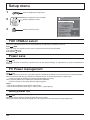
Setup menu ............................................................. 34
YUV/RGB-in select.................................................34
Power save ............................................................ 34
PC Power management ........................................ 34
Auto power off ....................................................... 34
OSD Language ...................................................... 35
3D Settings ............................................................ 35
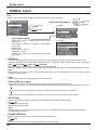
SIGNAL menu ....................................................... 36
Screensaver .......................................................... 37
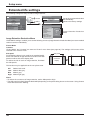
Extended life settings ............................................ 38
Customizing the Input labels ................................. 41
Options Adjustments ............................................. 42
3D Safety Precautions (To hide 3D Safety
Precautions) .......................................................... 44
Using FUNCTION button ........................................ 44
Troubleshooting ..................................................... 45
List of Aspect Modes ............................................. 46
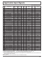
Applicable Input Signals ........................................ 47
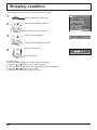
Shipping condition ................................................. 48
Specications ......................................................... 49
Safety Precautions
WARNING
Setup
This Plasma Display is for use only with the following optional accessories. Use with any other type of optional
accessories may cause instability which could result in the possibility of injury.
(All of the following accessories are manufactured by Panasonic Corporation.)
• Pedestal ......................................................................... TY-ST152UX1
• Mounting Bracket ........................................................... TY-WK152UX1
• HD-SDI Terminal Board with audio ................................ TY-FB10HD
• Dual Link HD-SDI Terminal Board .................................. TY-FB11DHD
• DVI-D Terminal Board .................................................... TY-FB11DD
Always be sure to ask a qualied technician to carry out set-up.
Small parts can present choking hazard if accidentally swallowed. Keep small parts away from young children. Discard
unneeded small parts and other objects, including packaging materials and plastic bags/sheets to prevent them from
being played with by young children, creating the potential risk of suffocation.
Do not place the Plasma Display on sloped or unstable surfaces.
• The Plasma Display may fall off or tip over.
Do not place any objects on top of the Plasma Display.
• If water is spills onto the Plasma Display or foreign objects get inside it, a short-circuit may occur which could result
in re or electric shock. If any foreign objects get inside the Plasma Display, please consult your local Panasonic
dealer.
Transport only in upright position!
• Transporting the unit with its display panel facing upright or downward may cause damage to the internal
circuitry.
Ventilation should not be impeded by covering the ventilation openings with items such as newspapers, table
cloths and curtains.
For sufcient ventilation;
If using the pedestal (optional accessory), leave a space of 20.0”/50 cm or more at the top, left, right and rear,
and also keep the space between the bottom of the display and the oor surface. If using some other setting-up
method, follow the manual of it. (If there is no specic indication of installation dimension in the installation
manual, leave a space of 20.0”/50 cm or more at the top, left and right; 12.0”/30 cm or more at the bottom; and
8.0”/20 cm or more at the rear.)
1
Safety Precautions
When using the Plasma Display
The Plasma Display is designed to operate on 200 - 240 V AC, 50/60 Hz.
Do not cover the ventilation holes.
• Doing so may cause the Plasma Display to overheat, which can cause re or damage to the Plasma Display.
Do not stick any foreign objects into the Plasma Display.
• Do not insert any metal or ammable objects into the ventilations holes or drop them onto the Plasma Display, as
doing so can cause re or electric shock.
Do not remove the cover or modify it in any way.
• High voltages which can cause severe electric shocks are present inside the Plasma Display. For any inspection,
adjustment and repair work, please contact your local Panasonic dealer.
Always use the breaker dedicated to the Plasma Display.
• Using other breakers may generate heat and cause re.
Do not turn on/off the breaker with wet hands.
• Doing so may cause electric shocks.
When using a fused load switch, make sure a fuse of appropriate capacity is used.
• Doing so may cause electric shocks.
Do not do anything that may damage the power cable.
• Do not damage the cable, make any modications to it, place heavy objects on top of it, heat it, place it near any
hot objects, twist it, bend it excessively or pull it. To do so may cause re and electric shock. If the power cable is
damaged, have it repaired at your local Panasonic dealer.
If the Plasma Display is not going to be used for any prolonged length of time, turn off the breaker.
To prevent the spread of re, keep candles or other open ames away from this product at all times.
If problems occur during use
If a problem occurs (such as no picture), or if smoke or an abnormal odour starts to come out from the Plasma
Display, immediately turn off the breaker.
• If you continue to use the Plasma Display in this condition, re or electric shock could result. After checking that
the smoke has stopped, contact your local Panasonic dealer so that the necessary repairs can be made. Repairing
the Plasma Display yourself is extremely dangerous, and shall never be done.
If water or foreign objects get inside the Plasma Display, if the Plasma Display is dropped, or if the cabinet
becomes damages, turn off the breaker.
• A short circuit may occur, which could cause re. Contact your local Panasonic dealer for any repairs that need to be made.
2
Safety Precautions
CAUTION
When using the Plasma Display
Do not bring your hands, face or objects close to the ventilation holes of the Plasma Display.
• Heated air comes out from the ventilation holes at the top of Plasma Display will be hot. Do not bring your hands
or face, or objects which cannot withstand heat, close to this port, otherwise burns or deformation could result.
Be sure to disconnect all cables before moving the Plasma Display.
• If the Plasma Display is moved while some of the cables are still connected, the cables may become damaged,
and re or electric shock could result.
Before cleaning, turn off the breaker for your safety.
• Electric shocks can result if this is not done.
Do not burn or breakup batteries.
• Batteries must not be exposed to excessive heat such as sunshine, re or the like.
This Plasma Display radiates infrared rays, therefore it may affect other infrared communication equipment.
Install your infrared sensor in a place away from direct or reected light from your Plasma Display.
Cleaning and maintenance
The front of the display panel has been specially treated. Wipe the panel surface gently using only a cleaning
cloth or a soft, lint-free cloth.
• If the surface is particularly dirty, wipe with a soft, lint-free cloth which has been soaked in pure water or water in
which neutral detergent has been diluted 100 times, and then wipe it evenly with a dry cloth of the same type until
the surface is dry.
• Do not scratch or hit the surface of the panel with ngernails or other hard objects, otherwise the surface may
become damaged. Furthermore, avoid contact with volatile substances such as insect sprays, solvents and thinner,
otherwise the quality of the surface may be adversely affected.
If the cabinet becomes dirty, wipe it with a soft, dry cloth.
• If the cabinet is particularly dirty, soak the cloth in water to which a small amount of neutral detergent has been
added and then wring the cloth dry. Use this cloth to wipe the cabinet, and then wipe it dry with a dry cloth.
• Do not allow any detergent to come into direct contact with the surface of the Plasma Display. If water droplets get
inside the unit, operating problems may result.
• Avoid contact with volatile substances such as insect sprays, solvents and thinner, otherwise the quality of the
cabinet surface may be adversely affected or the coating may peel off. Furthermore, do not leave it for long periods
in contact with articles made from rubber or PVC.
3
Safety Precautions
3D Safety Precautions
WARNING
Small Parts
3D Eyewear contains small parts (battery and specialised band, etc.) and must be kept out of reach of small
children to avoid accidental ingestion.
Disassembly
Do not disassemble or modify the 3D Eyewear.
Lithium Battery
Batteries must not be exposed to excessive heat such as sunshine, re or the like.
CAUTION
To enjoy 3D images safely and comfortably, please read these instructions fully.
Use for commercial applications and public viewing
Someone in authority should responsibly convey the precautions for use of the 3D Eyewear to the user.
3D Eyewear
Do not drop, exert pressure on, or step on the 3D Eyewear.
Always store the 3D Eyewear in the case provided when not in use.
Be careful of the tips of the frame when putting on the 3D Eyewear.
Be careful not to trap a nger in the hinge section of the 3D Eyewear.
Pay special attention when children are using the 3D Eyewear.
3D Eyewear should not be used by children younger than 5 - 6 years old, as a guideline.
All children must be fully supervised by parents or guardians who must ensure their safety and health
throughout the using 3D Eyewear.
4
Safety Precautions
Viewing 3D Content
Content for 3D viewing includes commercially available Blu-ray discs, 3D broadcasts, etc.
When preparing your own 3D content, ensure that it is properly produced.
Do not use the 3D Eyewear if you have a history of over-sensitivity to light, heart problems, or have any other
existing medical conditions.
Please stop using the 3D Eyewear immediately, if you feel tired, are not feeling well or experience any other
uncomfortable sensation.
Take an appropriate break after viewing a 3D movie.
Take a break of between 30 - 60 minutes after viewing 3D content on interactive devices such as 3D games
or computers.
Be careful not to strike the screen or other people unintentionally. When using the 3D Eyewear the distance
between the user and screen can be misjudged.
The 3D Eyewear must only be worn when viewing 3D content.
If you do not look toward the screen for a while when viewing 3D images, the 3D Eyewear may be turned off
automatically.
If you suffer from any eyesight problems (short / far-sighted, astigmatism, eyesight differences in left and
right), please ensure to correct your vision before using the 3D Eyewear.
Stop using the 3D Eyewear if you can clearly see double images when viewing 3D content.
Do not use the 3D Eyewear at a distance less than the recommended distance.
View from at least the recommended distance (3 times the effective height of the screen).
Recommended distance: 212.6”/5.4 m
When the top and bottom area of the screen is blackened, such as movies, view the screen at a distance
3 times further than the height of the actual image. (That makes the distance closer than above recommended
gure.)
3D Eyewear Use
Before using the 3D Eyewear, ensure no breakable objects surrounding the user to avoid any accidental
damage or injury.
Remove the 3D Eyewear before moving around to avoid falling or accidental injury.
Always put the 3D Eyewear in the case (supplied) after use.
Use the 3D Eyewear only for the intended purpose and nothing else.
Do not use 3D Eyewear in the condition of high temperature.
Do not use if the 3D Eyewear is physically damaged.
Do not use any devices that emit the infrared signals near the 3D Eyewear, as this may cause the 3D Eyewear
false operations.
Do not use devices (such as mobile phones or personal transceivers) that emit strong electromagnetic waves
near the 3D Eyewear as this may cause the 3D Eyewear to malfunction.
Stop using the 3D Eyewear immediately if a malfunction or fault occurs.
Stop using the 3D Eyewear immediately if you experience any redness, pain, or skin irritation around the nose
or temples.
In rare cases, the materials used in the 3D Eyewear may cause an allergic reaction.
Lithium Battery
Danger of explosion if battery is incorrectly replaced. Replace only with the same or equivalent type.
5
Accessories
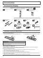
Accessories Supply
Check that you have the accessories and items shown
Operating Instruction book
Remote Control Transmitter
N2QAYB000560
Batteries for the Remote
Control Transmitter
(R6 (AA) Size × 2)
These accessories will be used by professional installers when they install the unit.
Fixing band × 3
TMME203
Nut cover × 3
(M20)
Nut cover × 3
(M16)
Bolt × 3
Power cable xing
plate A × 2
Power cable xing
plate B × 2
Allen wrench
Remote Control Batteries
Requires two R6 (AA) batteries.
1. Pull and hold the hook, then open the battery cover.
2. Insert batteries - note correct polarity ( + and -).
Close
Open
Hook
“R6 (AA)” size
Helpful Hint:
For frequent remote control users, replace old batteries with Alkaline
batteries for longer life.
Precaution on battery use
Incorrect installation can cause battery leakage and corrosion that will damage the remote control transmitter.
Disposal of batteries should be in an environment-friendly manner.
Observe the following precaution:
1. Batteries shall always be replaced as a pair. Always use new batteries when replacing the old set.
2. Do not combine a used battery with a new one.
3. Do not mix battery types (example: “Zinc Carbon” with “Alkaline”).
4. Do not attempt to charge, short-circuit, disassemble, heat or burn used batteries.
5. Battery replacement is necessary when remote control acts sporadically or stops operating the Plasma Display set.
6. Do not burn or breakup batteries.
Batteries must not be exposed to excessive heat such as sunshine, re or the like.
6
Connections
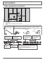
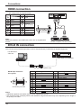
Video equipment connection
Cable xing
Secure any excess cables with band as required.
Note:
Three xing bands are supplied with this unit. In case of securing cables at six positions, please purchase it separately.
Pass the attached cable
xing band through the clip
as shown in the gure.
To secure cables connected to Terminals, wrap the cable xing band around them
then pass the pointed end through the locking block, as shown in the gure.
While ensuring there is sufcient slack in cables to minimize stress, rmly
bind all cables with the supplied xing band.
To tighten:
To loosen:
Push the catch
Pull
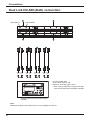
2
1
SERIAL
Control the Plasma
Display by connecting
to PC. (see page 12)
PC IN
PC Input
Terminal
(see page 11)
Pull
3D SHUTTER OUT
Connect the 3D IR
TRANSMITTER
(optional accessory).
AV IN (HDMI 1/2)
HDMI Input Terminal
(see page 10)
SDI IN 1-4 (4 systems)
4k2k signal Dual Link
HD-SDI input terminal
(see page 8)
DVI-D IN 1-4 (4 systems)
4k2k signal Single Link
DVI-D input terminal
(see page 9)
SLOT (DVI-D IN)
DVI-D Input Terminal (equivalent of DVI-D Terminal
Board (TY-FB11DD)) (see page 10)
It accepts the Terminal board (optional accessories).
(see page 1)
7
Connections
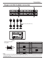
Dual Link HD-SDI (4k2k) connection
A
LINK A INPUT
B
LINK B INPUT
C
D
A
B
C
D
LINK A LINK B
OUT OUT
LINK A LINK B
OUT OUT
LINK A LINK B
OUT OUT
LINK A LINK B
OUT OUT
1ch
2ch
3ch
4ch
• Recommended cable
75 coaxial cable 5C-FB
• Maximum extended length: 100 m
* When using a cable with a length of less than
100 m and an attenuation of 20 dB at 750 MHz
Hardware with Dual Link HD-SDI output
capability
Note:
Additional equipment and cables shown are not supplied with this set.
8
Connections
Single Link DVI-D (4k2k) connection
A
B
A
B
C
D
C
D
DVI-video cable (Within 5 m)
1ch
2ch
3ch
4ch
Hardware with Single Link DVI-D output
capability
DVI-D Input Connector
Pin Layouts
1
Pin No.
8
9
16
17
24
Connection port view
1
2
3
4
5
6
7
8
9
10
11
12
Signal Name
T.M.D.S. data 2T.M.D.S. data 2+
T.M.D.S. data 2 shield
DDC clock
DDC data
T.M.D.S. data 1T.M.D.S. data 1+
T.M.D.S. data 1 shield
Pin No.
13
14
15
16
17
18
19
20
21
22
23
24
Signal Name
+5 V DC
Ground
Hot plug detect
T.M.D.S. data 0T.M.D.S. data 0+
T.M.D.S. data 0 shield
T.M.D.S. clock shield
T.M.D.S. clock+
T.M.D.S. clock-
Notes:
• Additional equipment and cables shown are not supplied with this set.
• Use the DVI-D cable complying with the DVI standard. Image deterioration may occur depending on the length or
the quality of the cable.
9
Connections
HDMI connection
[Pin assignments and signal names]
Pin No.
1
2
3
4
5
6
7
8
9
10
Signal name
T.M.D.S Data2+
T.M.D.S Data2
Shield
T.M.D.S Data2T.M.D.S Data1+
T.M.D.S Data1
Shield
T.M.D.S Data1T.M.D.S Data0+
T.M.D.S Data0
Shield
T.M.D.S Data0T.M.D.S Clock+
Pin No.
11
Signal name
T.M.D.S Clock
Shield
12
T.M.D.S Clock-
13
CEC
14
Reserved
(N.C. on device)
15
16
19
SCL
SDA
DDC/CEC
Ground
+5V Power
Hot Plug Detect
17
18
19
3 1
HDMI cables
18
4 2
HDMI
AV OUT
Note:
Additional equipment and HDMI cable shown are not supplied with
this set.
HDMI
AV OUT
DVD Player or SET-TOP-BOX
(HDMI compatible machines only)
DVI-D IN connection
This unit has terminal boards equivalent to DVI-D Terminal Board (TY-FB11DD) as standard equipment.
PC with DVI-D
video out
Audio Input is not available.
DVI-video cable (Within 5 m)
DVI-D Input Connector
Pin Layouts
24
Pin No.
17
9
16
8
1
Connection port view
1
2
3
4
5
6
7
8
9
10
11
12
Signal Name
T.M.D.S. data 2T.M.D.S. data 2+
T.M.D.S. data 2 shield
DDC clock
DDC data
T.M.D.S. data 1T.M.D.S. data 1+
T.M.D.S. data 1 shield
Pin No.
13
14
15
16
17
18
19
20
21
22
23
24
Signal Name
+5 V DC
Ground
Hot plug detect
T.M.D.S. data 0T.M.D.S. data 0+
T.M.D.S. data 0 shield
T.M.D.S. clock shield
T.M.D.S. clock+
T.M.D.S. clock-
Notes:
• Additional equipment and cables shown are not supplied with this set.
• Use the DVI-D cable complying with the DVI standard. Image deterioration may occur depending on the length or
the quality of the cable.
10
Connections
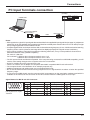
PC Input Terminals connection
(Female)
COMPUTER
Conversion adapter
(if necessary)
RGB
Mini D-sub 15p
PC cable
(Male)
Notes:
• With regard to the typical PC input signals that are described in the applicable input signals list (see page 47), adjustment
values such as for the standard picture positions and sizes have already been stored in this unit. You can add up to eight
PC input signal types that are not included in the list.
• Computer signals which can be input are those with a horizontal scanning frequency of 15 to 110 kHz and vertical scanning
frequency of 48 to 120 Hz. (However, the image will not be displayed properly if the signals exceed 1,200 lines.)
• If the number of pixels of input signal exceeds the following maximums, it may not be possible to show the ne
detail with sufcient clarity. (SXGA compatible)
For vertical: 1,080 dots
For horizontal: 1,440 dots when the aspect mode is set to “4:3”
1,920 dots when the aspect mode is set to “16:9”
• The PC input terminals are DDC2B-compatible. If the computer being connected is not DDC2B-compatible, you will
need to make setting changes to the computer at the time of connection.
• Some PC models cannot be connected to the set.
• There is no need to use an adapter for computers with DOS/V compatible Mini D-sub 15P terminal.
• The computer shown in the illustration is for example purposes only.
• Additional equipment and cables shown are not supplied with this set.
• Do not set the horizontal and vertical scanning frequencies for PC signals which are above or below the specied
frequency range.
• To use sync input VBS signals, use the connector which incorporates a 75-ohm termination resistance and which is
available on the market, for the connection of the HD connector where the VBS signals are to be input.
Signal Names for Mini D-sub 15P Connector
5
4
10 9
3
2
8
1
7
6
15 14 13 12 11
Pin Layout for PC Input
Terminal
Pin No.
Signal Name
Pin No.
Signal Name
Pin No.
Signal Name
1
R
6
GND (Ground)
11
NC (not connected)
2
G
7
GND (Ground)
12
SDA
3
B
8
GND (Ground)
13
HD/SYNC
4
NC (not connected)
9
+5 V DC
14
VD
5
GND (Ground)
10
GND (Ground)
15
SCL
11
Connections
SERIAL Terminals connection
The SERIAL terminal is used when the Plasma Display is controlled by a computer.
COMPUTER
(Male)
RS-232C Straight cable
(Female)
9
5
D-sub 9p
Notes:
• Use the RS-232C straight cable to connect the computer to the Plasma Display.
• The computer shown is for example purposes only.
• Additional equipment and cables shown are not supplied with this set.
8
4
7
3
6
2
1
Pin layout for SERIAL Terminal
The SERIAL terminal conforms to the RS-232C interface
specication, so that the Plasma Display can be controlled
by a computer which is connected to this terminal.
The computer will require software which allows the
sending and receiving of control data which satisfies
the conditions given below. Use a computer application
such as programming language software. Refer to the
documentation for the computer application for details.
Signal names for D-sub 9P connector
Communication parameters
These signal names are those of computer specications.
Signal level
Synchronization method
Baud rate
Parity
Character length
Stop bit
Flow control
RS-232C compliant
Asynchronous
9600 bps
None
8 bits
1 bit
-
Basic format for control data
The transmission of control data from the computer
starts with a STX signal, followed by the command, the
parameters, and lastly an ETX signal in that order. If there
are no parameters, then the parameter signal does not
need to be sent.
STX
C1 C2 C3
Start
(02h)
:
P1 P2 P3 P4 P5
ETX
Colon
Parameter(s)
(1 - 5 bytes)
3-character
command (3 bytes)
End
(03h)
Notes:
• If multiple commands are transmitted, be sure to wait for
the response for the rst command to come from this unit
before sending the next command.
• If an incorrect command is sent by mistake, this unit will
send an “ER401” command back to the computer.
12
Pin No.
2
3
5
4 • 6
7
8
1 • 9
Details
RXD
TXD
GND
Non use
(Shorted in this set)
NC
Command
Command
PON
POF
IMS
DAM
Parameter
None
None
None
SL1
SD1
DV1
HM1
HM2
PC1
None
ZOOM
FULL
JUST
NORM
ZOM2
ZOM3
SJST
SNOM
SFUL
14:9
Control details
Power ON
Power OFF
Input select (toggle)
SLOT input (SLOT INPUT)
SDI IN input (4K-SDI)
DVI-D IN input (4K-DVI)
HDMI 1 input (HDMI1)
HDMI 2 input (HDMI2)
PC IN input (PC)
Screen mode select (toggle)
Zoom1 (For Video/SD/PC
signal)
16:9
Just (For Video/SD signal)
4:3 (For Video/SD/PC signal)
Zoom2 (For HD signal)
Zoom3 (For HD signal)
Just (For HD signal)
4:3 (For HD signal)
4:3 Full (For HD signal)
14:9
With the power off, this display responds to PON
command only.
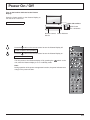
Power On / Off
Turn on the breaker dedicated to the Plasma
Display.
Press the Power switch on the Plasma Display to
turn the set on: Power-On.
Power Indicator: Green
Right side surface
Main Power
On / Off Switch
Remote Control
Sensor
Press the
Power Indicator
button on the remote control to turn the Plasma Display off.
Power Indicator: Red (standby)
Press the
button on the remote control to turn the Plasma Display on.
Power Indicator: Green
Turn the power to the Plasma Display off by pressing the
unit, when the Plasma Display is on or in standby mode.
switch on the
Note:
During operation of the power management function, the power indicator turns
orange in the power off state.
13
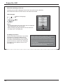
Power On / Off
When rst switching on the unit
Following screen will be displayed when the unit is turned on for the rst time.
Select the items with the remote control. Unit buttons are invalid.
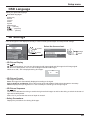
OSD Language
1
OSD Language
Select the language.
English (UK)
Deutsch
2
Set.
Français
Italiano
Español
ENGLISH (US)
Notes:
• Once the language is set, this screen won’t be displayed
when switching on the unit next time.
• After the setting, language selection can be done from
the Setup menu. (see page 35)
3D Safety Precautions
Activate 3D Safety Precautions if you deliver
3D images to unspecied audiences for
business or other purposes. The 3D Safety
Precautions will be displayed every time the
power is turned on, if you set the “3D Safety
Precautions” on the Options menu to “On”.
(see page 44)
14
Select
Set
When 3D images will be viewed by unspecied number of
people or used for commercial applications, someone in
authority should convey the following precautions.
These precautions should be followed in the home as well.
3D Viewing/ 3D Content/ Viewing distance/ 3D Eyewear
recommendations
- To enjoy 3D images safely and comfortably, please
read the Operating Instructions fully.
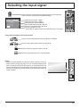
Selecting the input signal
Press to select the input signal to be played back from the equipment
which has been connected to the Plasma Display.
INPUT
HDMI1
HDMI2
SLOT INPUT
4K-SDI
4K-DVI
PC
HDMI input terminal in HDMI 1.
HDMI input terminal in HDMI 2.
Input terminal in Terminal Board.*
4k2k HD-SDI input terminal in SDI IN.
4k2k DVI-D input terminal in DVI-D IN.
PC input terminal in PC IN.
* “SLOT INPUT” appears when the Terminal Board is connected.
Using dedicated buttons for input selection
Press to select HDMI signal terminals in HDMI 1 or HDMI 2.
Press to select 4k2k signal in SDI IN or DVI-D IN.
Press to select PC signal terminal in PC IN.
Press to select Input terminal in Terminal Board.
Notes:
• Selecting is also possible by pressing the INPUT button on the unit.
• Image retention (image lag) may occur on the plasma display panel
when a still picture is kept on the panel for an extended period. The
function that darkens the screen slightly is activated to prevent image
retention (see page 45), but this function is not the perfect solution to
image retention.
ENTER/
MENU
INPUT
15
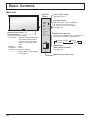
Basic Controls
Main Unit
Right side
surface
ENTER/
Remote control sensor
Power Indicator
The Power Indicator will light.
• Power-OFF .... Indicator not illuminated (The
unit will still consume some
power as long as the power
supply is connected to the
unit.)
• Standby ........ Red
• Power-ON ...... Green
• PC Power management (DPMS)
.........................Orange (With PC input signal.
See page 34)
Enter / Aspect button
(see page 18, 21)
Up / Down button
When the menu screen is displayed:
: press to move the cursor up
: press to move the cursor down
(see page 21)
MENU
INPUT
MENU Screen ON / OFF
Each time the MENU button is pressed, the
menu screen will switch. (see page 21)
Normal Viewing
Pos. /Size
Picture
Setup
INPUT button
(INPUT signal selection)
(see page 15)
Main Power On / Off Switch
16
Basic Controls
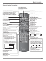
Remote Control Transmitter
AUTO SETUP button
Automatically adjusts the
position/size of the screen.
(see page 22)
Standby (ON / OFF) button
The Plasma Display must rst be turned
on at the power switch (see page 13).
Press this button to turn the Plasma
Display On, from Standby mode. Press
it again to turn the Plasma Display Off
to Standby mode.
LIGHT button
The remote control’s buttons illuminate.
HDMI buttons
Press to select HDMI 1 or HDMI 2
input. (see page 15)
PICTURE button
(see page 25)
OK button
Press to make selections.
PC button
Press to select PC IN input.
(see page 15)
SDI button, DVI button
Press to select SDI IN or DVI-D IN
input. (see page 15)
SETUP button
(see page 34)
POS. /SIZE button
(see page 22)
RETURN button
(see page 21)
Press the RETURN button to return
to previous menu screen.
Cursor buttons
N button
(see page 24, 25, 27)
INPUT button
Press to select input signal sequentially.
(see page 15)
RECALL button
Press the “RECALL” button to display
the current system status.
1 Input label
2 Aspect mode (see page 18)
During 3D images (see page 35)
Prole name (see page 32)
NANODRIFT Saver operating
(see page 39)
3 Off timer
The off timer indicator is displayed
only when the off timer has been set.
1
PC
3D
SLOT buttons
Press to select SLOT Terminal Board.
(see page 15)
4:3
Memory name: MEMORY2
NANODRIFT
2
FUNCTION buttons
(see page 44)
VIDEO MENU button
Press to select Picture Mode.
(see page 25)
Normal
Monitor
EXIT button
Exits from Menu screen.
OFF TIMER button
The Plasma Display can be preset
to switch to stand-by after a xed
period. The setting changes to 30
minutes, 60 minutes, 90 minutes
and 0 minutes (off timer cancelled)
each time the button is pressed.
30
Off timer
90
ASPECT button
Press to adjust the aspect.
(see page 18)
3
Dynamic
Cinema
60
90
0
When three minutes remain, “Off
timer 3” will ash.
The off timer is cancelled if a
power interruption occurs.
Numeric buttons
(see page 32)
MEM. LOAD button
(see page 32)
17
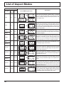
ASPECT Controls
The Plasma Display will allow you to enjoy viewing the picture at its maximum size, including wide screen cinema
format picture.
Press repeatedly to move through the aspect options:
For details about the aspect mode, please see “List of Aspect Modes” (page 46).
[from the unit]
Right side surface
ENTER/
The aspect mode changes each time the ENTER button is pressed.
Aspect Mode
You can select the aspect mode from the following 3 modes. Make the mode setting in “Aspect Mode”
of the Options menu. (see page 43)
Mode1, Mode2, All Aspect
The factory setting is “Mode1”.
[Aspect mode for 3D images and 4k2k signal]
The aspect is xed as “16:9” and you cannot switch.
Mode1 (Factory setting)
For PC signal input:
4:3
Zoom
16:9
For SD signal input (525 (480) / 60i • 60p, 625 (575) / 50i • 50p):
4:3
Zoom1
Zoom2
Zoom3
16:9
14:9
Just
For HD signal input [1125 (1080) / 60i • 50i • 60p • 50p • 24p • 25p • 30p • 24sF, 1250 (1080) / 50i,
750 (720) / 60p • 50p]:
4:3
Just
4:3 Full
14:9
Zoom1
16:9
Zoom2
Zoom3
Mode2
For PC signal input:
4:3
Zoom
16:9
For SD signal input (525 (480) / 60i • 60p, 625 (575) / 50i • 50p):
4:3
Zoom
16:9
Just
For HD signal input [1125 (1080) / 60i • 50i • 60p • 50p • 24p • 25p • 30p • 24sF, 1250 (1080) / 50i,
750 (720) / 60p • 50p]:
4:3
4:3 Full
Zoom
16:9
Just
All Aspect
For PC signal input:
4:3
Zoom
16:9
For SD signal input (525 (480) / 60i • 60p, 625 (575) / 50i • 50p):
4:3
Zoom1
Zoom2
Zoom3
16:9
14:9
Just
For HD signal input [1125 (1080) / 60i • 50i • 60p • 50p • 24p • 25p • 30p • 24sF, 1250 (1080) / 50i, 750 (720) / 60p • 50p]:
4:3 Full
Zoom1
Zoom2
Zoom3
16:9
14:9
Just1
Just2
4:3 (1)
4:3 (2)
Notes:
• Be aware that if you put the display in a public place for commercial purposes or a public showing and then use the
aspect mode select function to shrink or expand the picture, you may be violating the copyright under copyright law.
It is prohibited to show or alter the copyrighted materials of other people for commercial purposes without the prior
permission of the copyright holder.
• The aspect mode is memorized separately for each input terminal.
• Do not allow the picture to be displayed in 4:3 mode for an extended period, as this can cause a permanent image
retention to remain on the Plasma Display Panel.
18
Viewing 3D images
You can enjoy viewing 3D images with contents or programmes compatible with 3D effect by using the 3D eyewear
(optional).
Note:
You need the 3D IR TRANSMITTER (optional) and the 3D eyewear (optional) to view the 3D images on this display.
For further information, see the instruction manuals of the 3D IR TRANSMITTER and the 3D eyewear.
This display supports “Frame Sequential*1”, “Side by Side*2” and “Top and Bottom*3” 3D formats.
*1: The 3D format that the images for the left and right eyes are recorded with the high denition quality and alternately played back
*2, *3: Other available 3D formats
To view the 3D images
To view the contents of the Frame Sequential format (ex. 3D-compatible Blu-ray Disc, etc.) with 3D effect
Connect the 3D-compatible player via an HDMI cable (see page 10) and playback the contents.
• Use fully wired HDMI compliant cable.
• For the settings of the player, read the manual of the player.
• If you use the non 3D-compatible player, the images will be displayed without 3D effect.
To view the contents of 3D formats other than Frame Sequential with 3D effect.
Match the picture format in “3D Picture Format” (see page 35) before viewing.
• You can view “Side by Side” and “Top and Bottom” with 3D effect even if you use the non 3D-compatible player.
• Please consult the suppliers of contents or programmes for availability of this service.
Turn the 3D Eyewear on
• See the instruction manual of 3D eyewear for handling.
Put on the 3D Eyewear
Watch the 3D images
Note:
• If the room is lit by uorescent lights (50 Hz) and light appears to icker when using the 3D Eyewear, switch off the
uorescent light.
• 3D content will not be correctly visible if the 3D Eyewear is worn upside down or back-to-front.
• Do not wear the 3D Eyewear when watching anything other than 3D images. Liquid crystal displays (such as
computer screens, digital clocks or calculators, etc.) may be difcult to see while wearing the 3D Eyewear.
• Do not use the 3D Eyewear as sunglasses.
• 3D effects may be perceived differently depending on the person.
19
Viewing 3D images
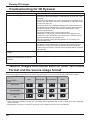
Troubleshooting for 3D Eyewear
Symptoms
Checks
Cannot see 3D images
3D Eyewear is turned off automatically
There is something wrong with the 3D
images
The indicator lamp does not light when
pressing the power button on the 3D
Eyewear
• Has the 3D Eyewear been switched On?
• Ensure that “3D Picture Display” in “3D Settings” is set to “3D”. (see
page 35)
• Some 3D image signals may not be automatically recognized as 3D
images. Set “3D Picture Format” in “3D Settings” to match the picture
format. (see page 35)
• Check that there are no obstacles between the infrared sensors on
the display and the 3D Eyewear. If the 3D Eyewear stops receiving
the infrared signal for about 5 minutes, the 3D Eyewear will be
turned off automatically.
• Check the available area to use the 3D Eyewear.
• Depending on the person, the 3D images may be difcult to see,
or cannot be seen, especially in users that have a different level of
eyesight between the left and right eyes.
Take the necessary steps (wearing glasses etc.) to correct your
eyesight before use.
• Check that there are no obstacles between the infrared sensors on
the display and the 3D Eyewear or that the 3D Eyewear is placed
inside the coverage area. If the 3D Eyewear stops receiving the
infrared signal for about 5 minutes, the 3D Eyewear will be turned off
automatically.
• Check the setting of “3D Picture Sequence”. (see page 35)
• The battery may be running low or at. Replace it.
Table of images that can be seen for each 3D Picture
Format and the source image format
If the picture appears to be abnormal, refer to the table below to choose the correct 3D picture format setting.
3D Picture Format
Source image
format
Auto
Side by Side
*1
Normal*2
Top and Bottom
Native
Side by side
Top and bottom
*1
Normal*2
Normal format
(2D)
Normal
*1
Normal
When the source image is not recognized correctly
When “3D Picture Display” is set to “3D”, the images will be displayed with 3D effect. When set to “2D”, displayed
without 3D effect.
• Depending on the player or contents, the image may be different from the above illustrations.
*2
20
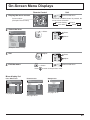
On-Screen Menu Displays
Remote Control
Unit
1 Display the menu screen.
MENU
Press to select.
(Example: Picture menu)
Press several times.
Each time the MENU button is pressed, the
menu screen will switch.
Normal Viewing
Picture
Setup
Pos. /Size
2 Select the item.
Select.
Picture
Press.
ENTER/
Normalise
Normal
Picture Mode
Contrast
Brightness
Colour
Hue
Sharpness
White balance
Advanced settings
Normal
25
0
0
0
5
Select.
Normal
Memory save
Memory load
Memory edit
(Example: Picture menu)
Adjust.
3 Set.
Press.
ENTER/
Adjust.
4 Exit the menu.
MENU
Press.
Press
Press several times.
to return to the previous menu.
Menu display list
Pos. /Size menu
Normalise
Auto Setup
H-Pos
H-Size
V-Pos
V-Size
Dot Clock
Clock Phase
Clamp Position
Over scan
Scaling Mode
Picture menu
Setup menu
Picture
Pos. /Size
Normal
Normalise
Picture Mode
Contrast
Brightness
Colour
Hue
Sharpness
White balance
Advanced settings
0
0
0
0
0
0
0
see page 22-24
Setup
Normal
Off
HV-Fit
Normal
25
0
0
0
5
Memory save
Memory load
Memory edit
Normal
3D Settings
Signal
Screensaver
Extended life settings
Input label
Power save
Off
PC Power management
Off
Auto power off
Off
OSD Language
English (UK)
see page 34-41
see page 25-33
21
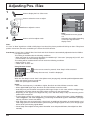
Adjusting Pos. /Size
1
Press to display the Pos. /Size menu.
2
Press to select the menu to adjust.
3
Press to adjust the menu.
4
Press to exit from adjust mode.
Pos. /Size
Normalise
Auto Setup
H-Pos
H-Size
V-Pos
V-Size
Dot Clock
Clock Phase
Clamp Position
Over scan
Scaling Mode
Normal
0
0
0
0
0
0
0
Off
HV-Fit
Note:
Unadjustable items are grayed
out.
Adjustable items differ depending
on the input signal and the
display mode.
Note:
If a “Cue” or “Rew” signal from a VCR or DVD player is received, the picture position will shift up or down. This picture
position movement cannot be controlled by the Picture Pos./Size function.
Auto Setup H-Pos/V-Pos, H-Size/V-Size, Dot Clock and Clock Phase are automatically adjusted when the RGB or
PC signal is received.
This setting is enabled under the following conditions:
• When the signal is not PC format, this setting is enabled only if “Over scan” (see page 23) is “Off”, and
H-Size/V-Size is not automatically adjusted.
This setting will be invalid and will not work under the following conditions:
• Aspect is set to “Just”
• “Under scan” is set to “On”
Using Remote Control
When
on the remote control is pressed, “Auto Setup” will be executed.
When Auto Setup does not work, “Invalid” is displayed.
Auto mode
When the “Auto Setup“ is set to “Auto” in the Options menu (see page 43), automatic position adjustment starts:
• When the display power is turned ON.
• When the input signal is switched.
Notes:
• If the dot clock frequency is 162 MHz or higher, Dot Clock and Clock Phase cannot be made.
• When digital RGB signal input, Dot Clock and Clock Phase cannot be made.
• Auto Setup may not work when a cropped or dark image is input. In such case, switch to a bright image
with borders and other objects are clearly shown, and then try auto setup again.
• Depending on the signal, out of alignment may occur after Auto Setup. Carry out ne tuning for the
position/size as required.
• If Auto Setup cannot set properly for vertical frequency 60Hz XGA signal (1024×768@60Hz,
1280×768@60Hz, and 1366×768@60Hz), pre-selecting the individual signal in “XGA Mode” (see page
36) may results in correct Auto Setup.
• Auto Setup does not work well when a signal such as additional information is superimposed out of
valid image period or intervals between synchronizing and image signals are short, or for image signal
with tri-level synchronizing signal added.
• If Auto Setup cannot adjust correctly, select “Normalise” once and press OK button, then adjust Pos. /Size
manually.
22
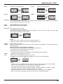
Adjusting Pos. /Size
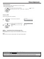
H-Pos
Adjust the horizontal position.
V-Pos
Adjust the vertical position.
H-Size
Adjust the horizontal size.
V-Size
Adjust the vertical size.
Dot Clock
(During RGB and PC input signal)
Periodic striped pattern interference (noise) may occur when a striped pattern is displayed. If this happens,
adjust so that any such noise is minimized.
Clock
Phase
(During RGB and PC input signal)
Eliminate the ickering and distortion.
Over scan Turn image over scan On/Off.
Congurable signals are as follows:
525i, 525p, 625i, 625p, 750/60p, 750/50p, 1125 (1080) / 50i · 60i · 24sF · 24p · 25p · 30p · 50p · 60p,
1250 (1080) / 50i (RGB, DVI, SDI, HDMI)
On
Off
Notes:
• When “Off” is set, “H-Size” and “V-Size” cannot be adjusted.
• When the “Under scan” is set to “On”, this setting will be invalid.
Clamp
Position
Under
scan
(During RGB input signal)
Adjusts the clamp position when black parts of the image have no detail due to underexposure or are
tinged with green.
Optimum value for Clamp Position adjustment
When black parts have no detail due to underexposure (blackout)
Value that causes least blackout is the optimum.
When black parts are tinged with green
Value that cancels the greenishness without causing blackout is the optimum.
Adjusts the image display size on screen.
Off: Sets the normal image display size on screen.
On: Sets the image display size approximately 95 % of the normal image display.
Off
On
Notes:
• “Under scan” can be modified when “Studio mode” in the Options menu is “On”. When “Studio
mode” is “Off”, this setting is “Off” and cannot be changed. (see page 43)
• This setting is valid only when the input signals are as follows;
525i, 525p, 625i, 625p, 750/60p, 750/50p, 1125/60i, 1125/50i, 1125/24sF, 1125/25p, 1125/24p,
1125/30p, 1125/60p, 1125/50p, 1250/50i (RGB, DVI, SDI, HDMI)
• When “Under scan” is set to “On”, “H-Pos” and “V-Pos” in “Pos. /Size” can be adjusted.
• Refer to each board’s operating instruction for DVI, SDI’s corresponding signals.
23
Adjusting Pos. /Size
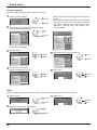
Scaling
Mode
Selects the pattern to display the 1920 x 1080 (16:9) image on the 4096 x 2160 (17:9) display.
The image size is adjusted according to the aspect mode and is enlarged horizontally or vertically,
or its sides are masked.
Example: Aspect is 16:9
Scaling Mode
Vertically
enlarged
Horizontally
enlarged
Side masking
H-Fit
V: 16/15 times
H: 16/15 times
Not adjusted
V-Fit
V: Same size
H: Same size
Adjusted
HV-Fit
V: Same size
H: 16/15 times
Not adjusted
Image
Note:
When the input signal is a 4k2k or 2k1k signal, the setting is cancelled.
Helpful Hint (
/
Normalise
Normalisation)
While the Pos. /Size display is active, if either the N button on the remote control is pressed at any time or the OK
button is pressed during “Normalise”, then all adjustment values are returned to the factory settings.
24
Picture Adjustments
1
2
Press to display the Picture menu.
Select to adjust each item.
Press to select the menu to adjust.
Select the desired level by looking at the picture behind the menu.
Note:
Menu that cannot be adjusted is grayout. Adjustable menu changes depending on signal,
input and menu setting.
Picture
Normalise
Press “ ” or “ ” button to switch between modes.
Dynamic
Normal
Cinema
Monitor
Normal
Normal
Picture Mode
Contrast
Brightness
Colour
Hue
Sharpness
White balance
Advanced settings
25
0
0
0
5
Normal
For viewing in standard (evening lighting) environments.
This menu selects the normal levels of
Brightness and Contrast.
Normal
Dynamic
For viewing in brighter environments.
This menu selects higher than normal levels of
Brightness and Contrast.
Cinema
Ideal for movies.
Press to enter
Advanced settings.
Advanced settings
Enables ne picture adjustment at a professional
level (see next page).
Advanced settings
Normalise
Normal
0
0
Black extension
Input level
Gamma
W/B High R
W/B High G
W/B High B
W/B Low R
W/B Low G
W/B Low B
Cinema reality
Studio Gain
Noise reduction
Colour Gamut
Helpful Hint (
2.2
0
0
0
0
0
0
Monitor
For use when creating broadcast or movie content.
With this picture, even if the overall average picture
level (APL) changes, the brightness of areas with
the same signal level does not change.
Notes:
• When “Monitor” is selected in Picture Mode, the
following menu items cannot be set.
Picture menu: Contrast
Extended life settings: Peak limit (see page 38)
Setup menu: Power save (see page 34)
• If you would like to change the picture and colour of
the selected Picture menu to something else, adjust
using the items in the Picture menu. (see next page)
Press “ ” or “ ” button to switch between modes.
Off
Off
Off
Normal
Cool
Warm
Studio*
Warm2
Warm3
* “Studio” can be modified when “Studio mode”
in the Options menu is “On”. (see page 43)
Normal: Intermediate color temperature.
Warm: Colors with a reddish tinge.
Warm2: Colors with a reddish tinge (6100K).
Warm3: Colors with a reddish tinge (5600K).
Studio: Optimal color temperature for studio viewing (3200K).
Cool: Colors with a bluish tinge.
/
Normalise
Normalisation)
While the “Picture” menu is displayed, if either the N button on the remote control is pressed at any time or the OK
button is pressed during “Normalise”, then all adjustment values are returned to the factory settings.
25
Picture Adjustments
Item
Contrast
Brightness
Colour
Hue
Sharpness
Effect
Less
Adjustments
More
Darker
Brighter
Less
More
Reddish
Greenish
Less
More
Selects the proper brightness
and density for the room.
Adjusts for easier viewing of
dark pictures such as night
scenes and black hair.
Adjusts colour saturation.
Notes:
• You can change the level of each function
(Contrast, Brightness, Colour, Hue, Sharpness)
for each Picture Mode.
• The setting details for Normal, Dynamic,
Cinema and Monitor respectively are memorized
separately for each input terminal.
• In Contrast, there is not a noticeable change
even when contrast is increased with a bright
picture or reduced with a dark picture.
Adjusts for nice skin colour.
Adjusts picture sharpness.
Advanced settings
Notes:
• The adjustment values are memorized separately for each input terminal.
• The adjustment range values should be used as an adjustment reference.
Item
Black
extension
Input level
Gamma
Effect
Details
Less
More
Less
More
Down
Up
“W/B”
adjustment
Less
More
Cinema
reality
Off
On
Studio
Gain
Off
On
26
Adjusts the dark shades of the image in gradation.
Adjustment of parts which are extremely bright and hard to see.
S Curve
2.0
2.2
2.6
W/B High R/G/B: Adjusts the white balance for light red, light green or light blue
areas.
W/B Low R/G/B: Adjusts the white balance for dark red, dark green or dark blue
areas.
Carry out “W/B” adjustment as follows.
1. Adjust the white balance of the bright sections using the “W/B High R”, “W/B
High G” and “W/B High B” settings.
2. Adjust the white balance of the dark sections using the “W/B Low R”, “W/B
Low G” and “W/B Low B” settings.
3. Repeat steps 1 and 2 to adjust.
Steps 1 and 2 affect each other’s settings, so repeat each step in turn to
make the adjustment.
When “on”, the display attempts to reproduce a more natural interpretation of
sources such as movie pictures, which are recorded at 24 frames per second. If
the picture is not stable, turn the setting to “off”.
Note:
When On, this setting only affects the following signal input:
525i (480i), 625i (575i), 1125 (1080) / 60i
Sharpens the contrast for a better view when a part of the image is too light to
see.
Off: Disables “Studio Gain”.
On: Enables “Studio Gain”.
Notes:
• “Studio Gain” can be modied when “Studio mode” in the Options menu is
“On”. When “Studio mode” is “Off”, this setting is “Off” and cannot be changed.
(see page 43)
• This setting is valid only when the input signals are as follows:
RGB (analog), SDI, HDMI
Picture Adjustments
• Noise reduction
Sets the following three NR (Noise Reduction) functions together.
P-NR, Mosquito NR, Block NR
(
Press to select “Noise reduction”.
Noise reduction
)
Off
Press to select “Off”, “Min” , “Mid” , “Max” , “Advanced”.
Advanced NR
Sets the three NR functions separately.
1
2
Press to select “Advanced”.
Noise reduction
P-NR
Block NR
Mosquito NR
Advanced
Off
Off
Off
Press to select P-NR, Mosquito NR
or Block NR.
Press to select “Off”, “Min”, “Mid”,
“Max”.
Noise reduction
P-NR
Block NR
Mosquito NR
Advanced
Off
Off
Off
P-NR:
Automatically reduces unwanted picture noise.
Block NR: Reduces block noise when playing MPEG videos.
Mosquito NR: Reduces mosquito noise around subtitles on MPEG videos.
Note:
Noise reduction cannot be adjusted while a PC signal is being applied.
Helpful Hint (
/
Normalise
Normalisation)
On the remote control unit, while the “Advanced settings” menu is displayed, if either the N button is pressed at any time or
the OK button is pressed during “Normalise”, then all adjustment values are returned to the factory settings.
27
Picture Adjustments
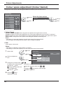
Colour space adjustment (Colour Gamut)
Changes the colour space to BT.709 signal standard chromaticity point and ne-tunes it.
Advanced settings
Normalise
Normal
Black extension
Input level
Gamma
W/B High R
W/B High G
W/B High B
W/B Low R
W/B Low G
W/B Low B
Cinema reality
Studio Gain
Noise reduction
Colour Gamut
0
0
2
access
Select the item and set.
Colour Gamut
2.2
0
0
0
0
0
0
1
2
change
1
select
Native
Colour Gamut
select
Off
Off
Off
Colour Gamut
DIGITAL CINEMA COLOUR: Sets color gamut to reproduce the original color of movies.
Custom: Enables the colour space adjustment, the colour space adjustment set in the “EDIT” is reected.
Native: Disables the colour space adjustment, images are displayed in the original colour gamut of the panel.
HDTV Colour: Changes the colour space to BT.709 signal standard chromaticity point.
Notes:
• This setting is memorized separately for each input terminal and “Picture Mode”.
• For 3D images, this setting becomes “Native” and no setting is available.
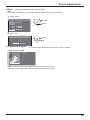
Edit
Colour space is ne-tuned.
Notes:
• This setting is valid when “Colour Gamut” is “Custom”.
• This setting is memorized separately for each input terminal and “Picture Mode”.
1
2
2
access
1
select
Select “Edit”.
Select an adjustment
item.
select
3
Change the numerical value.
[To adjust with the button]
Press the
button.
Change the numerical value
with the button.
Press the
button.
4
Press the
button.
Adjustment is ended.
28
Colour Gamut
Custom
Colour Gamut
Edit
R Ratio
G Ratio
B Ratio
R
65535
2110
0
G
2900
65535
1760
Reset
65535
[To input the numerical value directly]
Input the numerical value from
Pressing the
Press the
to
will cancel the value change.
button.
B
0
0
65535
Picture Adjustments
Reset
Resets the adjustment value of colour space.
Note:
This setting is reected only for the selected input terminal and the “Picture Mode”.
1
Select “Reset”.
Colour Gamut
Colour Gamut
Edit
R Ratio
G Ratio
B Ratio
2
access
1
select
1
select
2
set
Custom
R
G
B
65535
2110
0
2900
65535
1760
0
0
65535
Reset
2
Select “Ok”.
Colour Gamut
Reset
Ok
Cancel
Chromaticity diagram
The RGB triangle representing current colour space is shown.
Colour Gamut: Custom
— Native
— Custom
y
x
White line: Colour gamut with “Native” setting (original colour gamut.)
Yellow line: Colour gamut with “Custom” setting (current colour gamut.)
29
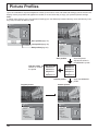
Picture Proles
Up to 16 combinations of picture adjustment values (in the Picture menu and Advanced settings) can be stored in the
display memory as proles and applied as needed, for a convenient way to enjoy your preferred picture settings.
Note:
If setting items (Picture menu and Advanced settings) are set differently between Memory save and Memory load,
they may not reect for Memory load.
Picture
Normalise
Normal
Picture Mode
Contrast
Brightness
Colour
Hue
Sharpness
White balance
Advanced settings
Dynamic
18
0
0
0
3
Normal
Save proles(page 31)
Memory save
Memory load
Memory edit
Picture
Normalise
Load proles(page 32)
Normal
Picture Mode
Contrast
Brightness
Colour
Hue
Sharpness
White balance
Advanced settings
Edit proles(page 33)
Cinema
25
0
0
0
5
Normal
Save proles
Edit the prole
Delete or rename
the prole
Save the picture
adjustment values in
the MEMORY1 prole
MY PICTURE
MEMORY2
MEMORY3
MEMORY4
MEMORY1
MEMORY2
MEMORY3
MEMORY4
MEMORY16
MEMORY16
Load the prole
Original picture
Custom picture
Picture
Normalise
Picture
Normalise
Normal
Picture Mode
Contrast
Brightness
Colour
Hue
Sharpness
White balance
Advanced settings
30
Apply the MEMORY1
prole
Normal
0
0
0
0
0
Normal
Normal
Picture Mode
Contrast
Brightness
Colour
Hue
Sharpness
White balance
Advanced settings
Cinema
25
0
0
0
5
Normal
Picture Proles
Saving proles
Follow these steps to save picture adjustment values as proles.
Note:
When the settings are locked in “Extended life settings”, proles cannot be saved.
1
Specify the picture quality in the Picture menu and
Advanced settings. (see page 25, 26)
2
In the Picture menu, select “Memory save”.
Memory save
Memory load
Memory edit
5
2 access
1 select
3
Enter a name for the prole.
[Entering prole names]
Prole names can be up to 40 characters.
To enter text, select characters in the on-screen
keyboard.
Edit the default prole name in the text box as
desired.
Memory name input
A
N
a
n
0
!
_
Select a prole name for saving the picture adjustment
values.
Memory save
1. [
2. [
3. [
4. [
4
]
]
]
]
MEMORY1
MEMORY2
MEMORY3
MEMORY4
2
set
1
select
B
O
b
o
1
”
`
C
P
c
p
2
#
|
MEMORY1
D E F
Q R S
d e f
q r s
3 4 5
$ % &
~ < >
Ok
1 select
G
T
g
t
6
’
(
H
U
h
u
7
)
I
V
i
v
8
+
[
J
W
j
w
9
–
]
K
X
k
x
L M
Y Z
l m
y z
Space
/ = ?
{
}
,
Cancel
All delete
Delete
2 set
@
.
\
;
ˆ
:
Example: Specifying “MY PICTURE”
“” appears for a prole in which the picture
adjustments have already been saved.
1
Select “Ok”.
All text is deleted.
To delete individual characters, select “Delete”.
Select “All delete”.
MEMORY1
Memory save
Save the adjusted value in ”MEMORY1”
Ok
Cancel
2
1 select
Select “M”.
M
2 set
Repeat this process to enter the next character.
3
Select “Y”.
MY
4
Select “Space”.
MY
6
When you nished entering the prole name, select
“Ok”.
To cancel saving the prole, select “Cancel”.
Memory name input
A
N
a
n
0
!
_
B
O
b
o
1
”
`
C
P
c
p
2
#
|
MY PICTURE
D E F G
Q R S T
d e f g
q r s t
3 4 5 6
$ % & ’
~ < > (
Ok
1 select
H
U
h
u
7
)
I
V
i
v
8
+
[
J
W
j
w
9
–
]
K
X
k
x
L M
Y Z
l m
y z
Space
/ = ?
{
}
,
Cancel
All delete
Delete
2 set
@
.
\
;
ˆ
:
31
Picture Proles
Loading proles
Load proles and apply the picture adjustment values to the display as follows.
Notes:
• Loaded proles are stored in memory according to the selected input terminal. (see page 15)
• When the settings are locked in “Extended life settings”, proles cannot be loaded.
<Loading proles directly from the remote control>
<Loading proles from the Picture menu>
1
In the Picture menu, select “Memory load”.
2 access
Memory save
Memory load
Memory edit
2
1
select
2
set
Select the prole to load.
]
]
]
]
1
Press a button in the range
2
Select “Ok”.
Memory load
Memory load
1. [
2. [
3. [
4. [
To load proles 1–9
–
.
1
select
2
set
Load from ”MEMORY2”
MEMORY1
MEMORY2
MEMORY3
MEMORY4
1
select
Ok
Cancel
To load proles 10–16
Example: To load prole 16
<Loading proles from
1
Press
2
Select the prole to load.
on the remote control>
1
to list the proles.
Press
.
The prole number is displayed in the upper-right
corner of the screen.
16
Memory load
1. [
2. [
3. [
4. [
]
]
]
]
MEMORY1
MEMORY2
MEMORY3
MEMORY4
2
set
1
select
2
Select “Ok”.
Memory load
1
select
2
set
Load from ”MEMORY16”
Ok
PC
When prole is being loaded,
prole name is displayed.
32
16:9
Memory name: MEMORY2
NANODRIFT
Cancel
Picture Proles
Editing proles
Delete or rename proles as follows.
<Deleting proles>
1
2
<Renaming proles>
In the Picture menu, select “Memory edit”.
Memory save
Memory load
Memory edit
1
select
2
Memory delete
Memory name change
1
set
1. [
2. [
3. [
4. [
]
]
]
]
MEMORY1
MEMORY2
MEMORY3
MEMORY4
All delete
2
Memory save
Memory load
Memory edit
Memory delete
Memory name change
3
set
1
select
1. [
2. [
3. [
4. [
4
]
]
]
]
MEMORY1
MEMORY2
MEMORY3
MEMORY4
1
Delete the “MEMORY1” data.
2
A
N
a
n
0
!
_
select
set
Cancel
5
1
select
2
set
1
select
2
set
1
select
1
select
2
set
Enter a name for the prole.
page 31
Entering prole names
Memory name input
Memory delete
access
Select the prole to rename.
Memory name change
2
2
Select “Memory name change”.
Memory edit
Select “Ok”.
Ok
In the Picture menu, select “Memory edit”.
select
Select the prole to delete.
To delete all proles, select “All delete”.
Memory delete
4
access
Select “Memory delete”.
Memory edit
3
2
1
B
O
b
o
1
”
`
C
P
c
p
2
#
|
EMORY1
M
D E F
Q R S
d e f
q r s
3 4 5
$ % &
~ < >
Ok
G
T
g
t
6
’
(
H
U
h
u
7
)
I
V
i
v
8
+
[
J
W
j
w
9
–
]
K
X
k
x
L M
Y Z
l m
y z
Space
/ = ?
{
}
,
Cancel
All delete
Delete
@
.
\
;
ˆ
:
When you nished entering the prole name, select
“Ok”.
To cancel renaming the prole, select “Cancel”.
Ok
Cancel
1
select
2
set
33
Setup menu
1
Press to display the Setup menu.
Press to select the menu to adjust.
2
Press to adjust the menu.
3
Press to exit from menu.
Setup
3D Settings
Signal
Screensaver
Extended life settings
Input label
YUV/RGB-in select
Power save
PC Power management
Auto power off
OSD Language
RGB
Off
Off
Off
English (UK)
YUV / RGB-in select
This menu is displayed when DVI-D Terminal Board (TY-FB11DD) is installed to the unit.
RGB
YUV
Select to match the signals from the source connected to the DVI input terminals.
YUV signals
“YUV”
RGB signals
“RGB”
Power save
Off
On
When this function is turned On, luminous level of the Plasma Display is suppressed, so power consumption is
reduced.
PC Power management
Off
On
When this function is set to On, it operates under the following conditions to turn the power on or off automatically.
When no pictures (HD/VD sync signals) are detected for 30 or so seconds during PC signal input:
Power is turned off (standby); the power indicator lights up orange.
When pictures (HD/VD sync signals) are subsequently detected:
Power is turned on; the power indicator lights up green.
Notes:
• This function operates only during PC signal input.
• This function is effective when “Sync” is set to “Auto”. (see page 36)
Auto power off
Off
On
Equipment power supply is turned Off when there is no signal.
When this is set to On, the power supply of the unit goes Off 10 minutes after the input signals stop.
34
Setup menu
OSD Language
Select your preferred language.
Selectable languages
English(UK)
Deutsch
Français
Italiano
Español
ENGLISH(US)
.......(Chinese)
.......(Japanese)
.......(Russian)
3D Settings
If the 3D images are not displayed correctly or seem unusual, please adjust and setup the 3D settings.
Setup
3D Settings
Signal
Screensaver
Extended life settings
Input label
Power save
Off
PC Power management
Off
Auto power off
Off
OSD Language
English (UK)
Select the item and set.
2
access
1
select
3D Settings
3D Picture Display
3D Picture Format
3D Picture Sequence
Safety Precautions
3D
Auto
Off
2
change
1
select
• 3D Picture Display
3D
2D
3D: Use of 3D Eyewear. You can see 3D images for 3D image signal and 2D images for 2D image signal.
2D: No use of 3D Eyewear. You can see 2D images instead of 3D images.
When set to “3D”, “3D” is displayed during 3D images.
PC
3D
16:9
NANODRIFT
• 3D Picture Format
3D images method is set.
Auto: 3D images are automatically displayed according to the signal.
Side by Side/Top and Bottom: One of the formats of the 3D standard. Select these formats as necessary.
Native: Displays the input signal as it is. Use to identify the format type of the input signal.
• 3D Picture Sequence
On
Off
This function calibrates the timing to switch the right and left images as well as the timing to switch the shutter of
right and left 3D Eyewear.
Select “On” if you feel that the sense of depth is unusual.
• Safety Precautions
Displays the precautions for viewing 3D images.
35
Setup menu
SIGNAL menu
Note:
“Signal” setup menu displays a different setting condition for each input signal.
Setup
3D Settings
Signal
Screensaver
Extended life settings
Input label
Power save
Off
PC Power management
Off
Auto power off
Off
OSD Language
English (UK)
Select the item and set.
2
access
1
select
For RGB
2
change
1
select
[ RGB ]
Signal
Sync
XGA Mode
H-Freq.
V-Freq.
Signal Format
Auto
Auto
63.98 kHz
60.02 Hz
1280×1024/60
Input signal display
Displays the frequency and the type of the current
input signal.
This display is valid only for RGB / PC and Digital
input signal.
Display range:
Horizontal 15 - 110 kHz
Vertical 48 - 120 Hz
The dot clock frequency is displayed during digital
signal input.
For Digital
[ Digital ]
Signal
24p SMOOTH FILM
3D 24p Film Display
HDMI Range
H-Freq.
V-Freq.
Dot Clock Freq.
Signal Format
63.98
Off
60Hz
Auto
kHz
60.02 Hz
108.0 MHz
1280×1024/60
• XGA Mode
This menu is displayed when the input signal is analog (PC). This unit supports three types of XGA signals with 60Hz vertical
frequency having different aspect ratios and sampling rates (1,024 × 768 @ 60Hz, 1,280 × 768 @ 60Hz and 1,366 × 768 @ 60Hz).
Auto
1024×768
1280×768
1366×768
Auto: Automatically selected from 1024×768/1280×768/1366×768.
Switch the setting to suit the input signal for better display depends on the angle of view or display resolution condition.
Note:
After making this setting, be sure to make each adjustment (such as “Auto Setup”) on the “Pos. /Size” menu as
necessary. (see page 22)
• Sync
This function operates only during input from PC IN terminal.
Setting RGB sync signal
Conrm that the input is set to RGB input (this setting is valid only for RGB input signal).
Auto: The H and V sync or synchronized signal is automatically selected. If both input, it is selected the H and V sync.
on G: Uses a synchronized signal on the Video G signal, which is input from the G connector.
VBS: Uses a synchronized signal of Composite Sync input, which is input from the HD connector.
• SDI Through
Set the active through function of the Dual Link HD-SDI Terminal Board (TY-FB11DHD).
On
Off
On: Enables active through.
Off: Disables active through.
Note:
Settings can only be performed for this menu when a slot mounted with a Dual Link HD-SDI Terminal Board
(TY-FB11DHD) is selected.
• FRAME CREATION
Displays reducing screen icker image for 50Hz/25Hz signal input.
On
Off
Note:
This function activates only for 50Hz/25Hz signal input with 2D images.
36
Setup menu
• 24p SMOOTH FILM
• 3D 24p Film Display
During 2D or 3D viewing, images captured at 24
frames per second are provided in a smooth manner.
Off
On
Note:
This function can be set only for 24p signal input with 2D
or 3D images
For 3D images, images captured at 24 frames per second are set.
60Hz
48Hz
60Hz: Increases the number of frames to reproduce
more natural movement images.
48Hz: Reproduces images like lm-specic.
Note:
This function can be set only for 24p signal input with 3D images.
• HDMI Range
Switches the dynamic range according to the input signal from HDMI 1 and HDMI 2 terminals.
Full(0-255)
Auto
Video(16-235)
Video(16-235): If the input signal is the video range, Example: HDMI terminal output for DVD player
Full(0-255): If the input signal is full range, Example: HDMI terminal output for personal computer
Auto: Switches the dynamic range automatically between “Video(16-235)” and “Full(0-255)” according to the input signal.
Note:
This function can be set only for HDMI 1 and HDMI 2 terminal input.
• SDI Signal Format
Enabled only when the signal is input to the 4K SDI IN terminal.
Selects the format of the input signal for the 4K SDI IN terminal.
For 3,840/30p or 3,840/24p signal input:
YCbCr(4:4:4) 10bit
RGB(4:4:4) 10bit
YCbCr(4:2:2) 12bit
Auto
RGB(4:4:4) 12bit
For 4,096/24p signal input:
RGB(4:4:4) 12bit
XYZ(4:4:4) 12bit
Auto
Auto: Automatically selects the signal format according to the input signal.
YCbCr(4:4:4) 12bit
Screensaver
Do not display a still picture, especially in 4:3 mode, for any length of time.
If the display must remain on, a Screensaver should be used.
Setup
3D Settings
Signal
Screensaver
Extended life settings
Input label
Power save
Off
PC Power management
Off
Auto power off
Off
OSD Language
English (UK)
2
access
1
select
Screensaver
Start
Function
Negative image
1 Function selection
Screensaver
Start
Function
2
change
1
select
Negative image
White screen
Scrolling bar only
Overlay scrolling bar
Negative image
Negative image : Negative image will be displayed on the screen.
Scrolling bar only : A white bar will scroll from left to right. The image won't be displayed.
Overlay scrolling bar : The brightness of the image will be decreased and a white bar will scroll on it.
White screen : The whole screen will be white.
Note:
When the input signal is a 4k2k signal, only “Scrolling bar only” and “White screen” can be selected.
setting
2 Start
Select “Start”.
2
set
1
select
Screensaver
Start
Function
Negative image
The menu screen will disappear and the
SCREENSAVER will be activated. To stop the
Screensaver under On, press any button.
Note: When the display is turned off, the
Scrensaver will be deactivated.
37
Setup menu
Extended life settings
The following settings are setup to reduce image retention:
Extended life settings
Setup
3D Settings
Signal
Screensaver
Extended life settings
Input label
Power save
Off
PC Power management
Off
Auto power off
Off
OSD Language
English (UK)
2
access
1
select
Express settings
Custom settings
Reset
Set to the recommended value
Set individually
Reset to the factory settings
Extended life settings
Recommended settings
Picture Mode
Contrast
Side panel
NANODRIFT Saver
Peak limit
Lock settings
Apply to current input
Apply to all inputs
Dynamic
30
High
Mid
Off
unlock
Image Retention Reduction
Menu
Image Retention Reduction Menu
“Extended life settings” enables you to set the following 5 menus (Image Retention Reduction Menu) as recommended
values or set them individually.
Picture Mode
Contrast
“Picture Mode” and “Contrast” are same as “Picture” menu items (see page 25). The settings of this menu will be
reected to the “Picture” menu.
Side panel
Do not display a picture in 4:3 mode for an extended period,
as this can cause an image retention to remain on the side
panels on either side of the display eld.
To reduce the risk of such an image retention, illuminate
the side panels.
This function may be applicable to the non-picture area.
Off:
Low:
Mid:
High:
side panel
4:3 Screen
Display
image
retention
Darken both ends.
Make it dark gray.
Make it gray.
Make it light gray.
Notes:
• To reduce the occurrence of image retention, set the Side panel to High.
• The side panel may ash (alternate black/white) depending on the picture being shown on the screen. Using Cinema
mode will reduce such ashing.
38
Setup menu
NANODRIFT Saver
Moves the display position of the screen slightly to reduce image retention on the display panel.
Low–High: NANODRIFT Saver operates. The display position of the screen moves at set time intervals. You can set
the screen movement range. Some of the screen may appear to be missing as a result of this operation.
If you change the value, a mask is displayed in the range where the picture is missing as a result of
position movement.
Note:
A mask is not displayed when the input signal is a 4k2k signal.
When “NANODRIFT” Image Retention Reduction is
operating, “NANODRIFT” is displayed.
PC
16:9
NANODRIFT
Peak limit
On: Suppresses image contrast (peak brightness).
Note: When a still picture is viewed for an extended time, the screen may become slightly darker. (see page 45)
Express settings
Set the “Image Retention Reduction” menu to the recommended settings.
All menus will be locked.
Picture Mode: Normal
Contrast: Recommended setting for each model
Side panel: High
NANODRIFT Saver: Mid
Peak limit: On
1 Select “Express settings”.
Extended life settings
2 access
Express settings
Custom settings
Reset
1 select
2 Select the input to apply the settings.
Extended life settings
2 set
Apply to current input
Apply to all inputs
1 select
3 Select “Yes”.
Extended life settings
Apply to current input
Yes
No
1 select
2 set
39
Setup menu
Custom settings
Set the individual “Image Retention Reduction” menu.
1 Select “Custom settings”.
Extended life settings
Express settings
Custom settings
Reset
2
access
1
select
set each menu to the recommended setting:
2 To
Select “Recommended settings”.
2
Extended life settings
set
Recommended settings
Picture Mode
Contrast
Side panel
NANODRIFT Saver
Peak limit
Lock settings
Apply to current input
Apply to all inputs
When a menu is locked, it is grayed out and cannot
be set.
“Picture Mode” and “Contrast” will no longer be able
to set in the “Picture” menu, and they are labeled
with icon to indicate their locked status. Also,
“Normalise”, “Memory save” and “Memory load”
are not available.
Picture
Normalise
Dynamic
30
High
Mid
Off
Unlock
1
select
Each menu will be set as same
as the “Express settings”.
Normal
Picture Mode
Contrast
Brightness
Colour
Hue
Sharpness
White balance
Advanced settings
Dynamic
30
0
0
0
5
Normal
Memory save
Memory load
Memory edit
Extended life settings
3
Set each menu.
Extended life settings
Recommended settings
Picture Mode
Contrast
Side panel
NANODRIFT Saver
Peak limit
Lock settings
Apply to current input
Apply to all inputs
adjust
1 select
2
Dynamic
30
High
Mid
Off
Unlock
Extended life settings
2
set
1
select
1
select
2
set
1
select
2
set
Recommended settings
Picture Mode
Contrast
Side panel
NANODRIFT Saver
Peak limit
Lock settings
Apply to current input
Apply to all inputs
lock each menu setting:
4 To
Set the “Lock settings” to “Lock”.
Dynamic
30
High
Mid
Off
Lock
6 Select “Yes”.
Extended life settings
Extended life settings
adjust
1 select
2
Recommended settings
Picture Mode
Contrast
Side panel
NANODRIFT Saver
Peak limit
Lock settings
Apply to current input
Apply to all inputs
5 Select the input to apply the settings.
Dynamic
30
High
Mid
Off
Lock
Apply to current input
Yes
No
Reset
Reset the “Image Retention Reduction” menu to the factory settings. Each menu will be unlocked.
1 Select “Reset”.
Extended life settings
Express settings
Custom settings
Reset
2 Select the input to reset the settings.
Extended life settings
Reset current input
Reset all inputs
40
2
access
3 Select “Yes”.
Extended life settings
Reset current input
1
select
2
set
1
select
Yes
No
Setup menu
Customizing the Input labels
This function can change the label of the Input signal to be displayed. (see page 15)
Select an input terminal and set.
Setup
3D Settings
Signal
Screensaver
Extended life settings
Input label
Power save
Off
PC Power management
Off
Auto power off
Off
OSD Language
English (UK)
2
access
1
select
Input label
HDMI1
HDMI2
SLOT INPUT
4K-SDI
4K-DVI
PC
HDMI1
HDMI2
SLOT INPUT
4K-SDI
4K-DVI
PC
2
change
1
select
Note:
The setting items are the same as the input terminal list of
“Selecting the input signal” (page 15).
The input label changes as follows each time the or button is pressed.
Original
DVD1
(Skip)
DVD2
STB
DVD3
VCR
DVD4
CATV
Blu-ray1
Blu-ray4
Blu-ray2
Blu-ray3
(Skip) : The INPUT button press will skip its input.
41
Options Adjustments
Setup
1
Press to display the Setup menu.
2
Press to select “OSD Language”.
3D Settings
Signal
Screensaver
Extended life settings
Input label
Power save
Off
PC Power management
Off
Auto power off
Off
OSD Language
English (UK)
Press for more than 3 seconds.
Press to select “Options”.
3
Options
Shipping
Press to display the Options menu.
Press to select your preferred menu.
4
Options
5
Onscreen display
Initial input
Input lock
42
Initial input
Input lock
Button lock
Remocon User level
Off-timer function
Aspect Mode
Auto Setup
Studio mode
Function button assign 1
Function button assign 2
Function button assign 3
Function button assign 4
H-Position
V-Position
3D Safety Precautions
Press to exit from Options menu.
Item
On
Onscreen display
Press to adjust the menu.
Adjustments
On: Displays all the following on screen.
• Power on display
• Input signal switch display
• No signal display
• Mute and the remaining time of off-timer after
Off: Hides all the items above from view.
was pressed.
Adjusts the input signal when the unit is turned on.
HDMI
HDMI2
SLOT INPUT*
4K-SDI
4K-DVI
PC
Off
* “SLOT INPUT” is displayed when an optional Terminal Board is installed.
Notes:
• Only the adjusted signal is displayed. (see page 15)
• This menu is available only when “Input lock” is “Off”.
Locks the input switch operation.
Off
HDMI
HDMI2
SLOT INPUT*
4K-SDI
4K-DVI
PC
* “SLOT INPUT” is displayed when an optional Terminal Board is installed.
Notes:
• Only the adjusted signal is displayed (see page 15).
• Input switch can be used when this is set to “Off”.
Off
Off
Off
Off
Enable
Mode1
Manual
Off
3D settings
Scrolling bar
Test patterns
Blue only
0
0
On
Options Adjustments
Item
Adjustments
MENU&ENTER
On
Off
Off: All the buttons at the right side of the main unit can be used.
Button lock
MENU&ENTER:
ENTER/ buttons on right side of main unit.
MENU and
Locks
On: Locks all the button on right side of main unit.
Sets Button lock with the unit buttons in the following procedure.
INPUT four timesPress
ENTER/
Off: Press
four timesPress
four timesPress
INPUT four timesPress
ENTER/ four timesPress
ENTER/
MENU&ENTER: Press
four timesPress
ENTER/ four timesPress
ENTER/
On: Press
four timesPress
four timesPress
User1
User2
User3
Off
Off: You can use all of the buttons on the remote control.
Remocon User level
User1: You can only use
,
,
,
,
,
,
buttons on the remote control.
button on the remote control.
User2: You can only use
User3: Locks all the buttons on remote control.
Off-timer function
Aspect Mode
Auto Setup
Enable: Enables the “Off-timer function”.
Disable: Disables the “Off-timer function”.
Note: When “Disable” is set, the Off-timer is cancelled.
Select the aspect switching pattern on pressing
from the 3 modes.
Mode1: Aspect mode suitable for regions such as Europe and China (PAL/SECAM system)
Mode2: Aspect mode suitable for regions such as North America and Japan (NTSC system)
All Aspect: Aspect mode for all aspect options
Sets the operational mode of the automatic position adjustment in the Pos./Size menu.
is pressed on the remote control or automatic
Manual: Automatic position adjustment starts when
position adjustment is executed from the Pos./Size menu.
Auto: Other than remote control or menu operation, automatic position adjustment starts:
When the display power is turned ON.
When the input signal is switched.
For switching functions in setting menus used for television studio applications.
Studio mode: On
White balance
Studio mode
Studio Gain
Under scan
Function button
assign 1
Function button
assign 2
Function button
assign 3
Function button
assign 4
Studio mode: Off
“Studio” can be selected.
“Studio” not available.
Cannot be specied
Can be switched On and Off. (set to “Off” and cannot be changed).
Cannot be specied
Can be switched On and Off. (set to “Off” and cannot be changed).
Set the function to operate when the FUNCTION button 1 to 4 on the remote control is pressed.
3D settings: The “3D Settings” menu is displayed.
Scrolling bar: The screen saver activates, and after 15 minutes, the display power shuts down
(standby).
Test patterns: The test pattern is displayed by switching among seven patterns.
Blue only: The screen displays only blue color for image adjustment.
Signal: The “Signal” menu is displayed.
When the input signal is a 4k2k signal, adjust the horizontal position.
H-Position
The four split screens respectively
move in the horizontal direction.
When the input signal is a 4k2k signal, adjust the vertical position.
V-Position
The four split screens respectively
move in the vertical direction.
43
Options Adjustments
Item
Adjustments
3D Safety Precautions show/hide is set during power ON.
On: 3D Safety Precaution is shown every time when the power is ON.
Off: 3D Safety Precaution is not shown when the power is ON.
When the setting changes from “On” to “Off”, the conrmation screen is displayed as below.
Pressing “YES” switches the setting.
3D Safety Precautions
3D Safety Precautions
If Off is selected, the 3D safety precautions
will not be displayed when power is turned on.
Change Setting?
YES
NO
Normalization
When both main unit buttons and remote control are disabled due to the “Button lock” or “Remocon User level”
adjustments, set all the values “Off” so that all the buttons are enabled again.
button on main unit together with
button on the remote control and hold for more than 5 seconds.
Press the
The “Shipping” menu is displayed and the lock is released when it disappears.
Using FUNCTION button
Pressing the FUNCTION button activates one of the following ve functions. The settings of
functions are performed with the “Function button assign 1” to “Function button assign 4” on
the Options menu. (see page 43)
3D Settings / Signal
The menu screen is displayed.
(Example: 3D Settings)
3D Settings
3D Picture Display
3D Picture Format
3D Picture Sequence
Safety Precautions
3D
Auto
Off
Pressing the FUNCTION button clears the menu.
Scrolling bar / Test patterns / Blue only
Conrmation screen (Example: Scrolling bar)
Press to
select
“Yes”.
Function 1
The operation
starts.
Scrolling bar
Yes
Press.
No
Scrolling bar
Test patterns
Activates the “Scrolling bar only” screensaver. After
15 minutes, the display enters standby mode.
Each time you press , a different test pattern is
displayed (seven in all).
Color Bars
To exit this mode, press any button.
Black
1% window
Red
Green
Frame
(2 lines × 2 dots)
Blue
Blue only
The screen displays only blue color for image
adjustment.
To exit this mode, press FUNCTION button.
To exit this mode, press any button other than
.
Note:
“PC Power management” and “Auto power off” are deactivated during “Scrolling bar” or “Test patterns” operation.
(see page 34)
44
Troubleshooting
Before you call for service, determine the symptoms and make a few simple checks as shown below.
Symptoms
Checks
Electrical Appliances
Cars / Motorcycles
Fluorescent light
The breaker is turned off.
Not switched on
Picture and Brightness setting
Interference
No Picture
(Check by pressing
button on the remote control.)
If a signal with a non-applicable colour system format, or frequency is input, only
the input terminal indication is displayed.
Colour controls set at minimum level
(see page 25, 26)
No Colour
No remote control operations can be performed.
A cracking sound is sometimes heard from the unit.
The top or bottom of the picture on the screen is cut
off when I use the zoom function.
Areas at the top and bottom of the screen where
the image is missing appear when I use the zoom
function.
I can hear sounds coming from inside the unit.
Check whether the batteries have discharged completely and, if they have not,
whether they were inserted properly.
Check whether the remote control sensor is exposed to an outdoor light or a
strong uorescent light.
Check whether the remote control designed specically for use with the unit is
being used. (The unit cannot be operated by any other remote control.)
If there is nothing wrong with the picture, this is the sound of the cabinet undergoing
very slight contractions in response to changes in the room temperature. There are
no adverse effects on the performance or other aspects.
Adjust the position of the picture on the screen.
When using a video software program (such as a cinema size program) with a
screen wider than one in the 16:9 mode, blank areas separate from the images
are formed at the top and bottom of the screen.
When the power is turned on, a sound of the display panel being driven may be
heard: This is normal and not indicative of malfunctioning.
Even when the temperature of parts of the front, top and rear panels has risen, these
Parts of the unit become hot.
temperature rises will not pose any problems in terms of performance or quality.
Power automatically turns off unexpectedly.
Check the settings of “PC Power management” and “Auto power off” in the Setup
menu. Any of them may be set to “On”. (see page 34)
Power indicator is blinking in red.
There is possibility of malfunction. Please contact an Authorized Service
Center.
This Plasma Display uses special image processing. Hence a slight time lag may occur between image, depending on the type of input
signal. However, this is not a malfunction.
Plasma Display panel
Symptoms
The screen darkens slightly
when bright pictures with minimal
movements are shown.
It takes a while for the picture
to appear.
The edges of the images
icker.
The brightness on both sides of
images in the 4:3 mode changes.
Some parts of the screen do
not light up.
Image retention appears
Whirring sounds can be heard
from the display unit.
Check
The screen will darken slightly when photos, still images of a computer or other pictures with minimal
movements are shown for an extended period. This is done to reduce image retention on the screen
and the shortening of the screen’s service life: It is normal and not indicative of malfunctioning.
The unit digitally processes the various signals in order to reproduce esthetically pleasing images. As
such, it sometimes takes a few moments for the picture to appear when the power has been turned
on, when the input has been switched or when the images for the main picture and sub picture on
the two screens are swapped.
Due to the characteristics of the system used to drive the panel, the edges may appear to icker in
the fast-moving parts of the images: This is normal and not indicative of malfunctioning.
When viewing the side panels at the “High” or “Mid” setting, the brightness on both sides may change
depending on the kind of program shown: This is normal and not indicative of malfunctioning.
The plasma display panel is manufactured using an extremely high level of precision technology,
however, sometimes some parts of the screen may be missing picture elements or have luminous
spots. This is not a malfunction.
Do not allow a still picture to be displayed for an extended period, as this can cause a permanent image retention to
remain on the Plasma Display.
Examples of still pictures include logos, video games, computer images, teletext and images displayed in 4:3 mode.
Note:
The permanent image retention on the Plasma Display resulting from xed image use is not an
operating defect and as such is not covered by the Warranty.
This product is not designed to display xed images for extended periods of time.
The display unit is tted with a cooling fan to dissipate heat generated during normal use. The whirring
sound is caused by rotation of the fan and is not a malfunction.
45
List of Aspect Modes
Aspect Mode
Mode 1
All Aspect Factory Mode 2
setting
16:9
14:9
16:9
14:9
16:9
–
The display of the pictures lls the screen.
In the case of SD signals, pictures with a 4:3 aspect
ratio are enlarged horizontally, and displayed. This
mode is suited to displaying anamorphic pictures with
a 16:9 aspect ratio.
Just
Pictures with a 4:3 aspect ratio are enlarged horizontally
so that the picture distortion is minimized. The display of
the areas around the left and right edges of the screen
is slightly elongated.
Just
The pictures with a 4:3 aspect ratio among the 16:9 aspect
ratio signals are enlarged horizontally so that the picture
distortion is minimized. The left and right edges of the
pictures are cut off. The display of the areas around the
left and right edges of the screen is slightly elongated.
4:3
4:3
Description
–
Just1
Just2
Enlarged screen
Letterbox pictures with a 14:9 aspect ratio are enlarged
vertically and horizontally so that their display lls the
screen vertically and is slightly smaller than the screen
horizontally. The top and bottom edges of the pictures
are cut off. Side panels are displayed at the left and right
edges of the screen.
Just
Just
Picture
4:3
Pictures with a 4:3 aspect ratio are displayed with their
original aspect ratio. Side panels are displayed at the
left and right edges of the screen.
4:3 (1)
4:3 (2)
–
4:3
The pictures with a 4:3 aspect ratio among the 16:9
aspect ratio signals are displayed with their original
aspect ratio. The left and right edges of the pictures are
masked with side panels.
4:3 Full
4:3
Full
4:3
Full
The pictures with a 4:3 aspect ratio among the 16:9
aspect ratio signals are enlarged horizontally so that
their display lls the screen. The left and right edges of
the pictures are cut off.
Zoom
Letterbox pictures with a 16:9 aspect ratio are enlarged
vertically and horizontally so that their display lls the
screen. The top and bottom edges of the pictures are
cut off.
Zoom
The letterbox pictures with a 2.35:1 aspect ratio among
the 16:9 aspect ratio signals are enlarged vertically and
horizontally so that their display lls the screen. The top
and bottom edges as well as the left and right edges of
the pictures are cut off.
–
Letterbox pictures with a 2.35:1 aspect ratio are enlarged
vertically and horizontally so that their display lls the
screen vertically and is slightly larger than the screen
horizontally. The top and bottom edges as well as the
left and right edges of the pictures are cut off.
Zoom
Zoom1
Zoom1
Zoom2
Zoom3
46
Zoom2
Zoom3
Applicable Input Signals
*Mark: Applicable input signal
Signal name
1
2
3
4
5
6
7
8
9
10
11
12
13
14
15
16
17
18
19
20
21
22
23
24
25
26
27
28
29
30
31
32
33
34
35
36
37
38
39
40
41
42
43
44
45
46
47
48
49
50
51
52
53
54
55
525 (480) / 60i
525 (480) / 60p
625 (575) / 50i
625 (576) / 50i
625 (575) / 50p
625 (576) / 50p
750 (720) / 60p
750 (720) / 50p
1,125 (1,080) / 60i
1,125 (1,080) / 50i
1,125 (1,080) / 60p
1,125 (1,080) / 50p
1,125 (1,080) / 30p
1,125 (1,080) / 25p
1,125 (1,080) / 24p
1,125 (1,080) / 24sF
1,250 (1,080) / 50i
2,048 × 1,080 / 24p 6
2,048 × 1,080 / 24sF 6
2,048 × 1,080 / 60p
640 × 400 @ 70Hz
640 × 480 @ 60Hz
640 × 480 @ 72Hz
640 × 480 @ 75Hz
640 × 480 @ 85Hz
800 × 600 @ 56Hz
800 × 600 @ 60Hz
800 × 600 @ 72Hz
800 × 600 @ 75Hz
800 × 600 @ 85Hz
852 × 480 @ 60Hz
1,024 × 768 @ 50Hz
1,024 × 768 @ 60Hz
1,024 × 768 @ 70Hz
1,024 × 768 @ 75Hz
1,024 × 768 @ 85Hz
1,066 × 600 @ 60Hz
1,152 × 864 @ 60Hz
1,152 × 864 @ 75Hz
1,280 × 768 @ 60Hz
1,280 × 960 @ 60Hz
1,280 × 960 @ 85Hz
1,280 × 1,024 @ 60Hz
1,280 × 1,024 @ 75Hz
1,280 × 1,024 @ 85Hz
1,366 × 768 @ 50Hz
1,366 × 768 @ 60Hz
1,400 × 1,050 @ 60Hz
1,600 × 1,200 @ 60Hz
1,600 × 1,200 @ 65Hz
1,920 × 1,080 @ 60Hz
1,920 × 1,200 @ 60Hz
Macintosh13” (640 × 480)
Macintosh16” (832 × 624)
Macintosh21” (1,152 × 870)
Horizontal
frequency
(kHz)
15.73
31.47
15.63
15.63
31.25
31.25
45.00
37.50
33.75
28.13
67.50
56.25
33.75
28.13
27.00
27.00
31.25
27.00
27.00
67.50
31.46
31.47
37.86
37.50
43.27
35.16
37.88
48.08
46.88
53.67
31.47
39.55
48.36
56.48
60.02
68.68
37.64
53.70
67.50
47.70
60.00
85.94
63.98
79.98
91.15
39.55
48.36
65.22
75.00
81.25
67.50
74.04
35.00
49.72
68.68
DVI-D
Vertical
SDI IN
IN
frequency
4k2k
4k2k
(Hz)
59.94
59.94
50.00
50.00
50.00
50.00
60.00
50.00
60.00
50.00
* 7
60.00
* 7
50.00
* 7
30.00
* 7
25.00
24.00
* 7
48.00
50.00
24.00
* 7
48.00
60.00
* 7
* 7
70.07
59.94
72.81
75.00
85.01
56.25
60.32
72.19
75.00
85.06
59.94
50.00
60.00
70.07
75.03
85.00
59.94
60.00
75.00
60.00
60.00
85.00
60.02
75.03
85.02
50.00
60.00
60.00
60.00
65.00
60.00
59.95
66.67
74.54
75.06
PC IN
(Dot clock (MHz))
*
*
(13.5)
5
(13.5)
*
(27.0)
HDMI
1/2
*
*
SLOT
DVI-D IN
(Dot clock (MHz))
*
(27.0)
*
*
*
*
*
*
*
*
*
*
*
(27.0)
(74.25)
(74.25)
(74.25)
(74.25)
(148.5)
(148.5)
(74.25)
(74.25)
(74.25)
*
*
(25.18)
*
*
(40.0)
*
*
*
*
(34.24)
(51.89)
(65.0)
*
*
(53.0)
(81.62)
*
(108.0)
*
*
*
*
(69.92)
(87.44)
(122.61)
(162.0)
*
*
(148.5)
(154.0)
*
*
*
*
*
*
*
*
*
*
*
*
(74.25)
(74.25)
(74.25) 1
(74.25) 1
(148.5) 1
(148.5) 1
(74.25) 1
(74.25) 1
(74.25) 1
(74.25) 2
(74.25) 3
*
*
*
*
*
*
*
*
*
*
*
(25.17)
(25.18)
(31.5)
(31.5)
(36.0)
(36.0)
(40.0)
(50.0)
(49.5)
(56.25)
(33.54)
*
*
*
*
*
(65.0)
(75.0)
(78.75)
(94.5)
(53.0)
*
*
*
*
*
*
*
(108.0)
(80.14)
(108.0)
(148.5)
(108.0)
(135.0)
(157.5)
*
(86.71)
*
*
*
(162.0)
(175.5)
(148.5)
*
*
*
(30.24)
(57.28)
(100.0)
5
*
*
*
*
*
*
*
5
*
4
1: Based on SMPTE 274M standard. 2: Based on SMPTE RP211 standard.
3: Based on SMPTE 295M standard. 4: The input signal is recognized as 1,125 (1,080) / 60p.
5: When inputted 525p signal to the PC IN terminal, it is recognized as VGA 60Hz signal.
6: Based on SMPTE 292M and 372M standards. These signals can be received when the Dual Link HD-SDI Terminal
Board (TY-FB11DHD) is installed.
7: For 1 system
Note: Signals without above specication may not be displayed properly.
47
Shipping condition
This function allows you to reset the unit to the factory setting.
1
2
Setup
Press to display the Setup menu.
Press to select “OSD Language”.
Press for more than 3 seconds.
3
Press to select “Shipping”.
3D Settings
Signal
Screensaver
Extended life settings
Input label
Power save
Off
PC Power management
Off
Auto power off
Off
OSD Language
English (UK)
Options
Shipping
Press to display the Shipping menu.
4
Press to select “YES”.
Press to conrm.
[from the unit]
1 Press the MENU button till the Setup menu is displayed.
or
button to select “OSD Language”.
2 Press the
3 Press and hold the ENTER button till the Shipping menu is displayed.
or
button to select “YES”.
4 Press the
5 Press the ENTER button and wait for 10 sec.
48
Shipping
YES
NO
Specications
Power Source
Power Consumption
Power on
Stand-by condition
Power off condition
Plasma Display panel
Screen size
(No.of pixels)
Operating condition
Temperature
Humidity
Applicable signals
Scanning format
PC signals
Connection terminals
AV IN
HDMI 1/2
SDI IN*1
DVI-D IN*1
PC IN
SERIAL
3D SHUTTER OUT*2
SLOT
DVI-D IN
Dimensions (W × H × D)
Mass (weight)
TH-152UX1
200 - 240 V AC, 50/60 Hz
3700 W
0.5 W
0.3 W
Drive method : AC type
152-inch, 17:9 aspect ratio
134.4” (W) × 70.9” (H) × 152.0” (diagonal) /
3,416 mm (W) × 1,801 mm (H) × 3,862 mm (diagonal)
8,847,360 (4,096 (W) ×2,160 (H))
[4,096 × 2,160 × 3 dots]
32°F - 95°F / 0 °C - 35 °C
20 % - 80 %
525 (480) / 60i · 60p, 625 (575) / 50i · 50p, 750 (720) / 60p · 50p, 1125 (1080) / 60i · 60p · 50i ·
50p · 24p · 25p · 30p · 24sF, 1250 (1080) / 50i
VGA, SVGA, XGA, SXGA
UXGA ···· (compressed)
Horizontal scanning frequency 15 - 110 kHz
Vertical scanning frequency 48 - 120 Hz
TYPE A Connector × 2
HDMI (Version 1.4 with 3D)
BNC
0.8 Vp-p (75 )
HD-SDI (Dual Link) × 4, 4K signal input
DVI-D (Single Link) 24 Pin × 4, 4K signal input Compliance with DVI Revision 1.0
High-Density Mini D-sub 15 Pin
G with sync 1.0 Vp-p (75 )
G without sync 0.7 Vp-p (75 )
B: 0.7 Vp-p (75 )
R: 0.7 Vp-p (75 )
HD/VD: 1.0 - 5.0 Vp-p (high impedance)
with picture 1.0 Vp-p (high impedance)
VBS (use HD port)
without picture 0.3 Vp-p (high impedance)
External Control Terminal
D-sub 9 Pin
RS-232C compatible
M3 jack × 1, for 3D active shutter eyewear
DVI-D 24 Pin
Compliance with DVI Revision 1.0
Content Protection
Compatible with HDCP 1.1
Audio Input is not available
141.8” × 78.0” × 5.8”*3 / 3,600 mm × 1,980 mm × 147 mm*3
approx. 1,272.1 lbs / 577 kg net
*1 4 inputs is set and only for one 4k2k signal. You can not input 4 different signal to each inputs.
*2 An optional 3D IR TRANSMITTER is required for viewing 3D images.
*3 10.3” / 260 mm when including protruding portion of terminals
Notes:
• Design and specications are subject to change without notice. Mass and dimensions shown are approximate.
• This equipment complies with the EMC standards listed below.
EN55022, EN55024, EN61000-3-11, EN61000-3-12.
49
Information for Users on Collection and Disposal of Old Equipment and used Batteries
These symbols on the products, packaging, and/or accompanying documents mean that used
electrical and electronic products and batteries should not be mixed with general household waste.
For proper treatment, recovery and recycling of old products and used batteries, please take them to
applicable collection points, in accordance with your national legislation and the Directives
2002/96/EC and 2006/66/EC.
By disposing of these products and batteries correctly, you will help to save valuable resources and
prevent any potential negative effects on human health and the environment which could otherwise
arise from inappropriate waste handling.
For more information about collection and recycling of old products and batteries, please contact your
local municipality, your waste disposal service or the point of sale where you purchased the items.
Penalties may be applicable for incorrect disposal of this waste, in accordance with national
legislation.
For business users in the European Union
If you wish to discard electrical and electronic equipment, please contact your dealer or supplier for
further information.
[Information on Disposal in other Countries outside the European Union]
These symbols are only valid in the European Union. If you wish to discard these items, please
contact your local authorities or dealer and ask for the correct method of disposal.
Note for the battery symbol (bottom two symbol examples):
This symbol might be used in combination with a chemical symbol. In this case it complies with the
requirement set by the Directive for the chemical involved.
Customer’s Record
The model number and serial number of this product can be found on its rear panel. You should note this serial
number in the space provided below and retain this book, plus your purchase receipt, as a permanent record of your
purchase to aid in identication in the event of theft or loss, and for Warranty Service purposes.
Model Number
Serial Number
Pursuant to the directive 2004/108/EC, article 9(2)
Panasonic Testing Centre
Panasonic Service Europe, a division of Panasonic Marketing Europe GmbH
Winsbergring 15, 22525 Hamburg, F.R. Germany
Web Site : http://panasonic.net
¤ Panasonic Corporation 2010
Panasonic Solutions Company
Unit of Panasonic Corporation of North America
Executive Ofce :
Three Panasonic Way 2F-5, Secaucus, NJ 07094
Panasonic Canada Inc.
5770 Ambler Drive
Mississauga, Ontario
L4W 2T3