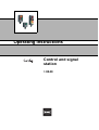
1
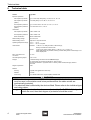
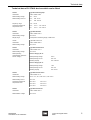
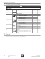
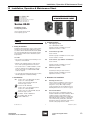
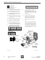
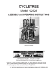
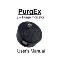
Operating Instructions
Control and signal
station
> 8040
Contents
1
Contents
1
2
3
4
5
6
7
8
9
10
11
12
13
14
15
2
Contents ................................................................................................................2
General Information ...............................................................................................2
Safety instructions .................................................................................................3
Conformity to standards ........................................................................................3
Function .................................................................................................................3
Technical data .......................................................................................................4
Fitting .....................................................................................................................6
Installation .............................................................................................................7
Commissioning ......................................................................................................8
Repairs and Maintenance .....................................................................................9
Accessories and spare parts ...............................................................................10
Disposal ...............................................................................................................10
Type Examination Certificate (Page 1) ................................................................11
Declaration of conformity .....................................................................................12
Installation, Operation & Maintenance Sheet ......................................................13
General Information
2.1 Manufacturer
R. STAHL Schaltgeräte GmbH
Am Bahnhof 30
D-74638 Waldenburg
Telephone:
Fax:
Internet:
+49 7942 943-0
+49 7942 943-4333
www.stahl.de
2.2 Information about the Operating Instructions
ID NO.:
8040606300
Publication Code:
S-BA-8040-en-02-15/06/2007
We reserve the right to make technical changes without notice.
2.3 Purpose of these instructions
Working in hazardous areas, the safety of personnel and plant depends on complying
with all relevant safety regulations.
Assembly and maintenance staff working on installations therefore have a particular
responsibility. They require precise knowledge of the applicable standards and
regulations.
These instructions give a brief summary of the most important safety measures. They
supplement the corresponding regulations which the staff responsible must study.
2
Control and signal station
8040
8040606300
S-BA-8040-en-02-15/06/2007
Safety instructions
3
Safety instructions
Use the station only for its intended purpose.
Incorrect or impermissible use or non-compliance with these instructions invalidates our
warranty provision.
No changes to the station impairing its explosion protection are permitted.
Mount the station only if it is clean and undamaged.
Observe the following when using the station:
X
X
X
X
X
X
X
National safety regulations
National accident prevention regulations
National installation regulations (e.g. IEC 60079-14)
Generally recognized technical regulations
Safety guidelines in these operating instructions
Characteristic values and rated operating conditions on the rating and data plates
Additional instruction plates on the station
Any damage can invalidate the Ex-protection.
4
Conformity to standards
The station complies with the following standards and regulations:
X Directive 94/9/EC
X EN 60079-0, EN 60079-7, EN 61241-0, EN 61241-1
X IEC 60079-0, IEC 60079-1, IEC 60079-11, IEC 60079-18, IEC 60079-7, IEC 61241-0,
IEC 61241-1
Type 8040 station is suitable for use in hazardous areas, zones 1, 2 and 21, 22.
5
Function
Type 8040 control and signal stations are explosion-protected equipments for local
mounting. They are used for control and switching functions in hazardous areas.
8040606300
S-BA-8040-en-02-15/06/2007
Control and signal station
8040
3
Technical data
6
Technical data
Version
Type 8040
Explosion protection
Gas explosion protection
E II 2 G Ex edqm ia/ib [ia/ib] II, IIA, IIB, IIC, T6, T5 or T4
Gas explosion protection
(IECEx)
Ex de ia/ib [ia/ib] m II, IIA, IIB, IIC, T6, T5 or T4
Dust explosion protection
E II 2 D Ex tD A21 IP 65 T 80 °C, T 95 °C, T 130 °C
Dust explosion protection
(IECEx)
Ex tD A21 IP65 T 80 °C, T 95 °C
Certificates
Gas explosion protection
PTB 01 ATEX 1105
Dust explosion protection
PTB 01 ATEX 1105
IECEx certification
IECEx PTB 06.0025
Rated working voltage
max. 690 V, AC
Rated working current
depends on components used
Operating temperature range
- 20 °C ... + 40 °C
- 50 °C ... + 60 °C on request
Cable entries
Standard:
1 x M 25 x 1.5; cable gland 8161; side below (D);
directly mounted into enclosure wall
Special:
in side C (top) and/or side D (below); 1 x M 20 x 1.5; 1 x M 25 x 1.5;
metal cable glands are possible; mounting of metal cable glands in metal flange or via
metal adapter plate
Max. Cross-section for
connection
2.5 mm2
Terminal tightening torque
max. 1.2 Nm
Flanges
In standard design the enclosures are without flanges;
On request they can be fitted with flanges on sides C and D.
Flanges are available in: polyester resin or in brass, powder-coated, dark grey similar to
RAL 7024
Degree of protection
IP 66
Material
Housing
Polyester resin (glass fibre-reinforced)
Gaskets
PU foam
Cover fixing
M 4, cheese head screws, imprescriptible, stainless steel
WARNING
X With ambient temperatures < -20 °C, cable entries „suitable for low temperatures“
must be used, or the station must be so positioned that the cable entries are
mechanically protected.
X The electrical data is affected by the devices fitted. Please refer to the individual type
and rating plates.
)
4
If cable glands other than those manufactured by Fa. R. STAHL Schaltgeräte
GmbH are used, then their degree of protection should be noted.
Control and signal station
8040
8040606300
S-BA-8040-en-02-15/06/2007
Technical data
Technical data of R. STAHL devices which can be fitted:
Version
Type 8010 Indicating lamp
Certificates
PTB 01 ATEX 1160 U
Rated working voltage
20 V ... 254 V
Rated working current Ie
Ex e:
max. 15 mA
Ex i:
max. 150 mA
Frequency range
0 Hz ... 60 Hz
Ambient temperature at
Temperature class
Ex e:
-20 °C ... +55 °C at T6
Ex i:
-20 °C ... +60 °C at T4
Version
Type 8405 Ammeter
Certificates
PTB 01 ATEX 2158 U
Rated working voltage
max. 690 V
Display range
corresponds to measuring range, to DIN 43701
Version
Type 8208 Control unit
Certificates
PTB 01 ATEX 1066 U
Rated working voltage
max. 500 V
Version
Type 8082 Contact block
Certificates
PTB 00 ATEX 1031 U
Rated working voltage
max. 500 V
Rated operating
characteristics referred to
service category
Service category AC 15
Rated operating voltage
400 V
Rated operating current
max. 6 A
Breaking capacity
max. 1000 VA
Service category DC 13
Rated operating voltage
110 V
Rated operating current
max. 6 A
Breaking capacity
max. 110 W
Version
Type 8008 Control switch
Certificates
PTB 00 ATEX 1111 U
Rated working voltage
690 V + 5 %, AC 1, 220 V DC 1, max. 750 V
Rated working current
max. 16 A
Ambient temperature at
Temperature class
T6 at 16 A:
max. 40 °C
T5 at 16 A:
max. 55 °C
T4 at 16 A:
max. 60 °C
Version
Type 8453 Control unit
Certificates
PTB 01 ATEX 1067 U
Rated isolation voltage
max. 550 V
8040606300
S-BA-8040-en-02-15/06/2007
Control and signal station
8040
5
Fitting
7
Fitting
Dimension drawings (all dimensions in mm) - subject to alterations
04582E00
04581E00
04580E00
ConSig 8040/11
ConSig 8040/12
ConSig 8040/13
a [mm]
04584E00
min.
max.
M 20
25
31
M 25
27
33
Additional dimensions for cable glands Series 8161
04579E00
04583E00
Flange
b [mm]
Brass
16
Plastic
16
04585E00
ConSig 8040/23
)
)
6
ConSig 8040/11
and
ConSig 8040/12
combination
Additional dimensions for flanges
When explosion-protected electrical equipment is exposed to the weather, it
is advisable to provide a protective cover or wall.
Transport and storage are only permitted in the original packing.
Control and signal station
8040
8040606300
S-BA-8040-en-02-15/06/2007
Installation
8
Installation
)
To avoid moisture and dirt collecting inside the control stations, electrical
installation must be carried out in a clean and dry environment.
The enclosure may only be opend to carry out installation work and must be
carefully closed again following completion of the work.
Mains connection:
X The conductors must be carefully connected.
X The conductor insulation must reach to the terminal. The conductor itself must not be
damaged (nicked) when removing the insulation.
X Ensure that the maximum permissible conductor temperatures are not exceeded by
suitable selection of cables and means of running them.
)
When terminal sleeves are fitted, they must be gas-tight and applied with a
suitable tool.
Connecting cables to fitted devices with screw terminals:
Where fitted devices have screw terminals, 1 or 2 cables may be connected to a single
terminal. If the conductors are single-strand, both must have the same cross-section and
be of the same material.
Cables may be connected without any special preparation.
Connecting cables to fitted devices with screwless terminals contact block
connections shown as example):
05565E00
05886E00
Intrinsically safe circuits:
Only insulated cables whose test voltage is at least AC 500 V and whose quality is at least
H05 may be used for intrinsically safe circuits.
The diameter of individual conductors may not be less than 0.1 mm. This also applies to
the individual wires of multi-strand cables.
With regard to the insulation and separation of terminals and cables, it should be noted
that the insulation test voltage is derived from the sum of the rated operating voltages of
intrinsically safe and non-intrinsically safe circuits.
In the case of „intrinsically safe against earth“ then the insulation voltage value is at least
500 V (or double the value of the intrinsically safe circuit rated operating voltage).
In the case of „intrinsically safe against non-intrinsically safe“, then the insulation voltage
value is at least 1500 V (or double the rated operating voltage plus 1000 V).
Cables for Ex „i“ circuits must be run at least 8 mm away from the cables of other
intrinsically safe circuits.
8040606300
S-BA-8040-en-02-15/06/2007
Control and signal station
8040
7
Commissioning
The only exception to this is the use of cables in which the cores of the intrinsically safe
or the non-intrinsically safe circuit are surrounded by an earthed screen.
The pre-conditions for the separation between parts to be connected for
intrinsically safe and non-intrinsically safe circuits are:
X a distance of 50 mm around an insulating () 1 mm thick) or earthed metal
( ) 0.45 mm thick) isolating plate or
X an isolating plate which is separated from enclosure walls by a distance of ( 1.5 mm.
9
Commissioning
WARNING
Please convince yourself before operation that the enclosure is completely without
damage.
Before commissioning, ensure that:
X
X
X
X
X
X
X
X
the control station has been installed according to the directions
the control station is not damaged
there are no foreign bodies inside the control station
connections have been made correctly
the cables have been made correctly
all screws and nuts are fully tightened
the cable glands and stopping plugs are securely tightened
unused cable entries are sealed with plugs certified to Directive 94/9/EC, and unused
holes are sealed by stopping plugs certified to Directive 94/9/EC.
WARNING
Excessive tightening of cable glands and stopping plugs can impair the degree of
protection.
)
8
We recommend the use of type 8290 stopping plugs for unused holes and
type 8161 stopping plugs for unused cable entries. Both are available from
Fa. R. STAHL Schaltgeräte GmbH.
Control and signal station
8040
8040606300
S-BA-8040-en-02-15/06/2007
Repairs and Maintenance
10 Repairs and Maintenance
WARNING
Do not open enclosure when supply is switched on!
Do not open when intrinsically safe circuits are energised!
Exception:
Enclosures with intrinsically safe and non-intrinsically safe circuits with the notice
„Non-intrinsically safe circuits protected by IP 30 cover“ may be opened when supplied
with power.
Repairs and maintenance work on the control stations may only be carried out by appropriately authorized and trained personnel.
WARNING
Observe the relevant national regulations in the country of use!
)
If a flameproof device is damaged, absolutely no repair or maintenance work
is allowed. Please replace the device.
For the purpose of maintenance work, the length of time between periodic checks shall
be so set that any system faults likely to arise are found promptly. The maximum interval
between checks is three years.
Note the following when establishing the interval between checks:
X the ambient conditions (installed in the open, wind, rain, sunlight, etc)
X the operating conditions (utilisation of system, operator errors)
X manufacturers’ instructions in technical documentation (mechanical and electrical life
of switchgear)
X big changes in the whole system (e.g. change of zone allocation)
WARNING
Checks should be by sight, adjacent or detailed, depending on local conditions. If faults
are found during these checks which affect the explosion protection, then the system
must be taken out of service until the faults have been cleared.
The following points must be checked during maintenance:
X
X
X
X
clamping screws holding the cables are securely seated
compliance with permitted temperatures (to EN 60079-0)
cracks in plastic enclosures
damage to the gaskets
8040606300
S-BA-8040-en-02-15/06/2007
Control and signal station
8040
9
Accessories and spare parts
11 Accessories and spare parts
WARNING
Use only original spare parts as well as original accessories made by R. STAHL Schaltgeräte GmbH.
Designation
Illustration
Description
Ordering Code
Weight
kg
Plant indentification
label
05603E00
Flange in brass
plain;
for fitting to enclosures 8040;
plasic; paper label
8040001850
0,032
Hole sizes acc. to specification
(up to M 20 x 1,5 2 threaded holes are possible)
8040812490
0,280
with thread 1 x M 25 x 1.5
8040813490
with threads 2 x M 20 x 1,5
8040816490
to fit in factory only on sides C and D
––
05626E00
to fit in factory only on sides C and D
Flange in plastic
05625E00
––
threads acc. to specification
8040815490
0,900
with threads 2 x M 20 x 1,5
8040823490
0,148
with threads 2 x M 25 x 1,5
8040817490
0,900
for earthing metal cable glands;
sides C and D
Brass plate
05633E00
Combination adaptor
set
05616E00
––
threaded holes M 20 x 1,5
8040007550
0,042
threaded hole M 25 x 1,5
8040008550
0,037
8040806290
0,019
for combining 2 enclosures
Attention!
Lower enclosure requires: tapped hole M 25 in side C
(top)
Upper enclosure requires: tapped hole M 25 in side D
(below)
12 Disposal
Observe the national standard for refuse disposal.
10
Control and signal station
8040
8040606300
S-BA-8040-en-02-15/06/2007
Type Examination Certificate (Page 1)
13 Type Examination Certificate (Page 1)
8040606300
S-BA-8040-en-02-15/06/2007
Control and signal station
8040
11
Declaration of conformity
14 Declaration of conformity
12
Control and signal station
8040
8040606300
S-BA-8040-en-02-15/06/2007
Installation, Operation & Maintenance Sheet
15 Installation, Operation & Maintenance Sheet
R. STAHL, INC.
INSTALLATION OPERATION
& MAINTENANCE SHEET
9001 Knight Road
Houston, TX 77054
Tel: 800-782-4357 FAX: 713-792-9301
E-mail: [email protected]
Website: www.rstahl.com
Series 8040
Non-Metallic Control
and Signaling Stations
Please read this entire document
before beginning any work.
3. Component Data
3.1 Pilot Light, type 8010:
12V - 254V AC/DC, 0-60Hz
1. Safety Instructions
Installation and maintenance of these control station
should only be performed by qualified personnel in
accordance with the National Electrical Code (NFPA
70) or the Canadian Electrical Code (CEC) and any
local regulations which relate to hazardous (classified) locations.
Terminal capacity 12-22 AWG. or 2.5 mm2
tightened to 18 in-lbs. or 2 N-m
3.2
600V, 10A max.
Terminal capacity 12-22 AWG. or 2.5 mm2, tightened to 18 in-lbs. or 2 N-m
CAUTION:
• Disconnect power supply before installing or servicing these control stations.
Contact Block, type 8082:
3.3
Control Switch, type 8008/2-0...and 8008/2-1..:
600V, 10A max.
• Operate only undamaged devices with observations of the operating parameters in Section 2.
• For a Class I Zone 1 conduit installation, conduit
seals are required, refer to NEC 505.16 (B) (1).
For any other cable or conduit installation NO
seals are required.
Terminal capacity 12-22 AWG. or 2.5 mm2
tightened to 18 in-lbs. or 2 N-m.
3.4
600V, Ampere rating see data on device
Terminal capacity 12-22 AWG. or 2.5 mm2
tightened to 18 in-lbs. or 2 N-m.
• Use only approved wiring methods for the location,
with the appropriate conduit/cable fittings.
2. Certification
NEC
R
CEC
®
Class I, Zone 1 & 2, AEx ed IIC T6; IP66
Class I, Div. 2, Groups ABCD
Class II, Div. 2, Groups FG; Class III
Enclosure Type 3, 4, 4X
Listed - File No. E182378
Class I, Zone 1 & 2, Ex ed IIC T6; IP66
Class I, Div. 2, Groups ABCD
Class II, Div. 1 & 2, Groups EFG; Class III
Enclosure Type 3, 4, 4X
Certified - File No. LR99480-26
4. Directions for Installation
4.1
Mounting the Enclosure
Using a common screwdriver, remove the four
cover screws. Install the enclosure securely
using #10 to 1/4" (or M5 to M6) mounting
screws, through holes are provided in the box.
Mounting dimensions are as shown on page 3.
4.2
Electrical Installation
There are two types of installation methods:
Conduit installation and cable installation. When
conduit is used the control station(s) were
ordered and delivered with a 3/4" conduit hubs.
When MC-HL cable is used the control station
comes with internal ground plates, with NPT
threads into which the appropriate cable connectors with sealing rings have to be fitted.
II 2 G EEx ed IIC T6; IP66
PTB 01 ATEX 1105
80 406 10 30 0
8040606300
S-BA-8040-en-02-15/06/2007
Ammeter, type 8405:
1
October 13, 2006
Control and signal station
8040
13
Installation, Operation & Maintenance Sheet
R. STAHL, INC.
INSTALLATION OPERATION
& MAINTENANCE SHEET
45 Northwestern Drive
Salem, NH 03079-4809
Tel: 800-782-4357 FAX: 603-870-9290
E-mail: [email protected]
Website: www.rstahl.com
4.3
Installations of Cable Connectors:
6.
Connect conductors to the component terminals (capacity: 12 AWG or 2.5 mm2).
Conductor insulation must reach to the terminals. Tighten all terminals to 18 in.-lb. (including those unused) and secure components on
mounting rail.
7.
Perform a continuity check.
8.
Replace the enclosure cover ensuring
alignment between actuators and internal
components. Actuate the switch and/or
pushbuttons to check for free operation.
9.
Energize the supply circuit and test the
system.
4.3.1 When field installing connectors, use the provided conductive ground metal plates.
4.3.2 Align the ground plate inside the enclosure so
that the threaded hole is centered with the
hole in the enclosure.
4.3.3 Insert the connector through the sealing ring
and screw the connector into the ground plate
inside the enclosure.
4.3.4 Tighten the connector so that the sealing ring
is pressed evenly against the enclosure.
4.3.5 Tighten the set screw on the metal plate to
prevent the connector from loosening.
Note:
The nature of these instructions is only informative and
does not cover all of the details, variations or combinations in which this equipment may be used, its storage,
delivery, installation, safe operation and maintenance.
4.3.6 In case of through wiring the two ground
plates need to be bonded with jumper wire
since the FRP enclosures are non-metallic.
5.
Since conditions of use of the product are outside of the
care, custody and control of the manufacturer, the purchaser should determine the suitability of the product for
his intended use, and assumes all risk and liability whatsoever in connection therewith.
Approved Connector Hardware:
MC / TEK Cable Connectors and Sealing RIngs
Size
MCR Series Connector
Ordering Code
Sealing Ring
Ordering Code
1/2"
MCR050
NCS1
3/4"
MCR075
NCS2
Non-metallic
NPT Close-up Plugs
Size
Ordering Code
1/2"
PD-E-4-0-29-00
3/4"
PD-E-4-0-30-00
SEALING RING
CONNECTOR
METAL PLATE WITH
THREADED HOLE
SET SCREW
TERMINAL
GROUND WIRE
ENCLOSURE WALL
80 406 10 30 0
14
Control and signal station
8040
2
October 13, 2006
8040606300
S-BA-8040-en-02-15/06/2007
Installation, Operation & Maintenance Sheet
R. STAHL, INC.
INSTALLATION OPERATION
& MAINTENANCE SHEET
9001 Knight Road
Houston, TX 77054
Tel: 800-782-4357 FAX: 713-792-9301
E-mail: [email protected]
Website: www.rstahl.com
3.1"
(80 mm)
2.8"
(70 mm)
3.1"
(80 mm)
2.8"
(70 mm)
0.2"
(5.5 mm)
2.8"
(72 mm)
0.3"
(7 mm)
.43"
(11 mm)
2.8"
(72 mm)
0.2"
(5.5 mm)
.43"
(11 mm)
.43"
(11 mm)
A
B
0.2"
(5.5 mm)
ø 0.2"
(ø 5.5 mm)
3.7"
(94 mm)
5.5"
(139 mm)
B
A
ø 0.2"
(ø 5.5 mm)
3.7"
(94 mm)
5.5"
(139 mm)
ø 0.2"
(ø 5.5 mm)
1.9"
(48 mm)
3.7"
(93 mm)
0.3"
(7 mm)
0.3"
(7 mm)
0.2"
(5.5 mm)
3.1"
(80 mm)
2.8"
(70 mm)
2.8"
(72 mm)
A
B
0.2"
(5.5 mm)
3.1"
(80 mm)
2.8"
(70 mm)
2.8"
(72 mm)
.43"
(11 mm)
0.2"
(5.5 mm)
8040/22
8040/12
Compact 8040/11
3.1"
(80 mm)
2.8"
(70 mm)
0.2"
(5.5 mm)
2.8"
(72 mm)
0.2"
(5.5 mm)
3.1"
(80 mm)
2.8"
(70 mm)
.43"
(11 mm)
2.8"
(72 mm)
.43"
(11 mm)
0.2"
(5.5 mm)
8040/64
ø 0.2"
(ø 5.5 mm)
3.7"
(94 mm)
5.5"
(139 mm)
0.2"
(5.5 mm)
7.3"
(185 mm)
5.5"
(140 mm)
B
ø 0.2"
(ø 5.5 mm)
5.5"
(140 mm)
A
ø 0.2"
(ø 5.5 mm)
B
A
7.3"
(185 mm)
0.3"
(7 mm)
0.3"
(7 mm)
0.3"
(7 mm)
0.2"
(5.5 mm)
A
B
0.2"
(5.5 mm)
8040/42
8040/33
3.1"
(80 mm)
2.8"
(70 mm)
3.15"
80mm 2.76"
70mm
.22"
5.5mm
2.8"
(72 mm)
0.2"
(5.5 mm)
.28"
7mm
0.3"
(7 mm)
0.43"
(11 mm)
.43"
11mm
3.82"
97mm
R5
A
B
.22"
5.5mm
5.51"
140mm
5.5"
(140 mm)
B
ø 0.2"
(ø 5.5 mm)
A
7.3"
(185 mm)
7.28"
185mm
.5
0.2"
(5.5 mm)
D
8040/54
80 406 10 30 0
8040606300
S-BA-8040-en-02-15/06/2007
8040/73,84,94
3
October 13, 2006
Control and signal station
8040
15