1
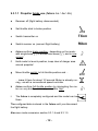
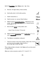
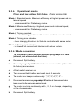
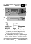
future: speed controller for brushless and sensorless motors operating instructions date of issue: 25 NOV 2000 schulze elektronik gmbh Please read all the instructions carefully (including those who hate to read instructions!) 6 3 5 2 4 1 6 5 4 3 2 1 Key to illustration: 1 Receiver cable, 3-pin: - = negative + = positive p = pulse 2 Battery connection neg (-) 3 Battery connectin pos. (+) 4 Motor connection a 5 Motor connection b 6 Motor connection c black or brown red white or orange black red red white, yellow blue, black Reverse use: blue, black white, yellow red Please note the following guidelines, which apply when you are connecting the motor and reversing its direction of rotation: 1) The controller can be used with sensorless and sensor-controlled motors. If your motor is sensor-controlled, the 5-pin connector is not used. 2) The three motor cables can be connected in any order. 3) To reverse the direction of rotation you have to swap over two of the three motor cables; we recommend that you swap the two outer wires. Unfortunately the colour coding of the motor windings may not apply consistently to the sensor-controlled and sensorless types. Note: for right-hand rotation, Plettenberg motors should be connected as the colour code shows. Mostly futures should be connected with the cooling plate facing the outside of the fuselage. schulze elektronik gmbh prenzlauer weg 6 D-64331 weiterstadt fon: 06150/1306-5, fax: 1306-99 internet: http://www.schulze-elektronik.com e-mail: [email protected] -1- Dear customer, Congratulations on your choice of a future speed controller, which is a microcomputer controlled unit developed and manufactured entirely in Germany, designed for brushless and sensorless 3-phase rotary current motors. All models of the future are amongst the worlds smallest, lightest and most capable speed controllers. The ips (intelligent programming system) which is a standard feature of the ...bo and ...be versions of the future, makes it as simple as possible to configure the controller to match any radio control system. The integral motor connector system is a feature of all future controllers up from 35A nominal current, and makes it possible to remove the unit for servicing, or for fitting in another model, simply by unplugging the cables - no soldering is required. Contents Chapter 1 2 3 4 5 6 7 7.1 7.2 7.3 7.4 8 9 9.1 9.2 9.3.1.1 9.3.1.2 9.3.1.3 9.3.1.4 9.3.2 9.3.3 9.3.4 9.3.5 9.3.6 10 11 12 Subject Warning notes, cautions . . . . . . . . . . . . . . . Ensuring safe, trouble free operation . . . . . . . . Intended applications . . . . . . . . . . . . . . . . Protective circuits . . . . . . . . . . . . . . . . . . Monitor displays . . . . . . . . . . . . . . . . . . . Installing and connecting the unit . . . . . . . . . Legal matters . . . . . . . . . . . . . . . . . . . . . Warranty . . . . . . . . . . . . . . . . . . . . . . . . Liability limits / compensation . . . . . . . . . . . . . CE certification . . . . . . . . . . . . . . . . . . . . . Connection to Tango or Samba-motors . . . . . . Connector systems and mounting instructions . . Using the controller for the first time . . . . . . . . ips - the intelligent programming system . . . . . . . Symbols and terminology . . . . . . . . . . . . . . . Normal operation - propeller brake use (-bo/ -Ko/ -be) No - brake use (-bo/ -Ko/ -be) . . . . . . . . . . . . . Gearbox use (-bo/ -Ko/ -be) . . . . . . . . . . . . . . Mode conversion of -bo/ -Ko/ -be . . . . . . . . . . . future-35Wo/ -45Wo/ -45We/ -55Wo/ -88Wo/ -105Wo. future-80Fo . . . . . . . . . . . . . . . . . . . . . . . future-70Po/ -88Po/ -88Fo/ -111Fo . . . . . . . . . . . future-45He/ -Ho/ -Le . . . . . . . . . . . . . . . . . future-58Ce/ -Co . . . . . . . . . . . . . . . . . . . . Tips . . . . . . . . . . . . . . . . . . . . . . . . . . . Specifications . . . . . . . . . . . . . . . . . . . . Product overview . . . . . . . . . . . . . . . . . . . -2- . . . . . . . . . . . . . . . . . . . . . . . . . . . . . . . . . . . . . . . . . . . . . . . . . . . . . . . . . . . . . . . . . . . . . . . . . . . . . . . . . . . . . . . . . . . . . . . . . . . . . . . . . . . . . . . . . . . . . . . . . . . . . . . . . . . . . . . . . . . . . . . . . . . . . . . . . . . . . . . . . . . . . . . . . . . . . . . . . . . . . . . . . . . . . . . . . . . . . . . . . . . . . . . . . . . . . . . . Page 3 4 5 6 7 7 8 8 8 8 8 9 11 11 11 12 13 14 15 16 18 20 22 24 26 27 28 1 Warning notes, cautions Electric motors fitted with propellers are dangerous and require proper care for safe operation. Keep well clear of the propeller at all times when the battery pack is connected. Technical defects of an electrical or mechanical nature may result in unintended motor runs; loose parts may cause serious personal injuriy and/or property damage. Protect the speed controller from mechanical loads, vibration, dirt and contamination. The CE-certificate on the speed controller does not absolve you from taking proper care when handling the system! Speed controllers are exclusively for use in RC models. Their use in man-carrying aircraft is prohibited. Speed controllers are not protected against reverse polarity (+ terminal and - terminal reversed). Connecting the battery pack to the motor leads of the controller will almost certainly cause irreparable damage. Keep the cables to the motor as short as possible (max. length = 10 cm / 4). Do not exceed the maximum stated length of cable between battery and future (max. length: 20 cm / 7...8"). The wiring inside the battery pack must also be as short as possible. Use in-line soldered stick packs. For the same reason, use a clamp-type amperemeter, not a series meter with shunt resistor. Never leave the flight battery connected when ... ... the model is not in use and/or ... the battery pack is being charged. Electronic equipment is sensitive to humidity. Speed controllers which have got wet may not function properly even after thorough drying. You should send them back to us for cleaning and testing. Although some speed controllers feature a separate On/Off switch, this does not isolate it completely from the battery. Speed controllers can only function properly if they are in full working condition. The protective and monitoring circuits can also only work if the speed controller is in good operating condition. Do not use speed controllers in conjunction with a power supply connected to the mains. Energy reversal can occur when the motor slows down and stops, and this may damage the power supply or cause an over-voltage condition which could damage the controller. Never disconnect the flight pack while the motor is running, as this could cause damage on a speed controller. Please take care when switching off the receiver battery: depending on the receiver you are using, it may send an incorrect throttle signal to the future at this moment, which could then cause the motor to burst into life unexpectedly. If you are using a future with BEC system: a) On no account connect a separate receiver battery or an electronic battery switch (two receiver batteries), as this may cause damage to the speed controller and could cause current to flow from the receiver battery to the motor. b) If you want to use a separate receiver battery cut through the + wire in the receiver cable, or pull it out of the connector if possible. However, for greater protection against motor-inducted interference it is always better to use a speed controller with an optocoupler. In the case of motor failure (e.g.short circuits in the windings) the over-temperature sensor in the controllers may react too slowly to prevent damage. Switch the motor off immediately to prevent permanent damage to the speed controller. Note: Please remember that the monitoring circuits are unable to detect every abnormal operating condition, such as a short between the motor cables. Note also that a stalled motor will only trip the current limiter if the motor's stall current is well above the controller's peak current. For example, if you are using an 80 A controller in conjunction with a 20 A motor, the current monitor will not detect an excessive current even when the motor is stalled. -3- 2 Ensuring safe, trouble-free operation Use only compatible connectors. A 2 mm pin cannot provide reliable contact in a 2.5 mm socket. The same applies with 2mm goldcontact pins and 2 mm tin-plated sockets. throttle stick is (as a rule) in the STOP position (exceptions see Section 9). Please also remember that ... ... the wiring of your RC-components must be checked regularly for loose wires, oxidation, or damaged insulation, especially when using a BEC system. ... your receiver and the aerial must be at least 3 cm (>1") away from motor, speed controller and high-current cables. For example, the magnetic fields around the highcurrent cables can cause interference to the receiver. ... all high-current cables must be as short as possible. Maximum length between flight pack and speed controller should not exceed 20 cm (7"), between speed controller and motor: 10 cm (4"). ... all high-current cables longer than 5 cm (2") must be twisted together. This applies in particular to the motor power cables, which are very powerful sources of radiated interference. ... in model aircraft: half of the receiver aerial's length should be routed along the fuselage, the other half should be allowed to trail freely (take care not to tread on it). Do not attach the end of the aerial to the fin! ... in model boats: half of the receiver aerial's length should be deployed inside the hull above the waterline, the other half should be threaded into a small tube mounted upright. Every time you intend to use the power system - before you turn on the receiver make sure that ... ... no one else is using the same frequency (identical channel number). ... your transmitter is switched on and the Carry out a range check before each flight. Ask an assistand to hold the model aircraft and set the throttle stick to the half throttle position. Collapse the transmitter aerial. Walk away from the model to the distance stated by the RC system manufacturer (this might be a distance of about 50-60 m = 200'). Make sure that you still have full control of the system at this range. As a general rule: receiver interference is more likely to occur when using a controller with BEC system, as these units do not feature an opto-coupler with its optical link. When Ni-Cd batteries approach the end of their charge, voltage falls drastically and quickly. The future detects this and reduces power to the motor automatically. This should leave sufficient energy to bring your model safely back home. However, if you use a small number of cells of high internal resistance and operate at high motor currents, the controller may reduce power before the pack is discharged. You can eliminate this problem by using low resistance straps to connect the cells, or use the direct cell-to-cell soldering technique (sticks) and short, heavy-gauge wire if you assemble your own batteries. Your receiver also benefits from the stability of the voltage supplied from the battery by a BEC system. If the BEC voltage is stable, the receiver is less liable to suffer interference. The CE symbol is your guarantee that the unit meets all the relevant interference emission and rejection regulations when it is in use. If you encounter problems operating the future controller, please note that many problems are due to an unsuitable combination of receiving system components, or an inadequate installation in the model. Important note: Please switch on your transmitter before switching on your receiver. When receiving no transmitter signal some PCM-receiver give no servo-pulse to the output but a constant high voltage. This voltage will set the future after 5 seconds into the brush mode (see section 9.3.8). You can indicate this mode by the double-tone-beep when arming. Please switch back this mode in the same manner. -4- 3 Intended applications: Low voltage types: future-18be: For motors up to 100g (Astro 020, Aveox 1005); 6...10 Ni-Cd/Ni-MH cells; BEC 5V/1,5A; ips. future-25be: For softliners, small sport-models, small ducted fans; 6...10 cells; BEC 5V/1,5A; ips. High voltage types: future-35bo: The controller for high cell numbers, for example as used in ducted-fan models. Battery range 16 - 30 cells; finned heat-sink; ips. future-20Le: Special controller for LMH 110 or helicopters without collective pitch and max. 1 m rotordiameter. 6-10 Ni-Cd/Ni-MH cells; cooling plate; BEC 5V/1,5A. Motor throttles back at under voltage. future-20He: Controller and constant speed regulator for helicopters with max. of 1 m rotor-diameter. 6-8 NiCd/Ni-MH cells; cooling fins; BEC 5V/1,5A. future-45bo: This controller is primarily designed for use in electric gliders or all purposes with non excessive half throtle use. 6 to 17 Ni-Cd / Ni-MH cells. Can be configured using the ips facility. future-35Ho: Controller for helicopters with long durating initial softstart. 16-30 Ni-Cd / Ni-MH cells; cooling rips; fixed stick positions for neutral and full throttle. Normal speed controller and constant rpm use. Autorotation use. future-55bo: The high-current controller for high cell count. Batt. range 16...30 cells; finned heat-sink; ips. future-55Wo: The high-current controller for high cell count. 16...30 cells; finned heat-sink; ips-boat. future-80Fo: The thoroughbred controller for 27-cell competition gliders with geared motos. Only for brief operation: 5 seconds followed by 15 seconds pause. Use with 16 - 28 cells, 1000 or 1250 mAh capacity. Fixed stick travels; brake cannot be disabled; heatsink; 72 FETs. 4 motor-modes, see section 9.3.4. future-45be: Identical to the future-45bo, but with the addition of a BEC system. Thats why can be used with 6 - 12 cells. future-45Ko: The controller for longer durating half throttle as used in sport models, aerobatic models or ducted fan models. Batt. range 6 - 17 cells; finned heat-sink; ips. Highlights common to all units: Ultra-small, ultra-light units. A crucial point for all modellers who require max. performance combined with minimum weight. future-45We/45Wo/88Wo: The special controller for boats. Splash water protection. Cooling plate with tubes, -88Wo no water cooling. 6-12 / 7-17 cells, ipsboat. 4 different timings. future-45He/Ho: Controller for helicopters with long durating initial softstart. 6-10 Ni-Cd / Ni-MH cells (...He), up to 17 cells (...Ho version); cooling rips; fixed stick positions for neutral and full throttle. Normal speed controller and constant rpm use. Autorot. use. future-58bo: This version can be used with 7 to 17 NiCd cells in any model where the capacity of the 45A version is marginal, and where the 90A type would represent a sledgehammer to crack a nut. With its improved efficiency it is also a good choice in models where cooling can be problematic. The intended applications therefore include small hotliners and small ducted-fan models. Can also be configured using the ips facility. future-58Ce/Co: the special controller for 10th scale cars. 6-10 Ni-Cd / Ni-MH cells. ips-car (Fixed stick travel, learning neutral point; proportional brake/no brake); cooling fins. future-70/88Po: The special controller made for pylon racers. Full throttle use with 7-10 Ni-Cd cells. Extra leightweight, short and low profile. Fixed stick travels; brake cannot be disabled. 4 different timings. 88Po for F5D. future-88Fo: Speed controller for 10-cell glider competition work. Can be used with 7 - 17 cells. Fixed stick travels; brake cannot be disabled. 4 timings. future-111Fo: For those who require even more than 90 A in 10-cell competition work. Can be used with 7 - 17 cells. Fixed stick travels; brake cannot be disabled. 4 different timings. Better than 250-step resolution over the whole control range for extremely fine speed control. Controllers work reliably right down to the last scrap of energy in the battery pack. Auto-arm function and power on reset. ips (intelligent programming system) with no pots! The speed controller automatically configures itself every time to the stick travel when you switch your receiver on respectively you connect your battery pack. The brake can also be disabled in the same way if required. ips also includes a special setup variant for geared motor systems. Fixed stick travel between braking point and full-throttle point, softstart for throttle and brake. It is normally essential to apply full-throttle at the start of the flight. This variant only learns one stick position (brake point) when in use. Fine-tuning the system to match the transmitters stick travel is still possible, but must be done by adjusting the travel at the transmitter. During the configuration process the motor acts as a loudspeaker to give you audible confirmation of the procedure. Naturally all future are suitable for use in model boats provided that it is protected from contact with water by our water shielding conformal coating. Connecting Tango/Samba-motors: see section 7.4 -5- 4 Protective circuits Note: the monitor circuits are effective, but they cannot detect every possible operating condition. Temperature monitor: The temperature monitor switches off the motor. You can reset the unit using the "autoarm" function (throttle stick to stop for about 2 sec.) If the motor windings are shortcircuited the temperature monitor reacts too slowly to prevent damage. Switch the motor off immediately to avoid permanent damage to the speed controller. As soon as the voltage of the drive battery falls back to the 5V threshold the motor is throttled back. If the situation which caused the controller to throttle back continues for more than a short time, the unit switches the motor off. Of course, you can re-start the motor again briefly by moving the throttle stick back to "stop" for about 2 seconds to re-arm the system. If you use a future with opto-coupler you retain full control of the model until the receiver battery is flat; if you use a future with BEC system the power system and the model remain fully controllable until the last usable energy in the flight pack is exhausted. We can not predict how long you can still control your model with the residual battery charge as this depends on many parameters such as the number of cells in the pack, the cell type, actual motor current and the way you control your model. The only solution is for you to time the period yourself with the model on the ground. If the voltage monitor trips, i.e. the motor starts to throttle back without your intervention, you should stop the motor at once with the throttle stick in any case so that you have the maximum possible reserve of power. Our future controllers feature a current Maximum speed monitor: If maximum rotational speed of the motor will exceed, future throttles down. In this state do not use longer then 1 second. future bo or ko types cut off instantly. Because of this: Do not run motor without airscrew. Minimum speed monitor: Voltage monitor: Current monitor: monitor circuit which trips when the current rises above the specified maximum value. If the motor is stalled, the motor is throttled back. This means, that a motor which draws an excessive current will never reach fullthrottle, and the current may stay below the specified maximum value. If future is some seconds in current limiting mode, it will disarm itself (switching off the motor). To ensure that the controller detects the rotor position reliably, this series of future types sets a defined minimum rotational speed. If the rotor speed falls below this value continuously, the controller switches the motor off. You can over-ride the reset with the autoarm function (throttle stick to stop for about 2 sec). This protective function can cause the motor to be reluctant to start up if its torque limit is exceeded. If you are using one of the ...bo types with V03 software the only time you may notice this is when you first start the motor after changing the battery. In this case a propeller one step smaller in diameter must be used. If this should happen, check that the maximum permissible motor current is not exceeded. Receiver signal monitor: If the receiver signal fails, or the signal is longer or shorter than the usual range of values, the smart controller reverts to hold mode for few seconds before switching to disarmed mode. Reverse polarity protection: These speed controllers are not protected against reversed polarity! Watchdog: If this circuit is tripped the speed controller stops working briefly and then reverts to normal operation. -6- 5 Monitor displays The future is fitted with LEDs to indicate its operating status disarmed, neutral or brake enabled. the set stick end-points are (in dependence of the used future-type or ips-mode) confirmed by a beep from the motor or a barely reciptible "blip" in full-throttle position when normal using with activated brake. However, when the unit is being configured 6 Installation, connections Installing in the fuselage: Length of connecting cables: Velcro (hoop and loop) tape is the ideal method of mounting the controller in the fuselage. Do not pack the future in foam as this may lead to a heat buildt-up in the controller. The cables to the flight battery and - in particular to the motor - should be kept as short as possible. Long cables tend to act as aerials and radiate interference; they also add unnecessary weight. See also section 2. Receiver connection: Power-connection battery <--> future: Connect the receiver cable attached to the future to the receiver servo output corresponding to the throttle stick on the transmitter (or a switch if that is your preference). Do not exceed the maximum stated length of cable between battery and future (max. length: 20 cm / 7...8"). Otherwise controller can be damaged. The future receives its control signal via this receiver socket. It is essential to use polarized gold-platedcontact connectors - fitting any other type of connector invalidates the warranty. If you use a future with BEC system, power is supplied to the receiver via the same cable. Check regularly especially in this case that the receiver cable is undamaged and firmly seated at the future. On no account connect a separate receiver battery or an electronic battery switch (two receiver batteries), as this may cause damage to the speed controller. Connectors which do not have a polarised insulator can be made safe (i.e. polarised) by soldering the futures positive battery wire to a socket, and the futures negative wire to a plug. We recommend that you choose your connectors from our selection in Section 8. Power-connection future <--> motor: Cut down the existing motor cables to a length of no more than 10 cm. Locate the cables with the pp35 plugs supplied with the controller (plugged into the future), and solder them to the motor cables. See separate sheet (page 1) for details of cable configuration. Avoid pulling on the motor cables; we recommend that you secure the three motor plugs with glass-reinforced tape to prevent them being pulled out. -7- 7 Legal matters 7.1 Warranty conditions damage or costs which arise from the incorrect or incompetent use of our products, or are connected with that use in any way. In so far as the law allows, our obligation in respect of compensation, regardless of the legal grounds, is limited to the invoice value of that quantity of goods which was immediately involved in the event which caused the damage. This does not apply if legally binding regulations oblige us to accept unlimited liability in a particular case, or if deliberate or gross negligence can be proved on our part. All schulze products are 100% dynamically tested by using a battery and a motor. We do not simulate tests. If your unit develops a problem, please return it to schulze or to the importer. Include a description of the problem. Please be careful and precise, and list the battery voltage and capacity, motor type, conditions under which failure occured etc. A note saying doesn't work does not help us much, and it may lead to waisted time in troubleshooting. Before returning the unit for repair, please test it one more time carefully. If we find that the controller is operating correctly, whether it is under warranty or not, we will make a charge for our lost time. Warranty claims are processed according to our current General Conditions of Business, which are printed in our catalogue. 7.3 CE certification The products described in this manual are manufactured in accordance with all specific and mandatory European CE guidelines: EMI 89/336/EEC, 91/263/EEC and 92/31/EEC. The products have been tested according to the following norms: EMI-emissions: EMI-resistance: One further note: If a problem arises with a schulze device, send it straight back to us or our authorized representative (see catalogue); dont attempt to repair it! This allows us to repair it as quickly as possible, as we can detect warranty defects without any doubt and thus keep costs low. You can also be certain that we will fit genuine replacement parts which are a perfect match to your device. (Very few hobby shops are equipped to analyze and repair surfacemount printed circuit boards.) We reserve the right to refuse repair to units which have been modified or improved by unauthorized experts. You also have the comfort of a properly repaired unit with a renewed warranty. The warranty period of repaired devices is applicable only to the repair. This period is shorter than the warranty period of a new product (See general conditions of business). EN 50 081-1:1992 EN 50 082-1:1992 or EN 50 082-2:1995 The design and construction of our products comply with the requirements for safe operation. EMI emissions were tested under realistic conditions, i.e. using suitable motors close to the maximum allowed currents. The use of resistors instead of motors do not create maximum emission levels. Further testing is carried out to ensure adequate EMI resistance against emissions from other apparatus. The RF signals used for these tests are similar to those produced by mobile telephones and RC transmitters. We wish to point out again that our products are tested under realistic conditions for the most dangerous scenario: exposed to the field of a powerful transmitter, the motor must not start while you are working on the model. Problems involving our products are most likely caused by unsuitable combinations of radio components or improper installations. Liability limits / compensation 7.4 Connection to Tango and Samba motors We at Schulze Elektronik GmbH are unable to monitor methods of installation and operation, and have no control over how you fit, use and maintain the devices we produce. For this reason we accept no liability for loss, At this time we do not recommend the use of future with any of these motors. A special version of future with higher switching frequency is being designed especially for these motor types. 7.2 -8- 8 Connector systems and mounting instructions 8.1 3.5 mm gold-contact connector system (pp35); max. load > 80A + red plug wide sleeve narrow socket + red ( battery akku) future - black socket narrow sleeve wide plug - black ( akku) Caution: remove locating lug from battery cable. Do not remove lug from any cables attached to controllers or charge leads! Manufacturers information: the pp35 plug is very short, and this presents the danger that the spring contact could lose its resilience due to excessive heat build-up during the soldering process. You can side-step the problem by keeping the temperature below 200°C as follows: either remove the contact carefully before soldering, or simply push the plug into a piece of wet fine-grain sponge for soldering, or plug it in a 3.5 mm hole of a copper-block. Fit the connectors in the order shown above; the contacts are pressed in as follows: a. Place plastic sleeve vertically on table, grip end up. b. Push contact down into sleeve. c. Place 2.5mm wide screwdriver blade on top of cable solder joint inside sleeve. d. Tap screwdriver to press contact into sleeve until latch engages. 8.2 4 mm gold-contact connector system (CT 4, also CT 2); max. load > 80A + red sleeve wide plug socket sleeve narrow red ( battery - black akku) future sleeve narrow socket plug sleeve wide black ( akku) Fit the connectors in the order shown above; the contacts are pressed in as follows: a. Rest plastic sleeve on vice jaws with cables hanging down. b. Close vice jaws until cables are just free to move. c. Fit plug into socket and tap into sleeve until latch engages. d. Fit socket onto plug and tap into sleeve until latch engages. -9- 8.3 + red MPX gold-contact connector system (green or red); max. load ~30A heat-shrink socket plug heat-shrink + red ( battery - black akku) future heat-shrink socket plug heat-shrink -black ( akku) Fit the connectors in the order shown above; the contacts are soldered as follows: a. To center the contacts fit plug and socket together before soldering. b. Tin all 6 exposed contacts of plug or socket. c. Fit cable end into triangle of contacts, solder to all three contacts. d. Position heat-shrink sleeve and shrink over joint. 8.4 + red 2,0 / 2,5 mm gold-contact connector system; max. load ~30A socket sleeve wide plug + red ( + locating nose + battery - black sleeve narrow socket sleeve narrow sleeve wide akku) future plug -black ( akku) Fit the connectors in the order shown above; the contacts are pressed in as follows: a. Place plastic sleeve vertically on table, grip end up. b. Push contact down into sleeve. c. Place 2.5mm wide screwdriver blade on top of cable solder joint inside sleeve. d. Tap screwdriver to press contact into sleeve until latch engages. - 10 - 9 Initial use 9.1 ips, the intelligent programming system for configuring the future to suit your application The ips reflects the initial set-up procedure used with our speed controllers until recently, i.e. the process of adjusting the braking point with the help of a trim pot. For any normal application with an EMF brake (for a folding propeller) the start-up procedure is entirely conventional: throttle stick to "motor stopped", switch first transmitter-, then receiver on, hold model in lauch position, apply full throttle, launch. The controller has to be adjusted to match the stick travel of your transmitter - a procedure we term "configuration" - and with these units the process is fully automatic. The brake point and the full throttle point must be configured in such a way that full stick travel is always available to operate the motor, as this provides the finest possible level of control. If you wish to use the controller in a model which does not require a propeller brake the procedure is slightly different (see below). The ...Fo types do not feature user configuration facilities. The brake and full-throttle positions are pre-set and fixed. If you have a transmitter with adjustable servo travel we recommend that you set throttle-servo to normal full travel, i.e. +/- 100%. Adjust Multiplex servo center pulse width to 1.5 ms (= -22% center). A single beep mostly indicates that the controller is armed! When you next move the throttle stick, the motor will start running. If the future beeps twice when the transmitter stick is at the brake position (double beep = full-throttle position). disconnect the controller and operate the servo reverse facility on your transmitter, otherwise the controller would arm itself (single beep) at the full-throttle setting of your transmitter and would run at full throttle with the stick at the stopped position - the exact opposite of what is required. (future-Fo/-Po/-Wo shows operational mode). 9.2 Symbols and terminology Stick: The throttle stick on the transmitter Neutral position (self neutralising stick) Idle position (position where the motor just barely runs) or stop position (brake). Brake position or idle position Position of the throttle stick where the motor stops or just barely runs. Full-throttle position 100% voltage passed to the motor. Wait (0.5 seconds) Audible indicators: These indicators are only audible when a motor is attached, as the motor itself acts as the loudspeaker. Single beep Double beep Double tone Momentary interruption in running (inverse beep) - 11 - e ee ee (e) 9.3.1.1 Propeller brake use (future -bo / -be/ -Ko) a Receiver off (flight battery disconnected) b Set throttle stick to brake position c Switch transmitter on TXon d Switch receiver on (connect flight battery) RXon e future confirms brake position - depending on the mode with single-beep (e) or double-tone beep (ee), and is now armed! f Hold model in launch position, keep clear of danger area around propeller! g Move throttle quickly to full-throttle position and ... e ... leave it there for about 1/2 second. Motor is already running - as with a conventional speed controller h future confirms full-throttle position by interrupting the motor run very briefly - a barely perceptible "blip" i The future is completely configured and the model can be flown The configured data is stored in the future until you disconnect the flight battery. Also see mode conversion section 9.3.1.4 and 9.3.1.5 - 12 - (e) 9.3.1.2 No-brake use (future -bo / -be/ -Ko) a Receiver off (flight battery disconnected) b Set throttle stick to full-throttle position c Switch transmitter on TXon d Switch receiver on (connect flight battery) RXon e future confirms full-throttle position - depending on the mode - with double single-beep (e e) or double doubletone beep (ee ee). f Move throttle quickly to idle position and ... ee ... leave it there for about 1/2 second g future confirms idle position with a single beep (e or ee), and is now armed! h The future is completely configured i Place the model in the launch position. Keep clear of danger area around propeller. Open throttle in the normal way to start the flight. The configured data is stored in the future until you disconnect the flight battery. Also see mode conversion section 9.3.1.4 and 9.3.1.5 - 13 - e 9.3.1.3 Belt-drive use (future -bo / -be/ -Ko) Sets trottle and brake to a longer soft-start. Fixed stick travel: Full throttle = Stopp position + 0.6 ms. a Receiver off (flight battery disconnected) b Set transmitter stick to centre position (technically: 1.5 +/- 0.15 ms pulse width) c Switch transmitter on TXon d Switch receiver on (connect flight battery) RXon e future detects gearbox use, confirms - depending on the mode - with triple single-beep (e e e) or triple doubletone beep (ee ee ee). eee f only for no brake use, skip if brake is necessary: Move transmitter stick to full throttle position and leave it there until motor beeps twice (ee oder ee ee). g Move transmitter stick quickly to brake / neutral position and leave it there for half a second. (technically: pulse width less than 1.35 ms) h future learns brake / neutral position, calculates full-throttle position (brake / neutral position + 0.6 ms), confirms with single beep (e or ee) and is now armed! i The future is completely configured and is ready for use. j Moving the transmitter stick towards full throttle starts the motor running. The model can be launched. The configured data is stored in the future until you disconnect the flight battery. Also see mode conversion section 9.3.1.4 and 9.3.1.5 - 14 - ee e 9.3.1.4 Operational modes (future-18be/ -20Le/ -25be from version 6; -be/ -bo/ -Ko from version 14) Mode 1: Standard-mode (single beep e) - Maximum efficiency at highest power and rotational speed. Mode 2: Timing retarded (double tone beep ee). - use when having problems with runtime and/or too much current with Aveox, Lehner and Hacker motors (RPM/volt tables of these manufacturers fits better with this mode). - Maximum of motor-efficiency changed to lower currents. 9.3.1.5 Mode conversion The conversion must be done with the prog-adapt-2/3 cable (optional, not delivered with the future). Alternatively mode can be changed by making a short circuit on the plug/ socket of the receiver cable between the pulse lead (orange, yellow or white) with the 5V-BEC-voltage (red lead). In that case do not connect receiver cable to the receiver. a Disconnect flight battery. b Connect prog-adapt-2/3 cable between receiver cable (attached to the future) and receiver. c At first switch receiver on. d Then connect flight battery and wait about 3 seconds, then ... e The motor beeps 1* with old mode beep. Within 1 second after beep ... f Disconnect prog-adapt-2/3 cable from future receivcer cable. g The motor beeps 1* with old mode beep. Within 2 seconds after beep ... h Connect prog-adapt-2/3 cable to the future receiver cable again. i The motor now beeps continuously with the new mode beep tone. j Disconnect and remove prog-adapt-2/3 cable. k Disconnect flight battery. - 15 - 9.3.2 future-35Wo/ -45Wo/ -45We/ -55Wo/ -88Wo/ -105Wo Unbraked (ips-boat) Half stick travel - self neutralising or Full stick travel - non self neutralising Splashproof design BEC 5 V / 3 A in future-45We, otherwise opto coupler a Receiver off and drive battery disconnected b1 Set transmitter stick to centre position (technically: 1.5 +/- 0.15 ms pulse width) or b2 Set transmitter stick to idle position (technically: pulse width less than 1.35 ms) or c Switch transmitter on TXon d Switch receiver on (connect drive battery) RXon e1 future learns centre position, calculates full-throttle position (neutral position + 0.3 ms pulse width) or future learns idle position, calculates full-throttle position (idle position + 0.6 ms pulse width), e2 confirms with beep(s) (beep count according to operational mode) and is now armed! f e(eee) Moving the transmitter stick towards full throttle starts the motor running. The configured throttle positions are stored in the future until you disconnect the drive battery. The configured operational mode is stored in the future until you change the mode. - 16 - 9.3.2.1 Operational modes boat- future (from version 5w) Mode 1: Standard-mode. Maximum efficiency at highest power and rotational speed; recommended for Plettenberg motors. Mode 2: Timing retarded. - use when having problems with runtime and/or too much current. Mode 3: Timing more retarded. - when changing Kontronik to Schulze controller with same motor. - not for Plettenberg motors. Mode 4: Timing most retarded - for lowest idle current with Hacker and Lehner motors. - not for Aveox or Plettenberg motors. 9.3.2.2 Mode conversion of the boat-future The conversion must be done with the prog-adapt-2/3 cable (optional, not delivered with the future). a Disconnect drive battery. b Connect prog-adapt-2/3 cable between receiver cable (attached to the future) and receiver. c At first switch receiver on. d Then connect drive battery and wait about 5 seconds. e The motor now beeps continuously: 1*, 2*, 3*, 4*, 1*, 2* ... f Disconnect and remove prog-adapt-2/3 cable at the moment when beep count is the same as desired mode. g The motor confirms continously with 1, 2, 3 or 4 beeps, depending on the chosen mode. h Disconnect drive battery. - 17 - 9.3.3 future-80Fo (F5B-Sailplane) Fixed stick positions: brake = 1.2 ms, full throttle = 1.8 ms a Receiver off (flight battery disconnected) b Set transmitter stick to brake position (technically: pulse width less than 1.2 ms) c Switch transmitter on d Connect flight battery, future confirms with power-on beeps e Switch receiver on RXon f The future detects brake position, confirms with beep(s) (beep count according to operational mode) and is now armed! e(eee) g The future is completely configured and is ready for use h Moving the transmitter stick towards full throttle starts the motor running i The model can be taken off TXon - 18 - eee ee 9.3.3.1 Operational modes future-80Fo (from version 8d) Mode 1: Limit 120 000 rpm P4; - only for following high rpm contest motors: HP220/20/A2P6 5:1 or 7:1 @ 24-28 cells and AVEOX 14HC06Y1 @ 24-27 cells. Mode 2: Limit 58 000 rpm P4; - future...bo programm with high rpm accelleration. HP220/30/A3P4 5:1 and 7:1 @ 16-28 cells, HP370/30/A2 @ 16 - 28 cells - Well suited for Aveox, Hacker, Ikarus and Lehner motors, but not for mode 1 motors! Mode 3: Limit 83 000 rpm P4; - Mode for following motors: Aveox: 14HC06Y1,5 3.7:1 @ 16-28 cells, F27 @ 16-28 cells, 1412Y2 3.7:1 @ 16-28 cells. Kontronik: KBM: 42-30 6.7:1 @ 16-24 cells, 42-24 5.2:1 @ 16-27 cells, 52-18 3.7:1 @ 16-28 cells. Mode 4: Timing sharper as mode 3, limit 95 000 rpm P4; - Limit not well suited for all motors of mode 3!!! 9.3.3.2 Mode conversion The conversion must be done with the prog-adapt-2/3 cable (optional, not delivered with the future). a Disconnect flight battery. b Connect prog-adapt-2/3 cable between receiver cable (attached to the future) and receiver. c At first switch receiver on. d Then connect flight battery and wait about 5 seconds. e The motor now beeps continuously: 1*, 2*, 3*, 4*, 1*, 2* ... f Disconnect and remove prog-adapt-2/3 cable at the moment when beep count is the same as desired mode. g The motor confirms continously with 1, 2, 3 or 4 beeps, depending on the chosen mode. h Disconnect flight battery. - 19 - 9.3.4 future-70Po/ -90Fo/ -111Fo (F5D-Pylon and F5F-Sailplanes) Fixed stick positions: brake = 1.2 ms, full throttle = 1.8 ms a Receiver off (flight battery disconnected) b Set transmitter stick to brake position (technically: pulse width less than 1.2 ms) c Switch transmitter on TXon d Connect flight battery, future confirms with power-on beeps ee e Switch receiver on RXon f The future detects brake position, confirms with beep(s) (beep count according to operational mode) and is now armed! e(eee) g The future is completely configured and is ready for use h Moving the transmitter stick towards full throttle starts the motor running i The model can be taken off - 20 - eee 9.3.4.1 Operational modes Pylon and low voltage FAI future (from version 6b) Mode 1: Standard mode. Maximum efficiency at highest power and rotational speed; - recommended for Plettenberg motors. Mode 2: Maximum efficiency at highest power and rotational speed; - recommended for Plettenberg motors. Mode 3: Timing retarded. - use when having problems with runtime and/or too much current. Mode 4: Timing more retarded. - when changing Kontronik to Schulze controller with same motor. Mode 5: Timing most retarded - for lowest idle current with Hacker and Lehner motors. 9.3.4.2 Mode conversion The conversion must be done with the prog-adapt-2/3 cable (optional, not delivered with the future). a Disconnect flight battery. b Connect prog-adapt-2/3 cable between receiver cable (attached to the future) and receiver. c At first switch receiver on. d Then connect flight battery and wait about 5 seconds. e The motor now beeps continuously: 1*, 2*, 3*, 4*, 1*, 2* ... f Disconnect and remove prog-adapt-2/3 cable at the moment when beep count is the same as desired mode. g The motor confirms continously with 1, 2, 3 or 4 beeps, depending on the chosen mode. h Disconnect flight battery. - 21 - 9.3.5 future-__He/ - __Ho/ -20Le (Helicopter) Fixed stick positions: idle (off)=1,1 ms, full throttle=1,9 ms. Note: If you are using a Graupner RC system this equates to +/- 100% stick travel. If you find that you cannot arm the controller reliably, the solution is to increase servo travel to about 105%...110%. In speed regulator mode the full throttle setting on a slider should be different - according to the maximum rotational speed you require - and must not be necessarily 100%. Important: If you are using the future as a normal speed controller in your helicopter, you must connect the futures servo cable to the receiver output which produces the throttle curve set on the transmitter when you operate the collective pitch control. If you are using the future as a speed regulator (governor), you must not connect the controller to the receiver channel which produces the throttle curve. Instead connect it to a channel which is controlled directly by a slider or rotary control on the transmitter, i.e. a channel not affected every time by the collective pitch control. If you ignore this, motor speed will change every time you give a collective pitch command. 9.3.5.1 Standard controller mode a Receiver off (flight pack disconnected) b Set transmitter stick to idle position (motor off) c Switch on transmitter TXon d Switch on Receiver (connect flight pack) RXon e future detect idle setting, confirms with beep and is armed f future is completely configured and ready to use g Move the transmitter stick towards full throttle, and the motor starts running. h The helicopter can be flown - 22 - e 9.3.5.2 Speed regulator mode (constant rotor head speed) (not available in future-20Le - but timing is possible to adjust; see section 9.3.1.4) a Receiver off (flight pack disconnected) b3 Regulator mode 6-, 8- and 10-pole motors (high rpm): Set slider to maximum possible pulse widths (full throttle) (in technical terms: pulse widths 1.5 ... 1.9 ms) c Switch on transmitter d Switch on Receiver (connect flight pack) f future detect idle position, confirms with 2- or 3 beeps (according to mode) e Move slider to minimal possible pulse widths (motor off) (in technical terms: pulse widths lower 1.1 ms) f future detect idle sitting, confirms with beep and is armed g future is completely configured and ready to use h Move slider in the direction of full-throttle to set the rotor speed you require (see below) i The helicopter can be flown or b2 Regulator mode 2- and 4-pole motors (low rpm): Set slider slightly above idle (motor start) position. (in technical terms: pulse widths 1.15...1.5 ms) TXon RXon ee(e) e Tip: To provide finer control of the pre-set rotor speed, set up the slider channel on the transmitter so that the full-throttle end-point correspondends to the maximumrotor speed you ever need (e. g. for aerobatics). You can achieve this by reducing servo travel, and/or adjusting the neutral point if necessary. Speed ranges of armed future, relating to 4-pole motors: Low rpm: Slider at 1,15 ms = 3,966 rpm; Slider at 1,9 ms = 28,935 rpm High rpm: Slider at 1,15 ms = 7,931 rpm; Slider at 1,9 ms = 57,870 rpm Important: Regulation is also switched to different characteristics. Auto-rotation: If the slider channel is moved back to minimum speed by a mixer (not to the motor stopped position, but to about 1.18 ms (Graupner=-80%)), the integral softstart designed for manual speed changes is reduced to the point where an auto-rotation can be interrupted quickly by suddenly (switch, no soft start) opening the throttle again. Under-voltage: As soon as the voltage of the drive battery is not high enough the motor is throttled back first. Later future is switched off. Reception interruption: (from Version 7h resp. 5f) To show interferences, RPM is slightly reduced. After about 1 second persistant interferences, motor shuts down. Remedy the problem before starting again. See hints in section 2 and 10. - 23 - 9.3.6 future-58Ce/ -58Co (ips-car) Proportional brake Half stick travel - self neutralising or Full stick travel Splashproof design BEC 5.7 V / 3 A a Receiver off (drive battery disconnected) b Set transmitter stick to centre position (neutral) (technically: 1.5 +/- 0.15 ms pulse width) c Switch transmitter on TXon d Switch receiver on (connect drive battery) RXon e future learns neutral position, calculates full-throttle position (neutral position + 0.3 ms) and brake position (neutral position - 0.3 ms) confirms with single beep and is now armed! f The future is completely configured, the model can be used g Moving the transmitter stick towards full throttle starts the motor running h Moving the transmitter stick towards full brake slows the model proportionally e The configured data is stored in the future until you disconnect the drive battery. - 24 - 9.3.6.1 Operational modes (from version 5) Mode 1: Standard-mode (single beep e) - Maximum efficiency at highest power and rotational speed. Mode 2: Timing retarded (double tone beep ee). - use when having problems with runtime and/or too much current with Aveox, Lehner and Hacker motors (RPM/volt tables of these manufacturers fits better with this mode). - Maximum of motor-efficiency changed to lower currents. 9.3.6.2 Mode conversion The conversion must be done with the prog-adapt-2/3 cable (optional, not delivered with the future). Alternatively mode can be changed by making a short circuit on the plug/ socket of the receiver cable between the pulse lead (orange, yellow or white) with the 5V-BEC-voltage (red lead). In that case do not connect receiver cable to the receiver. a Disconnect flight battery. b Connect prog-adapt-2/3 cable between receiver cable (attached to the future) and receiver. c At first switch receiver on. d Then connect flight battery and wait about 3 seconds, then ... e The motor beeps 1* with old mode beep. Within 1 second after beep ... f Disconnect prog-adapt-2/3 cable from future receivcer cable. g The motor beeps 1* with old mode beep. Within 2 seconds after beep ... h Connect prog-adapt-2/3 cable to the future receiver cable again. i The motor now beeps continuously with the new mode beep tone. j Disconnect and remove prog-adapt-2/3 cable. k Disconnect flight battery. - 25 - 10 Tips Rotational speeds: future speed governors and controllers generally produce higher rotational speeds than Kontronik controllers. In order to maintain the same load on the motor, this requires a change to a motor pinion around 10% smaller (i.e. around 1 - 2 teeth) when you switch to the future, otherwise you will overload the motor. Start-up problems, controller / governor faults: We have now established that the usual cause of unreliable motor start-up problems is poor contact in the connectors. Inadequate contact can result in faults due to excessive voltage, especially when the highvoltage versions of the future are used, because the high resistance of the connectors prevents the voltage being passed back into the battery at mid-range settings, and especially during braking. Examples of poor practice: Solder between the contact segments of the plug - Remedy: solder on a brand-new plug. Resin (electronic solder flux) under the contact segments of the plug - Remedy: remove flux residues with meths or contact cleaner. Over-long leads between battery and future - Remedy: shorten to permissible length (chapter 6). Lack of spring pressure in the contact segments - Remedy: solder on brand-new plugs, and be sure to cool the segments when soldering. Poor-quality connectors, i.e. oxidised sockets (black inside). Discoloured gold plating (greenish or grey) - Remedy: use high-quality plugs and sockets from a brand-name manufacturer - Remedy: dont use cheap goods from the Far East - Remedy: contact segments should be made of copper-beryllium - no mild steel contacts! Overheating motors: If you are using a Graupner Carbon 70, Hacker, Kontronik BL or Simprop motor, never shorten the winding wires which project from the motor. The strands are coated with high-temperature lacquer, and it is impossible to solder through this material. To obtain a sound soldered joint you must mechanically remove the lacquer coating all round each individual strand. Any strands which are not soldered or fractured cause an increase in current flow through each remaining wire, and this in turn causes an increase in motor temperature. Helicopter motors (efficiency / temperature): For helicopter applications the motors maximum efficiency should be around 15 A, and not at the maximum currents which can occur briefly in aerobatics. Oscillation of RPM (helicopters): - test future in normal speed controller mode. If you have further oscillation of the back, gyro is adjusted in wrong manner and/or rear servo is too slow and/or lever mechanics is too weak. - Belt drive especially of the main gear has to be adjusted with enough tension! Multi-motor operation: In general terms we do not recommend operating multiple motors with a future. From some of our customers we have heard that this certainly works with some (but not all) Aveox, Hacker and Lehner motors, provided that the currents do not exceed the permissible maximum values for the speed controller concerned. However, we cannot guarantee that both motors will rotate over the full load range. It is never permissible to run more than one Plettenberg motor connected to a single future: you must use a separate future for each motor. However, you can certainly power both controllers from a single drive battery. - 26 - 11 Specifications Weight: Excluding - including cables Current rating: Nominal current / maximum current: The excess current level lies above the maximum current value for each unit. The nominal current value is the continous current at full throttle at which the future can be operated when connected to a 2 Ah battery (1 Ah for -18be, -25be, -20He; 1250 mAh 80Fo). Throttle, brake: Internal resistance of the MOSFETs, based on data sheet values (25°C / 10 V gate voltage). At 125°C the resistance is about 40% higher. For this reason you should always provide an effective flow of cooling air over the future to prevent it getting too hot. Pulse times: General: Allowed range: 0.8 ms ... 2.5 ms, cycle time: 10 ... 30 ms. Gearbox-mode: Brake point <1.35 ms, fixed travel brake point <-> full throttle: ~0.6 ms. future-__Fo: Fixed brake point = 1.2 ms, fixed full throttle point = 1.8 ms. Rotational speed: the rotational speed stated above is the limit value for a 4-pole motor (...P4). The following multiplication factors apply: P2= *2; P4= *1; P6= *0.67; P8= *0.5; P10= *0.4. The speed limiter provides some level of protection against the armature magnets of HP 220 motors flying off. Note: this speed limit is too high for the washing machine motor types. BEC: The stated peak current is dictated by the maximum current value of the 5V voltage regulator; it can only flow for less than 0.5 seconds, followed by a cooling-off period. The stated continous current is much lower and is determined by the maximum power dissipation of the voltage regulator used in the unit (Vloss = Vbattery- 5 V BEC-voltage). Pay attention when connecting micro-servos: the current consumption is mostly 2...3 times higher than the current of the Graupner C341 servo! The BEC System can be overload by temperature when using more than 8 cells and more than 3 servos! Power dissipation ~3.0W (i.e. at 14 V = 333 mA continuous current) Pulse frequency: up to about 10 kHz for the ...bo types, up to about 20 kHz for the ...Fo types. The higher pulse frequency of the ...Fo controller types provides improved behaviour under acceleration, but leads to greater heat build-up in the part-load range. Soft-start: the soft-start feature on throttle and brake is not the same for the standard versions and the FAI versions; it is matched to the requirements of each application (FAI = short). Temperature: Overtemperature threshold approximately 110°C. Note: If you have been using a sensor-controlled speed controller, you may find that now your motors maximum speed is different when you use the future. The timing of sensor-equipped motors is set for a particular rotational speed and a particular load (similar to the advance setting of an internal combustion engines timing), but the future automatically optimises the timing for maximum efficiency under all load conditions. This means that the timing does not depend on the position of the speed sensors as dictated by the mechanical design, nor on the accuracy with which they are installed. The net result is that you may find that the maximum rotational speed of your motor is higher - combined with higher current; or lower - combined with lower current. For this reason it may prove necessary to experiment with new propeller sizes when you make the switch to a sensorless controller. - 27 - 12 Product overview Type Current Ni-Cd Size Weight Cable Thrott. Brake Rot.Sp. Version Special features unit [A] [cells] [mm] [g] [mm2] [mW] [mW] [min-1] Common Airplane: future-18be future-25be future-45bo future-45be future-45Ko future-58bo 18/24 25/33 45/60 45/60 45/60 58/77 6-10 6-10 6-17 6-12 6-17 7-17 50*25*10 50*25*12 74*24*12 74*24*17 74*24*14 74*24*12 16-21 18-23 25-35 32-42 28-38 25-35 1.5 1.5 2.5 2.5 2.5 2.5 6.5+7 4+4.7 2.2*2 2.2*2 2.2*2 1.4*2 6.5/3 4/3 2.2/3 2.2/3 2.2/3 1.4/3 63000 63000 63000 63000 63000 63000 7i 7i 14a 14a 14a 14a 15 FETs,BEC5V/1.5A 15 FETs,BEC5V/1.5A 36 FETs BEC 5V / 3A 36 FETs, w.cool.rips 36 FETs future-35bo future-55bo 35/45 55/70 16-30 16-30 81*24*14 81*24*19 28-38 37-50 2.5 2.5 4.0*2 2.0*2 4.0/3 2.0/3 63000 14a 63000 14a 36 FETs, w.cool.rips 72 FETs, w.cool.rips 58/77 58/77 6-10 6-10 69*24*14 69*24*17 27-37 33-43 2.5 2.5 1.4*2 1.4*2 1.4/3 1.4/3 63000 5e 63000 5e 36 FETs, w.cool.rips BEC 5.7V/3A, cool.rips future-88Fo future-111Fo 88/130 111/148 7-17 7-17 74*24*14 74*24*16 29-44 31-50 4,0 4.0 0,7*2 0.7*2 0,7/3 0.7/3 84000 8b 84000 8b 36 FETs, w.cool.plate 72 FETs, no cool. plate future-80Fo 80/110 16-28 81*24*19 37-50 2.5 2.0*2 2.0/3 120000 9d 72 FETs, w.cool.rips future-20Le future-20He future-45Ho future-45He 20/33 20/33 45/60 45/60 6-10 6- 8 6-17 6-10 50*25*12 50*25*14 74*24*14 74*24*17 18-23 20-25 28-38 34-44 1,5 1.5 2.5 2.5 4+4,7 4+4.7 2.2*2 2.2*2 - 63000 7L 63000 7h 63000 5f 63000 5f 15 FETs,BEC,cool.plate 15 FETs, BEC,cool.rips 36 FETs, w.cool.rips BEC 5V/3A, w.cool.rips future-35Ho 35/45 16-30 81*24*14 29-39 2.5 4.0*2 - 63000 5f 36 FETs, w.cool.rips 6-17 6-12 7-17 7-17 74*24*18 74*24*24 74*24*14 74*24*18 37-51 44-58 31-46 43-58 2.5 2,5 4,0 4,0 2.2*2 2,2*2 0,7*2 0,7*2 - 63000 63000 63000 63000 6w 6w 6w 6w 36 FETs, w.cool.tubes BEC 5V/3A,w.cool.tub. 36 FETs, w.cool.plate 36 FETs, w.cool.tubes Car: future-58Co future-58Ce Contest (FAI): Helicopter: Boat (Water): future-45Wo future-45We future-88Wo future-105Wo 56/65 56/65 88/130 105/130 future-35Wo future-55Wo 42/50 65/80 16-30 16-30 81*24*18 81*24*23 37-51 50-63 2,5 2.5 4,0*2 2.0*2 - 63000 6w 63000 6w 36 FETs, w.cool.tubes 72 FETs, w.cool.tubes 70/120 88/130 7-10 7-10 69*24*10 69*24*11 21-31 26-41 2.5 4,0 1.4*2 0,7*2 1.4/3 0,7/3 84000 8b 84000 8b 36 FETs, thin, leightw. 36 FETs, thin, leightw. Pylon: future-70Po future-88Po Conversion to and from brushed motor mode Brushed motor mode is not longer available from production date 23.8.00 because of new improvements. The future-...bo,Co,Ce,Wo could be used to control conventional motors at up to 2/3 of the controllers nominal current. These motors must be connected to the outer two sockets marked motor. - 28 -


![取扱説明書[NA-FA90H1/80H1] (19.01 MB/PDF)](http://vs1.manualzilla.com/store/data/006721095_3-74aed6b56d4142fd0743047762967916-150x150.png)