1
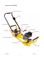
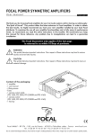
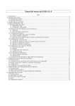
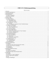
Catalogue No. RS200H
Operating and Maintenance
Instructions
Rail Scrubbing Machine
Permaquip Ltd
Brierley Industrial Park, Stanton Hill, Sutton-In-Ashfield, Nottinghamshire, NG17 3JZ
Tel: +44(0)1623 513349 Fax: +44(0)1623 517742
www.permaquip.co.uk
[email protected]
Contents
1.
Contents
2.
Introduction and Specifications
3.
Benefits of using the RS200H
4.
Warnings and Safety Instructions
5.
Risk Assessment
6.
Features of the RS200H
7.
How does the RS200H unit work?
8.
Starting the RS200H
9.
Using the RS200H
10.
Further notes
11.
Maintenance Instructions
12.
General Maintenance Details
13.
General Maintenance Details
RS200Iss7
3-Sep-07
1
Introduction
The RS200H unit has been designed to allow rapid and easy cleaning of railhead in
situations where train borne equipment is either too expensive or impractical.
The RS200H unit is for use by a single operator on short stretches of track where a
clean rail head is required quickly.
The RS200H unit must only be used by correctly trained personnel under the
supervision of a properly certified individual and all relevant “Network Rail” standards
and safety requirement must be strictly adhered to at all times.
Any and all adjustments to the equipment must be carried out in a “position of safety”
and never on or near the line.
Specifications
Dimensions
Height (handle upright):
Width:
Length:
985mm
335.5mm
1140mm
Weight:
47kg
Noise emissions:
75.5dBA no load (adjacent to operator)
89dBA full load (adjacent to operator)
Vibration readings:
Aeq Σ8.42ms2
Time to reach EAV (Exposure Action Value) –
42mins/man per day.
Time to reach ELV (Exposure Limit Value) –
2hrs 50mins/man per day.
See www.hse.gov.uk/vibration for further information.
Engine:
Type:
Power
Engine oil capacity:
Engine oil type:
Fuel tank capacity:
Fuel type:
Spark plug:
Honda GX160
4kW (5.5hp) at 3600rpm
0.65l
SAE 10W-30
2litres
Unleaded
NGK BPR5ES
RS200Iss7
3-Sep-07
2
Benefits of using the RS200H Rail Scrubber
•
Immediate low cost solution to contaminated rail heads ensuring a “clean” line in
minutes.
•
The RS200H is fitted with two 25watt/12volt lamps that make working in the dark
much easier.
•
The RS200H unit is lightweight, easy to handle, is self powered and is easily
operated and maintained by a single operator.
NOTE:- Due to (HSE) lifting requirements the unit will need two operators in order
to lift the unit onto the track initially but, in an emergency, the unit is light enough
to be removed from the track by one operator.
•
The RS200H unit is safe to operate, incorporating a dead man’s handle to ensure
that the wire scrubber brush is stopped quickly when the unit is de-activated.
•
The working parts of the scrubber are covered to ensure that the operator is
protected from all moving parts when the unit is in operation.
•
All the controls are mounted within easy reach of the operator to eliminate the
need to “bend over “ the unit during operation
•
The unit has been designed with a “wide handle” to allow for two handed “safe”
operation giving good control over the unit in use.
•
The operating parts are vibration isolated from the operator contact to reduce
operator fatigue and discomfort.
RS200Iss7
3-Sep-07
3
Warnings and Safety instructions.
Read these instructions carefully before operating, maintaining or servicing this product.
Please keep these instructions in a safe accessible place.
Read and observe the following
safety precautions and warnings.
Careless or improper use of this
equipment may result in serious or
fatal injury.
Always wear a dust mask,
safety goggles and ear
protection. Wear a helmet
where applicable.
WARNING!
Indicates instant possibility of
severe personal injury or loss of
life, if instructions are not
followed.
CAUTION!
Indicates a possibility of
personal injury or equipment
damage, if instructions are not
followed.
Operator Safety
Tool Safety
•
•
•
•
•
•
•
•
•
•
Always read the instructions carefully so as
to avoid any injury or damage when
unfamiliar with this equipment.
Always wear heavy clothing, boots and
gloves. Do not wear loose clothing, short
pants, sandals etc. and ensure that long hair
is tied up above shoulder length.
Do not operate this equipment when tired, ill
or under the influence of alcohol, drugs or
medication.
Never allow an inexperienced person to
operate this equipment.
Keep all carrying handles and levers free
from oil.
Keep hands away from the wire brush when
it is rotating. Ensure that it has stopped
rotating before touching the wire brush.
Never use a larger diameter wire brush than
specified for use with this equipment.
Ensure that the wire brush being used is free
from damage.
Wear safety goggles when operating the
machine.
•
•
Inspect the entire piece of equipment
before use.
Replace damaged components, lubricate
where necessary and ensure that all
fasteners are secure.
Use only accessories that have been
recommended by the manufacturer.
Failure to do so could result in damage to
the product and may invalidate the
warranty.
WARNING!
Never modify the product in any way. Do not
use your equipment for any job other than for
which it is intended.
Maintenance safety
•
•
Maintain according to the manufacturers
recommended procedures.
Use only genuine replacement
components as recommended by the
manufacturer.
Transport and Storage
•
•
Before moving the product, ensure that the wire brush has stopped rotating.
After use, clean the equipment and accessories, and store in a dry place.
RS200Iss7
3-Sep-07
4
Features of the RS200H
Dead man’s lever
Throttle
Lifting handle
Scrubbing wheel
Petrol cap
Honda engine
Rear light
Air filter
Brush operating lever
Base-frame
Front light
RS200Iss7
3-Sep-07
5
How does the RS200H Work
The RS200H unit is pushed manually along the rail to be cleaned. The cleaning
brush mounted beneath the unit “scrubs” the rail as the unit is pushed along.
The brush is driven by the engine drive shaft.
The engine incorporates an electronic cut-off feature to ensure that the rotation of
brush is stopped when the handle is released.
NOTE:- Do not attempt to place the RS200H unit on the track or dismount it whilst
the engine is running.
The RS200H unit is a petrol driven unit and requires checking and maintenance at
each use as well as regular maintenance at specified intervals (see the maintenance
section for details).
Mounting and Dismounting the RS200H
Note: Although the RS200H has rollers fitted with ball races, it cannot be pushed
along the ground.
The RS200H has a weight of 47kg, and as such should only be lifted by two people.
Once on the track, the handle should be extended and the clamping screws
tightened and locked in the upright position.
The machine must be lifted
onto the track by 2 men
using the lifting handles.
Once on the track, lift the handle
and tighten the two locking knobs.
RS200Iss7
3-Sep-07
6
Starting the RS200H
Important
Before starting the engine, the user is responsible for checking the level of oil and the
level of the fuel. Ensure that only UNLEADED fuel is used.
Ensure that relevant safety equipment has been provided and is in use .viz. Safety
glasses, ear defenders, dust mask, safety hat etc.
Before starting the RS200H, ensure that the brush operating lever is in the lifted
position as shown below. The starting procedure can now commence.
Before attempting to start the engine,
ensure that the brush operating lever is
in the lifted position.
Push the fuel switch to the on position.
If starting the engine from cold push
the choke lever to the on position.
(Located above the fuel switch)
RS200Iss7
Turn the engine on/off switch to
the on position.
Hold the dead man’s lever.
Set the throttle lever to ¾’s.
Pull the engine start cord sharply.
3-Sep-07
7
Using the RS200H
Once the engine has started, leave the throttle lever in the ¾’s position and leave the
choke in on position (if started cold) until the engine has warmed up enough to
maintain idle speed. Switch the choke to the off position when the engine has
warmed up.
Never attempt to start the engine if the scrubber wheel is in contact with the rail head.
Increase the speed of the engine to normal running speed by moving the throttle to
the “hare” position. Move the brush operating lever to the forward position to allow
the wheel to come into contact with the rail head.
The operator must ensure that he has a tight hold on the machine when lowering the
brush as it will try to drive along the track.
The operator can now move slowly down the track length to be treated, moving in
both directions if necessary, to remove the contaminants.
The engine can be stopped at any time simply by releasing the dead man’s lever.
This action causes the engine to stop.
The machine is fitted with two 12v/25watt
lights. This is to facilitate rail scrubbing when
used at night. The lamps are powered whilst
the engine is running.
RS200Iss7
3-Sep-07
8
Further notes
NOTE:
Before attempting to treat a section of rail, ensure that all relevant “Network Rail” and
local instructions are in force and are being adhered to.
•
If at any time it is required that the unit be pushed along the track without the
need to clean the rail, the rail scrubber brush should be lifted back up to prevent
any damage occurring to the brush by sliding it along the track, with the engine
stationary. This can be performed either with the engine running or not. If the
distance involved is excessive, then the engine should be stopped.
•
When dismounting the unit for removal from site, the engine should be stopped
and a second operator called to help lift the unit from the track.
•
Never lift the unit from the track whilst the engine is running as this could cause
instability.
•
If at any time the unit stops, do not attempt any repairs whilst the unit is on or
near the line. Always remove the unit to a “position of safety” to carry out any
maintenance or adjustments.
RS200Iss7
3-Sep-07
9
Maintenance Instructions
Schedule of Maintenance - Engine
Regular service should be carried out at every indicated month or operating hour
intervals whichever occurs first.
Task
Engine oil
Air Cleaner
element
Spark plug
Spark arrester
Valve clearance
Fuel filter
Fuel tube
Lamp bulb
Wire brush
Drive belt
Each
use
Check level
Change
Check
Change
Clean-adjust
Change
Clean
Check-adjust
Check
Change
Check/Change
If necessary
Check/Change
If necessary
Check/Change
If necessary
Check
Change
First
month
or 20hrs
Every 3
months or
50hrs
Every 6
months or
100 hrs
Annually
or 300hrs
*
*
*
*
*
*
*
*
*
*
*
*
*
*
*
*
*
*
*
*
Engine Oil :- In areas where extremes of temperature are likely to be encountered
please consult the engine manufacturers literature:NOTE:- SAE 10W-40 is recommended for general use.
Engine oil capacity for the GXV 160 is 0.65 litres. (refer to the engine manufacturers
maintenance manual for details of how to check oil level, top up oil and drain the
sump to replace with fresh oil)
NOTE:- The engine manufacturer’s maintenance manual is supplied with this
manual.
NOTE:- An operator trained in the use and maintenance of this machine can carry
out the tasks shown in red. All other tasks, should be carried by a qualified fitter or
Tracman service engineer.
RS200Iss7
3-Sep-07
10
General Maintenance Details
Exhaust
Petrol cap
Air Filter cover
Fuel Safety
●
●
●
●
●
●
Fill the engine with 4 stroke fuel only.
Fill in a well ventilated area.
Use a petroleum approved container for the fuel.
Do not smoke or allow others to smoke when using or refueling the machine.
When refueling, stop the engine and allow it to cool before filling.
Clean up all fuel spills before starting the engine.
Air filter cleaning :The air filter should be checked at every use and if found to be obstructed with
debris, should be replaced. The filter should be replaced in any case every 3 months
or every 50 hours running. (see the engine manufacturers maintenance manual for
details of how to replace the air filter.)
NOTE:- If the RS200H unit is used in a very dusty environment, it may be necessary
to check and replace the air filter more frequently, as the cleanliness of the air filter
has a direct effect on the efficiency of the engine.
Spark Plug :For location of the spark plug and details of setting see the engine manufacturers
maintenance manual. The spark plug setting should be checked/replaced every 6
months or every 100 hours running.
All these items require to be inspected at least once a year (see the engine
manufacturers maintenance manual for details)
Lamp Bulb:The lamp bulbs should be checked at each use by starting the engine.
If necessary, the bulbs can be replaced by peeling back the rubber outer, to release
the lens and parabola. This will expose the bulb bayonet fitting. Replace the bulb with
our part number RS200-LUB and refit the lens and parabola.
RS200Iss7
3-Sep-07
11
General Maintenance Details
Drive Belt :The drive belt should be checked after the first month of use and replaced on a
quarterly basis thereafter. Unscrew and remove the guard covering the drive belt.
Ensure that there is only around ½” of lateral movement on the belt.
Remove the guard to expose
the drive belt to check for
excessive play
Remove the two grubscrews
retaining the taper-lock bush
on the drive pulley
Screw the grubscrews into the
jacking holes to release the
taper-lock bush
Remove the taper-lock bush
and replace the belt. Re-fitting
is a reversal of this procedure
Scrubber Brush:Check and replace when necessary. Use the spanners supplied to remove the
retaining lock-nut. Remove the wheel and refit the new one.
NOTE:It is essential that the above maintenance schedules are adhered to, in order to keep
the RS200H unit in good running order. This will ensure that the RS200H unit will
perform well each time it is used.
RS200Iss7
3-Sep-07
12
General Maintenance Details
Recommended spares
RS200Iss7
3-Sep-07
13
General Maintenance Details
Recommended spares
RS200Iss7
3-Sep-07
14
General Maintenance Details - Recommended spares
Item No
Drg No
Description
No. off
1
RS200-01A
ROLLER
2
2
RS200-01B
AXLE
2
3
RS200-02
SCRUBBER CHASSIS
1
4
RS200-03
SCRUBBER LOWER HANDLE
1
5
RS200-15A
SCRUBBER CARRY HANDLE LH
2
6
RS200-15B
SCRUBBER CARRY HANDLE RH
2
7
RS200-16A
SCRUBBER LIFTING HANDLE
2
8
RS200-20
ANTI-VIBRATION MOUNT ASSY
2
9
RS200-21
BRUSH DRIVE SHAFT
1
10
RS200-22
BRUSH BEARING HOUSING
1
11
RS200-23
71 X 1 SPA 1108 PULLEY
2
12
RS200-23A
V BELT A730MC A27.5MN 13X700LI
1
13
RS200-24
SWING ARM
1
14
RS200-25
MOTOR PLATE
1
15
RS200-32
BELT GUARD
1
16
RS200-33
BRUSH GUARD
1
17
RS200-34
SEE ITEM 11
18
RS200-35
PULLEY SPACER WASHER
19
RS200-36
BRUSH SPACER WASHER
1
20
RS200-37
BRUSH RETAINING WASHER
1
21
RS200-38
SPRING GUIDE
2
22
RS200-40
ACTUATING LINK
1
23
RS200-41
ACTUATING ARM
1
24
RS200-42
SPRING GUIDE
2
25
RS200-45
ACTUATING HANDLE
1
1
26
27
RS200-56
50MM SPACER
2
28
RS200-57
20MM SPACER
2
29
30
RLS4Z(LINKS10)
BEARING
4
31
RS200-HA1
HANDLE BAR UPPER
1
32
RS200-HA2
THROTTLE CONTROL LEVER
1
33
RS200-HA3
HANDLE BOLT BAR
2
34
RS200-HA4
TRI-HAND WHEEL
2
RS200-HA8
DEAD MANS LEVER
1
37
RS200-HA9
HAYTER THROTTLE HANDLE FLEX 1834
1
38
RS200-LU
RS200 12V LAMP PT.N0.56-01-00
2
39
RS200-LUB
LAMP BULB LUCAS PT.LLB335T
2
40
RS200-23B
1108 X 25MM DIA. TAPER LOCK BUSH
1
41
RS200-34A
1108 X 3/4" DIA. TAPER LOCK BUSH
1
42
RS200-22A
BEARING 6905ZZ
3
43
RS200-SB1
6" DIA.X 2" BRUSH
1
44
SC660CAP
M6 X 60 LG CAPSCREW
6
45
SC860CSK
M8 X 60 LG CSK SCREW
8
46
SC824CSK
M8 X 25 LG CSK SCREW
8
47
FWR-M10
M10 FLAT WASHER
6
48
NYLOC-NUT-M10
M10 NYLOC NUT
4
49
FB1060
M10 X 60 LG BOLT
2
50
NUT-M16
M16 NYLOC NUT
1
35
36
RS200Iss7
3-Sep-07
15
General Maintenance Details - Recommended spares
Item No
51
52
53
54
55
56
57
58
59
60
61
62
63
64
65
66
67
68
Drg No
SC615CAP
SC1016SB
LINKS12
SC1025SB
SC1020SB
SET840
SPWR-M8
NYLOC-NUT-M8
SPWR-M6
NYLOC-NUT-M6
DWL-6X15
SC635CAP
SC840CAP
SC812CAP
FB1040
NUT-M10LOCK
NUT-M8LOCK
GX160
Description
M6 X 15 CAPSCREW
M10 X 16 LG SHOULDER BOLTS
RETURN SPRING
M10 X 25 LG SHOULDER BOLTS
M10 X 20 LG SHOULDER BOLTS
M8 X 40 Lg SET SCREW
M8 SPRING WASHER
M8 NYLOC NUT
M6 SPRING WASHER
M6 NYLOC NUT
6 DIA.X 15 LG DOWEL
M6 X 35 LG CAP SCREW
M8 X 40 LG CAP SCREW
M8 X 12 LG CAPSCREW
M10 X 40 LG BOLT
M10 LOCK NUT
M8 LOCK NUT
HONDA GX 160 ENGINE
No. off
3
1
2
1
1
2
12
12
5
5
1
1
4
2
1
For further information and spares contact:
Permaquip Ltd
Brierley Industrial Park, Stanton Hill
Sutton-In-Ashfield, Nottinghamshire, NG17 3JZ
Sheffield
S9 5JF
Tel: 01623 513349
Fax: 01623 517742
www.permaquip.co.uk
[email protected]
RS200Iss7
3-Sep-07
16