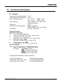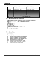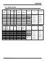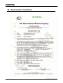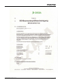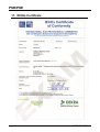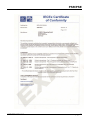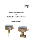
1
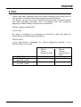
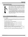
Operating Instructions
for
Paddle Flow Monitor
Model: PSR-..., PSE-...
PSR/PSE
1. Contents
1.
2.
3.
4.
5.
6.
Contents ........................................................................................................ 2
Note .............................................................................................................. 3
Instrument Inspection .................................................................................... 4
Regulation Use.............................................................................................. 4
Operating Principle........................................................................................ 5
Use in Hazardous Areas (PSx-2) .................................................................. 5
6.1. General ................................................................................................ 5
6.2. Electrical Contact ................................................................................. 6
6.3. Potential equalisation ........................................................................... 6
6.4. Electro-Static ....................................................................................... 6
7. Mechanical Connection ................................................................................. 7
8. Electrical Connection .................................................................................... 8
9. Limit Switches ............................................................................................... 8
10. Maintenance ............................................................................................... 10
11. Technical Information .................................................................................. 11
11.1. General .............................................................................................. 11
11.2. Model Label for IEC-Ex-Version ........................................................ 12
11.3. Model Code ....................................................................................... 12
12. Order Codes ............................................................................................... 13
13. Recommended Spare Parts ........................................................................ 16
14. Dimensions ................................................................................................. 16
15. Declaration of Conformance ....................................................................... 17
16. Examination Certificate ............................................................................... 18
17. IECEx Certificate ......................................................................................... 20
Manufactured and sold by:
Kobold Messring GmbH
Nordring 22-24
D-65719 Hofheim
Tel.: +49(0)6192-2990
Fax: +49(0)6192-23398
E-Mail: [email protected]
Internet: www.kobold.com
page 2
PSR/PSE K07/1212
PSR/PSE
2. Note
Please read these operating instructions before unpacking and putting the unit
into operation. Follow the instructions precisely as described herein.
The devices are only to be used, maintained and serviced by persons familiar
with these operating instructions and in accordance with local regulations
applying to Health & Safety and prevention of accidents.
Machine guidelines 2006/47EC
No CE mark
By usage in machines, the measuring unit should be used only when the
machines fulfil the EWG-machine guidelines.
PED 97/23/EG
In acc. with Article 3 Paragraph (3), "Sound Engineering Practice", of the
PED 97/23/EC no CE mark.
Pipe
Table 8
Group 1
dangerous fluids
PSR-.. (1/4" - 1")
PSR-1132B
and PSR-1140B
PSR-1232B
and PSR-1240B
PSR/PSE K07/1212
Art. 3, § 3
not deliverable
Table 9
Group 2
non-dangerous
fluids
Art. 3, § 3
Art. 3, § 3
Cat. II
Art. 3, § 3
page 3
PSR/PSE
3. Instrument Inspection
Instruments are inspected before shipping and sent out in perfect condition.
Should the damage to a device be visible, we recommend a thorough inspection
of the delivery packing. In case of damage, please inform your parcel service/
forwarding agent immediately, since they are responsible for damages during
transit.
Scope of delivery:
• Paddle Flow Monitor
• Operating Instructions
Model: PSR-.. / PSE-..
4. Regulation Use
Series PSR and PSE are used to monitor liquid flow. Instruments are provided
with an adjustable limit switch. Only low viscosity fluids that are compatible with
the material combination chosen are allowed to be monitored. If using higher
viscous media, large deviations in the specified switching range will occur.
The instruments are relatively insensitive to dirt, however large particles may
block the paddle, leading to erroneous alarm conditions; likewise, ferritic particles
may deposit on the magnet and lead to faulty operation. In case of doubt, please
contact the manufacturer.
page 4
PSR/PSE K07/1212
PSR/PSE
5. Operating Principle
The KOBOLD flow monitors of series PSE and PSR are used
where economical, reliable flow monitors are indicated.
Depending on the flow velocity respectively flow rate, the baffle
plate is deflected and moves the permanent magnet via the
balance arm into the switching range of the reed contact
mounted outside of the flow media.
The flat spring, which also serves as a support for the balance
arm, forces the baffle plate back to its rest position when there
is no flow. KOBOLD baffle plate flow monitors are supplied
completely assembled with fitting up to nominal size 40, or for
larger nominal pipe sizes - supplied without a pipe length for
direct insertion into standard T pieces or fittings. The sealing
takes place via PTFE tape.
6. Use in Hazardous Areas (PSx-2)
6.1. General
The paddle flow switch, being a mechanical component, has no inherent potential
ignition source. The mounted contact is suitable for usage in Ex-zone IIC and I as
an intrinsically safe component.
The measurement units can be used as follows:
In the Zone 0 (Gas-Ex, Cat. 1G) into explosion-group of IIA, IIB and IIC
In the Zone 20 (Dust-Ex, Cat. 1D)
In the Zone 2 (Gas-Ex, Cat. 3G) into explosion group of IIA, IIB and IIC
In the Zone 22 (Dust-Ex, Category 3D)
In the Zone 1 (Gas-Ex, Cat. 2G) into explosion group of IIA, IIB and IIC
In the Zone 21 (Dust-Ex, Category 2D)
In hazardous areas 1 and 2 in underground mining (category M1 and M2)
Regulation usage does not cause any zone inside the fitting or at paddle.
Exceptions are possible during start-up and shut-down of the plant.
The Paddle Flow Monitor is filled completely with medium under normal
operation. Zone 2 or zone 1 conditions may be obtained for a short time.
PSR/PSE K07/1212
page 5
PSR/PSE
The ambient temperature limit area is fixed as follows:
Medium Temperature
Model
NBR-seal
FPM-seal
PSR-2132**;
-20....+70 °C -20...+110 °C
PSR-2140
all other
-20...+70 °C -20...+110 °C
Pmax
25 bar
100 bar
6.2. Electrical Contact
The paddle flow switch can directly switch intrinsically safe circuits in Ex-zone or
may be used in intrinsically safe current circuits in combination with a certified
switching amplifier. The electrical connection is explained in chapter 8 “Electrical
Connection”.
6.3. Potential equalisation
The all metal flow meters are to be incorporated in potential equalization system
of the plant. This is achieved via metallic connection pipe.
6.4. Electro-Static
The devices are to be protected against electrostatic unloading. The case of the
device is to be earthed electro-statically (for example with metal pipes). Besides,
the local potential balance is to be established according to local regulations.
The wires must be protected in the installation in the hazardous area “0” against
electro-static unloading. This can be done by using conducting pipes and rigid
covers.
page 6
PSR/PSE K07/1212
PSR/PSE
7. Mechanical Connection
Before installation
• Please check that the actual flow matches with the
switching range of the instrument.
• Ensure that the allowable maximum operating
pressure and operating temperature of the
instruments will not be exceeded.
• Remove all transport packing and be sure that no
packing material is left in the instrument.
• The instrument may be installed in any position
(except PSR-..32 / PSR-..40 - for horizontal
installation only); however, the top half of the paddle
switch must be vertically positioned in relation to the
pipe axis, and the arrow on the threaded fitting must match the flow direction.
• For dirty media, it is recommended that the upper housing will be installed as
close to vertical as possible, respectively with not more than 40° deviation from
vertical. This will prevent dirt from being deposited in the upper housing. When
this is not possible, we recommend the instrument to be cleaned more
frequently (see maintenance).
• The application of PTFE tape or similar sealant to the connection threads is
recommended.
• Check that the connection threads of the pipe are fully sealed.
Attention! Make sure that the supply voltage to the instrument conforms to
the value stated on the equipment label. For higher power loads, we
recommend our contact protection relay model MSR-10.
The inlet and outlet section needs to be minimum 5 x DN in front of and after the
flow meter.
PSR/PSE K07/1212
page 7
PSR/PSE
8. Electrical Connection
• Ensure that the electrical supply lines are powerless.
• Connect the connection cable with your supply cable.
• The contact housing is made of glass-fibre reinforced plastic.
It is insulated in accordance with VDI 0720 Class II; separate
insulation measures are not necessary.
After connecting the external equipment, the instrument is ready for operation.
9. Limit Switches
The instrument is supplied with an adjustable contact. The standard contact,
depending on the adjustments can be used either as N/O or N/C switch. The
instrument is supplied ex works as a normally open contact. Optionally, the
PSR/PSE can be ordered with an SPDT switch.
Contact mode
Depending on the positioning of the adjustable standard switch, the following
contact modes are available.
• Normally open
The contact closes when the flow increases and the set point value is reached
or exceeded. The switch opens again with falling flow at the minimum value
based on the switch hysteresis.
• Normally closed
The contact opens when the flow increases and the set point value is reached
or exceeded. The switch closes again with falling flow at the minimum value
based on the switch hysteresis.
• Option: Changeover (SPDT) contact
The normally open and normally closed switch modes are simultaneously
available from the same position. When retrofitting the standard design with an
SPDT switch, the upper switch housing must be replaced at the same time.
page 8
PSR/PSE K07/1212
PSR/PSE
Switch Point Adjustment
When adjusting the switch point, the clamp plate in the top of the upper housing
must be loosened, enabling the switching unit to be repositioned. For ease of
adjustment, the switching unit is marked with a blue, white or red arrow (not with
the SPDT switch option). The front edge of the clamp plate serves as the
adjustment marker.
• Normally open contact
(standard setting, as shipped)
The switch range is adjustable in the
area of the red arrow. By sliding the
switching unit in the direction of flow,
the minimum switching value given in
the table is achieved. By sliding the
switching unit in the opposite direction,
the maximum listed switch value is
achieved.
• Normally closed contact
The switch range is adjustable in the area of the blue (white) arrow. By sliding
the switch unit in the direction of flow, the minimum switch value given in the
table is achieved. By sliding the switch unit in the opposite direction, the
maximum listed switch value is achieved.
• Option: Changeover contact
For instruments with SPDT switch, no adjustment marker (arrow) is provided
on the switch housing.
• To make sure that the SPDT switch is working under optimum conditions,
please ensure that the label on the switch housing is facing upward, relative to
the clamp plate.
The following options for wiring apply:
Black and brown conductor = contact opens at decreasing
Black and blue conductor = contact closes at decreasing flow.
flow.
After successful adjustment, tighten the clamp plate by means of the screws.
Hysteresis
The Hysteresis is defined as the difference between the opening and closing flow
values of a contact. For example, the model PSR 11083 with minimal switching
adjustment and increasing flow is switching on at 2.3 l/min and will switch off at
1.6 l/min at decreasing flow. Contact hysteresis = 0.7 l/min.
PSR/PSE K07/1212
page 9
PSR/PSE
Contact protection
The reed contact may be damaged if the switch ratings are exceeded, especially
while switching inductive or capacitive loads. This can cause unsafe conditions.
By using a contact protection/isolation relay (e.g.: Model MSR 10), this problem
can be overcome and the lifespan and switch rating of the reed contact can be
extensively increased.
10. Maintenance
In cases the measured flow medium is not polluted, the PSR/PSE will remain
virtually maintenance-free. Ferritic (iron) particles in the medium may deposit on
the magnet, which can lead to problems. Bigger dirt particles can lead into
blocking of the balance arm. To avoid those conditions, we recommend the
installation of a magnet filter (e.g.: Magnet Filter model MFR).
Depending on the amount of dirt present in the medium, we recommend the
instrument to be checked and cleaned regularly.
Cleaning of the instrument
• Shut-off the flow through the instrument.
• Ensure that there is no flow through the pipe and that the pipe is empty and
not under pressure.
• Loosen the sleeve nut with a wrench (hex size 30) (only PSR-..).
• The upper switch housing and paddle arm can then be removed for cleaning.
• When cleaning the paddle arm, check that the flat spring is not damaged or
bent.
• Prior to reinstallation, check that the o-ring is placed correctly in the lower
housing. Dirt particles on the o-ring will lead to sealing problems.
• Insert the leaf-spring/paddle assembly into the lower housing and replace the
upper housing. Note that the suspension disk of this assembly must be
correctly positioned within the recesses of the upper and lower housings.
• Tighten the sleeve nut. Check that the upper half does not turn with the nut.
• Check seal tightness.
page 10
PSR/PSE K07/1212
PSR/PSE
11. Technical Information
11.1. General
Tolerance of switching points: ±15 %
Max. medium temp. standard: 110 °C
Use in hazardous area:
-20…+70 °C
(NBR – seal)
-10…+110 °C (FPM – seal)
Max. pressure:
25 bar (PSR-1132.., PSR-1140..)
100 bar (all others)
Protection:
IP 65
Preferred mounting position:
upright, horizontal
PSE-1x52/PSE 1x14: only upright
Inlet/outlet:
5 x DN in each case
Electrical Details
Bistable reed contact
R
N/O / N/C contact Standard
max. 2 A, max. 230 VAC/DC, max. 40 W, 40 VA
U
Changeover contact Standard
max. 0,5 A, max. 150 VAC/DC, max. 20 W, 20 VA
C
N/O / N/C contact
2A, 30 VAC, 0,18 A, 230 VAC, max. 40 W
D
Changeover contact
0,13 A, 150 VAC, 0,5 A, 40 VAC, max. 20 W
ATEX and IECEx
R, U N/O / N/C contact and Changeover contact
max. 2 A, max. 60 VAC/DC, max. 40 W, 20 VA
Ex-range:
I M1 Ex ia I Ma
II 1G Ex ia IIC T4/T3 Ga
II 1D Ex ia IIIC IP6x
T110 °C / 150 °C Da
Average electrical switch contact life (MTTF):
at max. electrical load:
at half load (<10% max. load):
at low load (<10V/<1mA):
PSR/PSE K07/1212
105 switching operations
5*107 switching operations
108 switching operations
page 11
PSR/PSE
Material
Case
Baffle plate
Leaf spring
Balance arm
Sleeve
Magnet
Seal
Contact tube
Cable
PSR-11… / PSE-11...
PSR-12… / PSE-12...
brass 58
stainless steel 1.4301
stainless steel 1.4301
stainless steel 1.4301
stainless steel 1.4310
stainless steel 1.4310
stainless steel 1.4310
stainless steel 1.4310
brass 58
stainless steel 1.4301
oxide ceramics
oxide ceramics
NBR
FPM
polyamide, glass-fibre-reinforced
PVC (Standard 1,5m)
11.2. Model Label for IEC-Ex-Version
KOBOLD Messring GmbH, Nordring 22-24, 65719 Hofheim, Deutschland
Model: PS*-** *** *** **
CE 0158 Year of Production
F-Nr. ****
BVS 09 ATEX C ***
IEC EX BVS 09.****
I M1 Ex ia I Ma
II 1G Ex ia IIC T4/T3 Ga
II 1D Ex ia IIIC IP65 T110 °C / T150 °C Da
-20 °C ≤ Ta ≤ 70 °C / 110 °C
11.3. Model Code
PS*-** *** *** **
PSa-bc def ghi jk
a=
b=
c=
def=
ghi=
j=
k=
page 12
Design: E=Insert Version, R=Inline Version
Version: 1=Standard, 2=IEC EX-Version
Material Combination, see Materials Chart
Range/Paddle, see Order Codes
Process Connection, see Order Codes
Contact Version: R=N/O-N/C, U=SPDT
Cable Version, see Order Codes
PSR/PSE K07/1212
PSR/PSE
12. Order Codes
Special switching
1)
ranges
Falling
Rising flow
flow
rate L/min.
rate
water
L/min.
water
Model
Nominal
size
Qmax.
L/min.
water
Material
brass
Material
stainless steel
2,3 - 4,7
1,6 - 4,6
DN 8
30
PSR-1108 3...
PSR-1208 3...
2,3 - 5,5
2,8 - 6,0
DN 10
40
PSR-1110 3..
PSR-1210 3...
2,5 - 6,4
1,9 - 6,3
DN 15
45
PSR-1115 3...
PSR-1215 3...
7,7 - 13,4
5,9 - 13,0
DN 20
80
PSR-1120 6..
PSR-1220 6..
7,4 - 18,2
7,3 - 17,2
DN 25
130
PSR-1125 8...
PSR-1225 8...
19,7 - 36,8
20,0 - 32,4
DN 32
160
PSR-1132 B...
PSR-1232 B...
23,1 - 57,9
23,5 - 53,1
DN 40
300
PSR-1140 B
PSR-1240 B...
Special switching
1)
ranges
Rising
Falling
flow
flow
rate
rate
L/min.
L/min.
water
water
4,7 - 6,5
3,4 - 6,1
5,7 - 7,7
4,5 - 7,6
5,5 - 7,1
4,4 - 6,9
6,6 - 8,7
5,6 - 8,5
8,3 - 10,7
7,0 - 10,3
9,2 - 12,4
8,0 - 11,8
17,8 - 24,9 14,9 - 23,3
20,4 - 30,0 16,3 - 28,3
34,6 - 48,3 30,6 - 46,7
17,7 - 26,8 12,8 - 24,7
26,0 - 36,3 21,4 - 34,1
29,8 - 42,8 24,7 - 40,9
47,6 - 67,2 43,9 - 64,9
Nominal
size
Qmax
L/min.
water
Model
Material
brass
DN 8
DN 8
DN 10
DN 10
DN 15
DN 15
DN 20
DN 20
DN 20
DN 25
DN 25
DN 25
DN 25
PSR/PSE K07/1212
30
30
40
40
45
45
80
80
80
130
130
130
130
PSR-1108 2..
PSR-1108 1..
PSR-1110 2...
PSR-1110 1...
PSR-1115 2...
PSR-1115 1...
PSR-1120 5...
PSR-1120 4...
PSR-1120 1...
PSR-1125 7...
PSR-1125 5...
PSR-1125 4...
PSR-1125 1...
Connection
R08= G 1/4
N08= 1/4 NPT
R10= G 3/8
N10= 3/8 NPT
R15= G 1/2
N15= 1/2 NPT
R20= G3/4
N20= 3/4 NPT
R25= G 1
N25= 1 NPT
R32= G 1 1/4
N32= 1 1/4 NPT
R40= G 1 1/2
N40= 1 1/2 NPT
Connection
Contact
R = N/C contact
(Standard CE)
C = N/C contact
(cCSAus)
U = Changeover
contact
(Standard CE)
D = Changeover
contact
(cCSAus)
Contact
Cable Length
PVC-cable
1 = 1,5m
(Standard)
2)
2 = 2,0m
2)
4 = 3,0m
2)
6 = 4,0m
2)
8 = 5,0m
P = PVC cable,
3)
special length
S = silicone
2,3)
cable
G = yellow PUR2,3)
cable
Cable Length
Material
stainless
steel
PSR-1208 2..
PSR-1208 1..
PSR-1210 2..
PSR-1210 1..
PSR-1215 2..
PSR-1215 1..
PSR-1220 5..
PSR-1220 4..
PSR-1220 1..
PSR-1225 7..
PSR-1225 5..
PSR-1225 4..
PSR-1225 1..
R08= G 1/4
N08= 1/4 NPT
R10= G 3/8
N10= 3/8 NPT
R15= G 1/2
N15= 1/2 NPT
R20= G3/4
N20= 3/4 NPT
R25= G 1
N25= 1 NPT
R = N/C contact
(Standard CE)
C = N/C contact
(cCSAus)
U = Changeover
contact
(Standard CE)
D = Changeover
contact
(cCSAus)
PVC-cable
1 = 1,5m
(Standard)
2)
2 = 2,0m
2)
4 = 3,0m
2)
6 = 4,0m
2)
8 = 5,0m
P = PVC cable,
3)
special length
S = silicone
2,3)
cable
G = yellow PUR2,3)
cable
page 13
PSR/PSE
Standard switching
1)
ranges
Falling
Rising
flow
flow
rate
rate
L/min.
L/min.
water
water
68 - 90
61 - 83
183 - 250
170 - 233
320 - 400
300 - 383
700 - 917
667 - 900
50 - 62
43 - 58
155 - 183
143 - 167
217 - 267
200 - 250
558 - 600
517 - 592
92 - 113
70 - 103
200 - 283
167 - 233
383 - 533
333 - 467
for pipes
with
diameter
(mm)
Qmax
50
80
100
150
50
80
100
150
100
150
30
100
150
200
30
100
150
200
150
200
200
200
m³/h
water
Model
Connection
Contact
Cable
Length
Material
stainless
steel
Material
brass
PSE-1149 8...
PSE-1249 8...
R15= G 1/2
N15= 1/2 NPT
R = N/C contact
(Standard CE)
C = N/C contact
(cCSAus)
PSE-1152 0...
PSE-1252 0...
R15= G 1/2
N15= 1/2 NPT
PSE-1114 9...
PSE-1214 9...
R15= G 1/2
N15= 1/2 NPT
U = Changeover
contact
(Standard CE)
D = Changeover
contact
(cCSAus)
1)
PVC-cable
1 = 1,5m
(Standard)
2)
2 = 2,0m
2)
4 = 3,0m
2)
6 = 4,0m
2)
8 = 5,0m
P = PVC cable,
3)
special length
S = silicone
2,3)
cable
G = yellow
2,3)
PUR-cable
Listed values are valid only for horizontal installation
only for N/C contact “R” and “C”
3)
Length as described
2)
Order Details ATEX- and IECEx-Version (Example: PSR-2108 3 R08 R1)
Standard switch
1)
ranges
Model*
Nominal Qmax.
size
L/min.
water
Rising
flow rate
L/min.
water
Falling flow
L/min.
water
2,3 - 4,7
1,6 - 4,6
DN 8
2,8 - 6,0
2,3 – 5,5
2,5 - 6,4
1,9 - 6,3
Connection
Material
brass
Material
st. steel
30
PSR-2108
3...
PSR-2208
3...
R08= G 1/4
N08= 1/4 NPT
DN 10
40
PSR-2110
3..
PSR-2210
3...
R10= G 3/8
N10= 3/8 NPT
DN 15
45
PSR-2115
3...
PSR-2215
3...
R15= G 1/2
N15= 1/2 NPT
7,7 - 13,4 5,9 - 13,0
DN 20
80
PSR-2120
6..
PSR-2220
6..
R20= G3/4
N20= 3/4 NPT
7,4 - 18,2 7,3 - 17,2
DN 25
130
PSR-2125
8...
PSR-2225
8...
R25= G 1
N25= 1 NPT
19,7 36,8
20,0 - 32,4
DN 32
160
PSR-2132
B...
PSR-2232
B...
R32= G 1 1/4
N32= 1 1/4 NPT
23,1 57,9
23,5 - 53,1
DN 40
300
PSR-2140
B…
PSR-2240
B...
R40= G 1 1/2
N40= 1 1/2 NPT
page 14
Contact
Cable
Length
PVC-cable
1 = 1,5m
(Standard)
2)
2 = 2,0m
2)
4 = 3,0m
2)
6 = 4,0m
2)
R= N/C Contact
8 = 5,0m
(ATEX, IECEx) P = PVC
cable,
U = Changeover
special
3)
contact
length
(ATEX, IECEx) S = silicone
2,3)
cable
G = yellow
2,3)
PUR-cable
Sealing
without =
NBR
H=FPM
PSR/PSE K07/1212
PSR/PSE
Special switch ranges
1)
Model
Nominal Qmax.
size
L/min.
water
Rising flow
rate
L/min.
Wasser
Falling flow
rate
L/min.
Wasser
4,7 - 6,5
3,4 - 6,1
DN 8
5,7 - 7,7
4,5 - 7,6
5,5 - 7,1
Material
Brass
Material
st. steel
30
PSR-2108 2..
PSR-2208 2..
DN 8
30
PSR-2108 1..
PSR-2208 1..
4,4 - 6,9
DN 10
40
PSR-2110 2... PSR-2210 2..
6,6 - 8,7
5,6 - 8,5
DN 10
40
PSR-2110 1... PSR-2210 1..
8,3 - 10,7
7,0 - 10,3
DN 15
45
PSR-2115 2... PSR-2215 2..
9,2 - 12,4
8,0 - 11,8
DN 15
45
PSR-2115 1... PSR-2215 1..
17,8 - 24,9
14,9 - 23,3
DN 20
80
PSR-2120 5... PSR-2220 5..
20,4 - 30,0
16,3 - 28,3
DN 20
80
PSR-2120 4... PSR-2220 4..
34,6 - 48,3
30,6 - 46,7
DN 20
80
PSR-2120 1... PSR-2220 1..
17,7 - 26,8
12,8 - 24,7
DN 25
130
PSR-2125 7... PSR-2225 7..
26,0 - 36,3
21,4 - 34,1
DN 25
130
PSR-2125 5... PSR-2225 5..
29,8 - 42,8
24,7 - 40,9
DN 25
130
PSR-2125 4... PSR-2225 4..
47,6 - 67,2
43,9 - 64,9
DN 25
130
PSR-2125 1... PSR-2225 1..
1)
Standard switch ranges
Rising
flow rate
L/min.
water
Falling flow
rate
L/min. water
68 - 90
61 - 83
For
pipes
with
diameter
[mm]
Qmax.
m³/h
water
50
30
Model
Material
brass
183 - 250
170 - 233
80
100
320 - 400
300 - 383
100
150
700 - 917
667 - 900
150
200
50 - 62
43 - 58
50
30
155 - 183
143 - 167
80
100
217 - 267
200 - 250
100
150
558 - 600
517 - 592
150
200
92 - 113
70 - 103
100
150
200 - 283
167 - 233
150
200
383 - 533
333 - 467
200
200
Connection
Contact
Cable
Length
R08= G 1/4
N08= 1/4 NPT
R10= G 3/8
N10= 3/8 NPT
R15= G 1/2
N15= 1/2 NPT
R20= G3/4
N20= 3/4 NPT
R= N/C Contact
(ATEX,
IECEx)
U=
Changeover
contact
(ATEX,
IECEx)
R25= G 1
N25= 1 NPT
Connection
Contact
Sealing
PVC-cable
1 = 1,5m
(Standard)
2)
2 = 2,0m
2)
4 = 3,0m
2)
6 = 4,0m
2)
8 = 5,0m
P = PVC
cable,
special
3)
length
S = silicone
2,3)
cable
G = yellow
PUR2,3)
cable
Cable Length
without=NBR
H=FPM
Sealing
Material
st. steel
PSE-2149
8...
PSE-2249
8...
R15= G 1/2
N15= 1/2
NPT
PSE-2152
0...
PSE-2252
0...
R15= G 1/2
N15= 1/2
NPT
PSE-2114
9...
PSE-2214
9...
R15= G 1/2
N15= 1/2
NPT
R= N/C Contact
(ATEX,
IECEx)
U=
Changeover
contact
(ATEX,
IECEx)
PVC-cable
1 = 1,5m
(Standard)
2)
2 = 2,0m
2)
4 = 3,0m
2)
6 = 4,0m
2)
8 = 5,0m
P = PVC cable,
3)
special length
S = silicone
2,3)
cable
G = yellow
2,3)
PUR-cable
without=NBR
H=FPM
1)
Listed values are valid only for horizontal installation
2)
only for N/C contact “R” and “C”
3)
Length as described
PSR/PSE K07/1212
page 15
PSR/PSE
13. Recommended Spare Parts
1.)
2.1)
2.2)
2.3)
2.4)
3.1)
3.2)
Paddle (only PSR-…)
Spare Normally open contact
Spare Changeover contact
Conversion kit: N/O for Changeover contact (only PSR-11...)
consisting of top (sleeve) brass + 1 Changeover contact
Conversion kit: N/O for Changeover contact (only PSR-12...)
consisting of top (sleeve) stainless steel + 1 Changeover contact
FPM O-Rings
NBR O-Rings
14. Dimensions
Model: PSE-..49
Model
D1
PSE-..52
PSE-..14
R 1/2
R 1/2
page 16
PSE-..52
PSE-..14
L2
(mm)
52
114
Model: PSR
Model
D1
PSR-..08
PSR-..10
PSR-..15
PSR-..20
PSR-..25
PSR-..32
PSR-..40
G 1/4
G 3/8
G 1/2
G 3/4
G1
G 1 1/4
G 1 1/2
L
(mm)
50
50
50
50
50
50
50
L1
(mm)
10
10
10
10
10
10
10
L2
(mm)
80
80
80
81,5
84
112
119
SW 1
27
27
27
32
2739
2746
55
PSR/PSE K07/1212
PSR/PSE
15. Declaration of Conformance
We, Kobold-Messring GmbH, Hofheim-Ts, Germany, declare under our sole
responsibility that the product:
Paddle Flow Switch
Model: PSR-x / PSE-x
to which this declaration relates is in conformity with the standards noted below:
DIN EN 61010-1
Safety requirements for electrical equipment for measurement, control and
laboratory use.
DIN 60529, DIN VDE 0470-1
Protection through housing (IP-code)
for PSR/PSE-2x
Also the following EWG guidelines are fulfilled:
2006/95/EC
Low Voltage Directive
94/9/EG
Equipment and Protective systems intended for
use in potentially Explosive Atmospheres (ATEX 100a)
Quality Management Production
Certificate number: DMT 03 ATEX ZQS / E 110
Notified body: Deutsche Montan Technologie
Identification number: 0158
for PSR-1232 and PSR-1240B
97/23/EG
PED
Category II, Table 8, pipes,
dangerous fluids
Module D1, mark CE0098
notified body: Germanischer Lloyd Germany
Certification number: 39 362-08 HH
Hofheim, 16. Jan. 2007
H. Peters
General Manager
PSR/PSE K07/1212
M. Wenzel
Proxy Holder
page 17
PSR/PSE
16. Examination Certificate
page 18
PSR/PSE K07/1212
PSR/PSE
PSR/PSE K07/1212
page 19
PSR/PSE
17. IECEx Certificate
page 20
PSR/PSE K07/1212
PSR/PSE
PSR/PSE K07/1212
page 21
PSR/PSE
page 22
PSR/PSE K07/1212