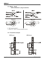
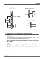
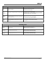
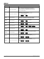
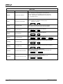
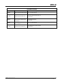
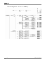
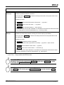
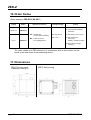
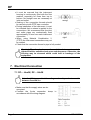
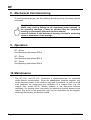
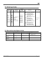
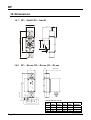
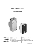
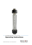
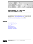
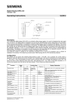
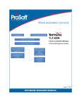
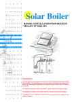
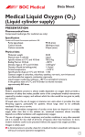
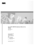
1
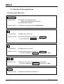
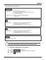
Operating Instructions
for
Counter Electronic
Model: ZED-Z
or DF-…ZLxxx
or Model-…ExxR
ZED-Z
1. Contents
1.
2.
3.
4.
5.
6.
Contents ........................................................................................................ 2
Note .............................................................................................................. 3
Instrument Inspection .................................................................................... 3
Regulation Use.............................................................................................. 3
Operating Principle........................................................................................ 4
Electrical Connection .................................................................................... 5
6.1 ZED-Z, DRB-…ExxR, DPE-…ExxR field housing and control panel
installation ............................................................................................ 5
6.2 DF-…ZLxxx, Model-…ExxR cable connection ................................. 5
6.3 Model-…ExxR cable connection + plug connection ......................... 6
6.4 Connection example ............................................................................ 6
7. Operation / Configuration / Adjustments ....................................................... 7
7.1 General ................................................................................................ 7
7.2 Function of the control keys ................................................................. 8
7.3 Character explanation for main menu .................................................. 9
7.4 General Settings ................................................................................ 10
7.5 Flow, analogue output and relay 1 ..................................................... 12
7.6 Relay 2 and volume counter .............................................................. 15
7.7 User alignment and Service-Settings ................................................. 18
7.8 Error report ........................................................................................ 21
8. Relay Functions .......................................................................................... 22
8.1 Switching characteristic limit value .................................................... 22
8.2 Switching characteristic window ........................................................ 22
9. Technical Information .................................................................................. 23
10. Order Codes ............................................................................................... 24
11. Dimensions ................................................................................................. 24
12. Declaration of Conformance ....................................................................... 25
Manufactured and sold by:
Kobold Messring GmbH
Nordring 22-24
D-65719 Hofheim
Tel.: +49(0)6192-2990
Fax: +49(0)6192-23398
E-Mail: [email protected]
Internet: www.kobold.com
page 2
ZED-Z K06/0813
ZED-Z
2. Note
Please read these operating instructions before unpacking and putting the unit
into operation. Follow the instructions precisely as described herein.
The devices are only to be used, maintained and serviced by persons familiar
with these operating instructions and in accordance with local regulations
applying to Health & Safety and prevention of accidents.
When used in machines, the measuring unit should be used only when the
machines fulfil the EWG-machine guidelines.
3. Instrument Inspection
Instruments are inspected before shipping and sent out in perfect condition.
Should damage to a device be visible, we recommend a thorough inspection of
the delivery packaging. In case of damage, please inform your parcel service /
forwarding agent immediately, since they are responsible for damages during
transit.
Scope of delivery:
The standard delivery includes:
• Counter Electronic model: ZED-Z or flowmeter incl. Counter Electronic
• Operating Instructions
4. Regulation Use
Any use of the Counter Electronic, model: ZED-Z, which exceeds the
manufacturer’s specification may invalidate its warranty. Therefore, any resulting
damage is not the responsibility of the manufacturer. The user assumes all risk
for such usage.
ZED-Z K06/0813
page 3
ZED-Z
5. Operating Principle
The evaluation unit changes the frequency signal of the pickup into a 3(4)-digit
flow reading with selectable measurement unit (top display line), and into a
scalable analogue signal. The flow quantity is added up in a part quantity meter
and a total quantity meter and then displayed in the bottom line of the screen.
The quantity meter’s units of measurement are selectable.
The two relays with floating output changeover contacts continuously monitor if
the freely adjustable limits are exceeded or fallen short of. Here, it is possible to
choose between threshold value and window monitoring.
Switching point, hysteresis, a window point, and switch on or off delay can be
set separately for each relay. The switching points can also be set directly by
using the control keys without having to change over into the menu.
Alternatively, it is also possible to monitor the quantity meter to see if it is
exceeded. A red LED indicates with the switching status.
The analogue output is optionally available as current output with 0(4)...20 mA
or as voltage output with 0...10 V. The Parameter names can be shown in the
menu in German or English. If used where the flow readings change rapidly, the
display can be pacified and the analogue reading averaged by switching on
some software. When using analogue output 0 – 10 V the customer must put a
jumper between the terminals 7 and 8.
A MIN/MAX reading memory determines the extreme readings of the flow. The
display of the readings and the resetting are achieved by using the keys without
having to change into the menu. Resetting by using the keys can also be
blocked. If the maximum set flow (exceeded range) is exceeded, it will be shown
on the display.
The set parameters can be protected against unauthorized alteration by using a
password function.
Range of functions
Quantity meter and flow meter with digital display, switch and analogue output:
• Measurement and display total, part and flow quantities
• Free scaling using input of frequency and measured value
• Control input for part quantity reset
• 2 switching outputs, freely programmable as flow monitor or for monitoring
the part and total quantity
• Analogue output 0(4)-20 mA oder 0-10 V
• MIN/MAX memory
page 4
ZED-Z K06/0813
ZED-Z
6. Electrical Connection
6.1 ZED-Z, DRB-…ExxR, DPE-…ExxR
field housing and control panel installation
*) Don’t connect terminal!
**) Reset TM – GND => reset part quantity counter
6.2 DF-…ZLxxx, Model-…ExxR
cable connection
Wire number
1
2
3
4
5
6
7
8
9
10
ZED-Counter electronics
+24 VDC
GND
4-20 mA / 0-10 V
GND
d.c. *)
Reset TM
Relay S1 N/O
Relay S1 COM
Relay S2 N/O
Relay S2 COM
**
*) Don’t connect terminal!
**) Reset TM – GND => reset part quantity counter
ZED-Z K06/0813
page 5
ZED-Z
6.3 Model-…ExxR
cable connection + plug connection
*) Don’t connect contact !
**) Reset TM – GND => reset part quantity counter
6.4 Connection example
PNP-Sensor
page 6
NPN-Sensor
ZED-Z K06/0813
ZED-Z
NAMUR-Sensor
Analogausgang
analogue output0-10
0-10VV
GND
0-10 V
9
8
7
V
analogue
output 0-20 mA
Analogausgang
10
GND 9
8
0-20 mA 7
7. Operation / Configuration / Adjustments
7.1 General
Only the menu items which lines are marked in the selection matrix in grey
colour, are available in the respective instrument version.
Italic written values are blinking in the display, if they have been chosen
for any input.
The parameter can only be changed, if the security code has been
entered correctly! The message „locked“ will appear if the input has
not been activated.
ZED-Z K06/0813
page 7
ZED-Z
7.2 Function of the control keys
Operating mode >Measure< :
PGM/ENTER
- Press briefly:
Æ a) Display total quantity, then
Display corresponding scale unit or
Æ b) Reset status reports.
- Press for 3 sec: Æ Switch to operating mode >Parameterize<.
▼
- - Press briefly:
Æ Display min. flow value.
- Press for 3 sec: Æ Enter switching point for Relay S1 s1SPoint
(only if parameter SPdirect is set to “yes”).
.
▲
- - Press briefly:
Æ Display max. flow value.
- Press for 3 sec: Æ Enter switching point for Relay S2 s2SPoint
(only when parameter SPdirect is switched to “yes”).
▼ + ▲
Press for 3 sec:
Æ Sets min. and max. value memory to flow value
(only when parameter fMMReDir is switched to “yes”).
RESET
- Press for 3 sec: Æ Sets the part quantity counter to 0.
page 8
ZED-Z K06/0813
ZED-Z
Operating mode >Parameterize<:
PGM/ENTER
- Press briefly:
Æ a) Open parameter group or
Æ b) Change parameter (go lower in menu level) or
Æ c) Adopt value input.
- Press for 3 sec: Æ Abort input (ESC) and go back one
menu level.
▼
- Press briefly:
Æ a) Select parameter group or parameter or
Æ b) Reduce selected number by 1 or
Æ c) Select list value (e.g.... L/m, L/h, m3/m, ...).
▲
- Press briefly:
Æ a) Select parameter group or parameter or
Æ b) Increase selected number by 1 or
Æ c) Select list value (e.g.... m3/m, L/h, L/m, ...).
RESET
- No function in this mode.
Note: If no button is pressed for 20 seconds during parameterising, the
instrument automatically switches back into >measuring< mode.
7.3 Character explanation for main menu
(e)
(E)
(▼ )
(▲ )
-
Button
Button
Button
Button
ZED-Z K06/0813
PGM/ENTER press shortly.
PGM/ENTER press and hold for approx. 3 seconds.
▼ press shortly.
▲ press shortly.
page 9
ZED-Z
7.4 General Settings
page 10
ZED-Z K06/0813
ZED-Z
GENERAL SETTINGS
Menu Item
Parameter / Function
Explanation / Values / Other
Language
Select menu language
German or English
fUnitFS *
Measuring unit for flow
measurement
mL/s, mL/m, L/s, L/m, L/h, m /m, m /h,
GPM, GPH, UU/s, UU/m, UU/h
fValueFS *
Maximum measuring range value
for flow measurement
Range = 0,00...99,9..._100...9999
fMinVal *
Minimum measuring range value
for flow measurement
fPls/rev*
Impulse per sensor wheel
revolution
Number of impulses per revolution of the sensor wheel or the like
Necessary for long-term period averaging if the readings per revolution vary.
The function is switched off when the input value is 1.
fJumpVD*
Flow switch value for attenuation
cut-off
Value in %, basis is fValueFS and fUnitFS.
Attenuation does not function if the switch value is 0%.
fOverflV *
Flow overflow value (overflow)
Value in %, basis is fValueFS and fUnitFS.
If exceeded, an M100 report is generated and faded in, alternating
with the flow indicator.
The report is saved and can be reset by briefly pressing the
PGM key.
fFactor
Select pulse ration
Selection of works calibration or user calibration.
(only for devices Model DF-...ZLxxx and Model-...ExxR)
UserUnit.
Special volume unit
Customer-specific special unit UU.
The value entered corresponds to the number of litres of the special unit, e.g.
in the case of the unit Barrel the factor would for example be 115.6271.
SPdirect
Activation of direct input switching
point
3
3
Basis is fValueFS and fUnitFS
If the level drops below this, the flow indicator goes to 0.
yes: Direct input of switching points s1SPoint and
s2SPoint is possible using the keys (default).
no: The switching points can only be set in the menu .
*)
Only for ZED devices: Device-specific parameter, is only visible after activation in the SecCode menu item in the SERVICE
menu group, and can be changed.
ZED-Z K06/0813
page 11
ZED-Z
7.5 Flow, analogue output and relay 1
page 12
ZED-Z K06/0813
ZED-Z
FLOW
Menu Item
Parameter / Function
Explanation / Values / Other
3
Unit of flow indicator
fUnit
fDamping
fMMReDir
Attenuation of reading fluctuations in the flow indicator
Resets the Min/Max flow value directly using the keys,
without using the menu
3
mL/s, mL/m, L/s, L/m, L/h, m /m, m /h,
GPM, GPH, UU/s, UU/m, UU/h
The attenuation pacifies the flow indicator.
The attenuation value is the approximate equivalent of the setting time
of the display value to c. 90% of a measured value jump in seconds.
(Parameter is blocked at DF-...ZLxxx devices).
yes: direct resetting of the Min/Max value memory by simultaneously
pressing (3 sec) the (+) and (-) keys (default).
no: memory reset only possible with fMMRST.
fMMRST
Resets the Min/Max flow value memory of the flow
indicator
yes: Resets Min / Max value memory for the flow
no: No action.
ANALOGUE OUTPUT
Parameter / Function
Menu Item
Explanation / Values / Other
aLIFE 0
Select Life Zero
Offset at power output: 0 mA or 4 mA
at 0-10 V ≙ 0 mA → 0 V and 4 mA → 2 V
aLowFlow
Flow reading at 0/4 mA or 0/2 V
Lower flow reading of gauged output range,
value has the same unit as the flow indicator
aHighFlo
Flow reading at 20 mA or 10 V
Upper flow reading of gauged output range,
value has the same unit as the flow indicator
ZED-Z K06/0813
page 13
ZED-Z
RELAY S1
Menu Item
s1Funct.
Parameter / Function
Relay1 Function selection
Explanation / Values / Other
Flow.: Monitoring of an adjustable flow value (s1SPoint).
TA Limit: Monitoring of an adjustable total volume (s1TA-Lim).
PA-Limit: Monitoring of an adjustable part volume (s1PA-Lim).
see Æ 8.0 Relay functions
s1Char.
Relay1 Switch characteristic
Limit: Monitoring a reading (s1SPoint).
Window: Monitoring an adjustable measuring range
(s1SPoint...s1Fpunkt).
(only if s1Funct. is set to Flow)
s1Logic
Relay1 Switch logic
normal: Relay 1 activated when the limit value is exceeded.
invers: Relay 1 drops out when the limit value is exceeded.
s1SPoint
Relay1 Switchpoint
Reading is in the same units as the flow indicator.
(only if s1Funct. is set to Flow)
s1Hyste
Relay1 Hysteresis
Reading is in the same units as the flow indicator.
(only if s1Funct. is set to Flow)
s1FPoint
Relay1 Windowpoint
Reading is in the same units as the flow indicator.
(only if s1Funct. is set to Flow und s1Char. auf Window )
s1SDelay
Relay1 Switch delay
Delays the switching of the relay when the limit value is exceeded.
Range:_ 0,0...99,9 sec
(only if s1Funct. is set to Flow)
s1RDelay
Relay1 Reset delay
Delays the switching of the relay when the limit value is undershot.
Range:_ 0,0...99,9 sec
(only if s1Funct. is set to Flow)
Relay1 Part volume limit value
Limit value for monitoring the part volume counter.
Reading is in the same units as the part volume unit (PA-Unit.) in
counter menu group.
(only if s1Funct. Is set to GM Limit )
s1PA-Lim
s1TA-Lim
page 14
Relay1 Total volume limit value
Limit value for monitoring the total volume counter.
Reading is in the same units as the total volume unit (TA-Unit) in
counter menu group.
(only if s1Funct. Is set to TA Limit )
ZED-Z K06/0813
ZED-Z
7.6 Relay 2 and volume counter
ZED-Z K06/0813
page 15
ZED-Z
RELAY S2
Menu Item
s2Funct.
Parameter / Function
Relay2 Function selection
Explanation / Values / Other
Flow : Monitoring of an adjustable flow value (s2SPoint).
TA-Limit: Monitoring of an adjustable total volume (s2TA-Lim).
PA-Limit: Monitoring of an adjustable part volume (s2PA-Lim).
see Æ 8.0 Relay functions
s2Char.
Relay2 Switch characteristic
Limit: Monitoring a reading (s2SPoint).
Window: Monitoring an adjustable measuring range
(s2SPoint...s12punkt).
(only if s2Funct. is set to Flow)
s2Logic
Relay2 Switch logic
normal: Relay 2 activated when the limit value is exceeded.
invers: Relay 2 drops out when the limit value is exceeded.
s2SPoint
Relay2 Switchpoint
Reading is in the same units as the flow indicator.
(only if s2Funct. is set to Flow)
s2Hyste
Relay2 Hysteresis
Reading is in the same units as the flow indicator.
(only if s2Funct. is set to Flow)
s2FPoint
Relay2 Windowpoint
Reading is in the same units as the flow indicator.
(only if s2Funct. is set to Flow)and s2Char. Is set to Window )
s2SDelay
Relay2 Switch delay
Delays the switching of the relay when the limit value is exceeded.
Range:_ 0,0...99,9 sec
(only if s2Funct. is set to Flow)
s2RDelay
Relay2 Reset delay
s2PA-Lim
s2TA-Lim
page 16
Delays the switching of the relay when the limit value is undershot.
Range:_ 0,0...99,9 sec
(only if s2Funct. is set to Flow)
Relay2 Part volume limit value
Limit for monitoring the part volume counter.
Reading is in the same units as the part volume units (PA-Unit.)
in the counter menu group.
(only if s2Funct. Is set to PA-Limit )
Relay2 Total volume limit value
Limit for monitoring the total volume counter.
Reading is in the same units as the total volume units
(TA-Unit) in the counter menu group.
(only if s2Funct. Is set to TA-Limit )
ZED-Z K06/0813
ZED-Z
VOLUME COUNTER
Menu Item
Parameter / Function
Explanation / Values / Other
3
PA-Unit.
Units on the part volume indicator
mL, L, m , gal, mgal, UU
PA
Set part volume counter to 0
yes: Part volume counter is set to 0
no: No action
PA0dirct
0-setting option of the part
volume counter released using
the reset key
yes: Released (default)
no: Blocked
TA-Unit
Measuring units on the total
volume indicator
mL, L, m , gal, mgal, UU
TA
Set total volume counter to 0
yes: Total volume counter is set to 0
no: No action
=0?
=0?
ZED-Z K06/0813
3
page 17
ZED-Z
7.7 User alignment and Service-Settings
page 18
ZED-Z K06/0813
ZED-Z
USER CALIBRATION
Menu Item
CAL Freq*
Function / Description
Calibrate by entering frequency and flow.
In the menu item CAL Freq the bottom line always shows the current pulse value of the
User calibration.
Calibration process:
a) FlowVal Enter nominal flow value of the sensor. > (e) press >
b) FlowUnit Enter unit for flow value. > (e) press >
c) Freq.Val. Enter nominal frequency > finish with (e).
The new pulse value of the User calibration is calculated from these three values and saved
as user calibration for the flow measurement, e.g. 20.2757 pls./litre.
CAL Vol.
Calibration process using impulse counting and volume input (cc procedure).
In the menu item CAL Vol. the bottom line always shows the current pulse value of the
User calibration.
Calibration process:
a) PulseCnt measures number of impulses
(e) press > start counter (impulses are counted) > (e) press > stops counter.
b) Vol.Val Enter measured volume value > (e) press.
c) Vol.Unit Enter unit for volume value > finish with (e).
The pulse value of the User calibration is calculated from these three values and is saved
as the user calibration for the flow measurement, e.g. 3900,5 pls./L.
*) CAL Freq – Only possible with ZED devices.
Note: With ZED devices it is necessary to enable the device-specific
parameter input in the menu Item SecCode in the menu SERVICE in order
to activate the USER-ABGLEICH function.
Note: If the new pulse ratio will be used for measurement, than the menu
item fFaktor in the menu group General Settings must be setted to USER
calibration.
ZED-Z K06/0813
page 19
ZED-Z
SERVICE
Menu Item
SecCode
Input
Function
Enter security code
Explanation / Values / Other
Input of 4-digit security code
and enablement of the parameter change.
The following passwords have been defined:
3461 – General menu release
6571 – Activates the device-specific
parameters (only ZED und Modeldevices)
SecCode
change
Change security code
Define or change security code for the first time
or change.
If no code ( = 0000) has been set, then the
parameter values set are unsecured!
Save Prm
Save parameter record
Save current settings
Load Prm
Load parameter record
Restore saved settings (reload).
Restore
Default
Reset to works default settings
Load initial setting with password 2541.
page 20
The function is blocked when the sensor has
been factory-calibrated (only Model-devices).
ZED-Z K06/0813
ZED-Z
7.8 Error report
Error code
E102
Reason
UU User unit may not be ≤ 0
Reset
Correct parameter
E142
Distance between upper and lower analogue
value too small (based on the actual flow)
Correct parameter
E143
Correct parameter
E162
Distance between upper and lower analogue
value too small (based on the dosing amount)
Value is greater than maximum measuring
range value.
Hysteresis too large
Correct parameter
E 163
E242
Window point is lower than switching point.
Frequency must be between 0,2 and 2000 Hz
Correct parameter
Correct parameter
E245
Calculated pulse value out of valid range
Correct parameter
M100
Overflow
Acknowledge with PGM button
####
Value does not fit in the display
Choose suitable measuring unit
E 161
ZED-Z K06/0813
Correct parameter
page 21
ZED-Z
8. Relay Functions
8.1 Switching characteristic limit value
MV
sxSPoint
sxSPoint
- sxHyste
REL Sx
8.2 Switching characteristic window
MV
sxFPoint
+ sxHyste
sxFPoint
sxSPoint
sxSPoint
- sxHyste
REL Sx
page 22
ZED-Z K06/0813
ZED-Z
9. Technical Information
Display:
Display rate:
Flow display:
Flow units:
Quantity meter:
Quantity units:
Measurement input:
Parameter input:
Parameter protection:
Control elements:
Custom. comparison:
Control input:
Relay outputs:
Voltage supply:
Analogue output:
Apparent power:
Ambient temp.:
Dimensions:
Aperture size:
Casing material:
Protection type:
Mounting:
Connection:
Weight:
ZED-Z K06/0813
2 x 8-digit alphanumeric,
LCD module, illuminated
1 s-1
3- or 4-digit
(XX.X, X.XX or XXXX)
mL/s, mL/m, L/s, L/m, L/h, m3/m,
m3/h, GPM, GPH, user unit per h/min/s
selectable
8-digit
mL, L, m3, gal, mgal, user unit selectable
0.2...2000 Hz (5...24 VDC), TTL, PNP, NPN,
Namur
menu controlled, German or English
4-digit password
4 keys
by entering the frequency and measured value
Or in the Teach-In procedure (level calibration)
reset function
2 x changer
max. 250 VAC/DC
max. 5 A / 1000 VA
24 VDC ± 20 %, approx. 80 mA or
90...250 VAC / max. 3 VA
0(4)-20 mA
Load: max. 500 Ω (300 Ω at AC-Supply)
or 0-10 V (Load: > 100kΩ)
15 V (at 24 VDC) / max. 50 mA
12 V (AC-supply) / max. 50 mA
-20...+70 °C
96 x 96 x 109 mm (LxWxD) incl.
screw clamp (control panel installation)
117 x 117 x 127 mm (LxWxD) (field casing)
92+0.8 x 92+0.8 mm (control panel installation)
fibreglass reinforced Noryl,
(control panel installation)
powder coated aluminium/PA 66 (field casing)
IP 40 on front
clamp IP 00 (control panel installation)
IP 65 (field casing)
mounting clip Form B (DIN 43 835)
(control panel installation)
wall and pipe mounting (field casing)
plug-in terminal strip (control panel installation)
cable connection (field casing)
approx. 360 g (control panel installat.)
approx. 1240 g (field casing)
page 23
ZED-Z
10. Order Codes
(Order example: ZED-ZF10 KS 4R P)
Supply
Model
90-250 VAC
ZED-ZF10
Electrical connection
ZED-ZF13
Casing
P = control panel installation
96x96 mm
KS = terminal strip
(control panel installation)
24 VDC
Analogue output
MS = cable connection
M 18 (Feldgehäuse)
4R = 0(A)-20 mA
1 R = 0-10 V
F = field casing 116 x116 mm
S = field casing with
wall mount,
infinitely variable pivotable
R = field casing with pipe
mounting
The order details of a ZED electronic in combination with a flow sensor can be
found in the data sheet of the measuring device.
11. Dimensions
ZED-Z Control panel
installation (casing P)
page 24
ZED-Z field housing
ZED-Z K06/0813
ZED-Z
12. Declaration of Conformance
We, KOBOLD Messring GmbH, Hofheim-Ts, Germany, declare under our sole
responsibility that the product:
Counter Electronic Model: ZED-Z
to which this declaration relates is in conformity with the standards noted below:
EN 61326-1
2006-10
Electrical equipment for control and instrumentation technology and laboratory
use – EMC-requirements (industrial area)
DIN EN 61010-1
2002-08
Safety requirements for electrical
instruments.
measuring-,
control-
and
laboratory
EN 60529, DIN VDE 0470-1
1992-11
Protection type housing (IP-Code)
Also the following EWG guidelines are fulfilled:
2004/108 EC
2006/95 EC
EMC Directive
Low Voltage Directive
Hofheim, 12. Nov. 2007
H. Peters
General Manager
ZED-Z K06/0813
M. Wenzel
Proxy Holder
page 25
Operating Instructions
for
Flow Monitor
Model: DF-...Hxx3K
DF-...IHx3K
DF-...KLxxx
DF-...DLxxx
DF-...ZLxxx
DF
1. Contents
1.
2.
3.
4.
5.
6.
7.
Contents ........................................................................................................ 2
Note .............................................................................................................. 3
Instrument Inspection .................................................................................... 3
Regulation Use.............................................................................................. 4
Operating Principle........................................................................................ 5
Mechanical Connection ................................................................................. 5
Electrical Connection .................................................................................... 6
7.1. DF-…Hxx3K, DF-…IHx3K ................................................................... 6
7.2. DF-…KLxxx, DF-…ZLxxx, DF-…DLxxx ............................................... 7
8. Mechanical Commissioning........................................................................... 8
9. Operation ...................................................................................................... 8
10. Maintenance ................................................................................................. 8
11. Technical Information .................................................................................... 9
12. Ordering Codes ........................................................................................... 11
13. Recommended Spare Parts ........................................................................ 11
14. Dimensions ................................................................................................. 12
14.1. DF-…IHx3K, DF-…Hxx3K ................................................................. 12
14.2. DF-…KLxxx, DF-…ZLxxx, DF-…DLxxx ............................................. 12
15. Declaration of Conformance ....................................................................... 13
Manufactured and sold by:
Kobold Messring GmbH
Nordring 22-24
D-65719 Hofheim
Tel.: +49(0)6192-2990
Fax: +49(0)6192-23398
E-Mail: [email protected]
Internet: www.kobold.com
Page 2
DF K02/0709
DF
2. Note
Please read these operating instructions before unpacking and putting the unit
into operation. Follow the instructions precisely as described herein.
The devices are only to be used, maintained and serviced by persons familiar
with these operating instructions and in accordance with local regulations
applying to Health & Safety and prevention of accidents.
When used in machines, the measuring unit should be used only when the
machines fulfil the EWG-machine guidelines.
PED 97/23/EG
In acc. with Article 3 Paragraph (3), "Sound Engineering Practice", of the
PED 97/23/EC no CE mark.
Pipe
Table 8
Group 1
dangerous fluids
Table 9
Group 2
no dangerous fluids
Art. 3, § 3
Art. 3, § 3
DF-xxGR32../DF-xxGR40
not deliverable
Art. 3, § 3
DF-xxHR32../DF-xxHR40..
Kat. II
Art. 3, § 3
DF-xxHF50..
Kat II
Art. 3, § 3
All DF-models except
DF-xxG(H)R32
DF-xxG(H)R40
3. Instrument Inspection
Instruments are inspected before shipping and sent out in perfect condition.
Should damage to a device be visible, we recommend a thorough inspection of
the delivery packaging. In case of damage, please inform your parcel service /
forwarding agent immediately, since they are responsible for damages during
transit.
Scope of delivery:
The standard delivery includes:
• Sensor housing with mounted connection box or electronics
• Operating Instructions
DF K02/0709
Page 3
DF
4. Regulation Use
The units of model DF are used for measurement of liquid flow. Only low viscosity
fluids which are chemically compatible with the materials used in the sensor
housing are allowed to be measured. If using higher viscosity media, large
measuring errors can occur. Long threads can lead to the seizure of the rotor.
Likewise, ferritic particles can build up on the rotating vane and lead to faulty
operation or destruction of the rotor. If in doubt, please contact the supplier.
Material Combinations
High-pressure
version
Standard version
Material
combination
I
II
IIB1)
III
IV1)
VI1)
VII1)
Order code
..A..
..B..
..C..
..D..
..E..
..G..
Pipe thread
flange
Pipe
thread
..H..
Pipe
thread
flange
Connection
Pipe thread Pipe thread Pipe thread Pipe thread
types
Brass
Brass
Brass
-
Brass
nickelplated
Brass
nickelplated
Brass
nickelplated
-
NBR
FPM
FPM
NBR
FPM
NBR
FPM
POM
PTFE
PTFE
POM
PTFE
POM
PTFE
Case
Trogamide Polysulfone
PolyBrass
propylene nickel-plated
St.St.4)
Cover
Trogamide Polysulfone
PolyPolysulfone
propylene
Polysulfone
PolyBrass
propylene nickel-plated
St.St.4)
Locking pins
Brass
nickelplated
Brass
O-rings
Vane
Connection
3)
4)
Axle
St.St.
Bearing3)
PTFE
Screen
2)
PTFE
St.St.4)
4)
St.St.
PTFE
2)
PTFE
4)
ceramics
St.St.
PTFE
PTFE
2)
PTFE
2)
PTFE
4)
St.St.
PTFE
2)
2)
-
St.St.4)
PTFE
PTFE2)
100 bar
100 bar flange
PN 40
10 bar
6 bar
16 bar
16 bar
Max.
operating
temperature
60 °C
80 °C
80 °C
80 °C
80 °C
Page 4
PTFE
St.St.4)
PTFE
10 bar
2) St. St. for model DF 0.5
St.St.
St.St.4)
PTFE
Max.
operating
pressure
1) Connection cannot be rotated
4)
St.St.4)
3) Special version upon request
80 °C
80 °C
4) St.St.1.4571
DF K02/0709
DF
5. Operating Principle
KOBOLD measuring sensors are available with pipe thread or flange
connections; standard or high-pressure versions are optional. The standard
version is delivered with a standard front cover from solid, transparent plastic,
which allows the flow to be optically inspected. The rotary motion of the shining
red vane can be clearly seen. Faults such as power failure or rotor blockage can
thus be quickly detected in situ. In addition to their use as measuring and
monitoring systems, the devices can also be used as flow indicators.
The standard front cover is replaced by a metal plate on the high-pressure
version (up to 100 bar with the threaded version). The devices can be installed in
any position. However, the flow must always be in the direction of the arrow, and
the front panel of the device must be arranged in the vertical plane. The fluidic
housing must be full with liquid. Additional inlet or outlet pipes are not required.
The large radial clearance between vane and housing wall renders the measuring
sensor insensitive to dirt. Depending on the version, the connection fittings can
be rotated and are bearing mounted. Switching electronics or vane front may be
rotated at will for ease of viewing (while in service).
The KOBOLD measuring sensors are also available without a compact electronic.
The linear flow proportional pulse signal provided by the sensor can be controlled
by customer own electronics. The customer is able to integrate the sensor directly
into the electronics with the OEM-version (implement EMC-immunity) and can
therefore save costs and material.
6. Mechanical Connection
Before installation
• Please make sure that the actual flow throughput matches the flow range of
the instrument. The flow range may be read from the label.
Warning! If the measuring range is exceeded by more than 20%,
bearing damage may occur.
• Please make sure that the allowable maximum operating pressure and
operating temperature of the instruments are not exceeded.
• Make sure that the electrical supply to the instrument conforms to the
equipment operating data (see label).
• Remove all transport packing and make sure that no packing material is left in
the instrument.
• The instrument may be installed in any position. However, the flow must
always take place in the direction of the arrow, while the front face of the
instrument must always be in the vertical plane.
DF K02/0709
Page 5
DF
• It must be ensured that the instrument
housing is continuously filled with the flow
medium, especially for flows from top to
bottom. No straight runs are necessary at
inlet and outlet.
wrong!
• Sealing of the connection threads should
be carried out with PTFE tape or similar.
• During installation of the instrument, it must
be checked that no stress is applied to the
connections. We recommend that the inlet
and outlet pipes are mechanically fixed
approximately 50 mm from each instrument
connection.
right!
• When using Material Combination V
(PTFE) the instrument connections may not
be rotated.
• Check that the connection thread to pipe is fully sealed.
Warning! The threaded connections of the instrument must be
tightened with a suitable sized open ended spanner. Otherwise, the
housing may be stressed which could lead to breakage of the
equipment.
7. Electrical Connection
7.1 DF-…Hxx3K, DF-…IHx3K
Attention! Make sure that the voltage value of your instrument is
between 5 and 24 VDC.
• Make sure that the supply wires are deenergised.
• Connect the 3-pole connection clamp
accordance with the wiring diagram.
Page 6
in
DF K02/0709
DF
Attention! Incorrect wiring will lead to damage of the unit’s
electronics.
7.2 DF-…KLxxx, DF-…ZLxxx, DF-…DLxxx
Attention! Make sure that the voltage value of your instrument is
24 VDC.
• Make sure that the supply wires are de-energised.
• Connect the wires in accordance with the wiring diagram.
Wire
number
1
2
3
4
5
6
7
8
9
10
ZED-…KLxxx
ZED-…ZLxxx
ZED-…DLxxx
+24 VDC
GND
4-20 mA
GND
d.c. *)
d.c. *)
relay S1 N/O
relay S1 COM
relay S2 N/O
relay S2 COM
+24 VDC
GND
4-20 mA
GND
d.c. *)
Reset TM *)
relay S1 N/O
relay S1 COM
relay S2 N/O
relay S2 COM
+24 VDC
GND
4-20 mA
GND
Ctrl 1 *)
Ctrl 2 *)
relay S1 N/O
relay S1 COM
relay S2 N/O
relay S2 COM
*) d.c. = Don’t connect wire!
Reset TM = Reset part quantity
Ctrl 1 -- GND => Start
Ctrl 2 -- GND => Stop
Ctrl 1 -- Ctrl 2 -- GND => Reset dosage
Attention! Incorrect wiring will lead to damage of the unit’s
electronics.
DF K02/0709
Page 7
DF
8. Mechanical Commissioning
To avoid pressure surges, the flow medium should be slowly introduced into the
instrument.
Attention! Pressure surges from solenoid valves, ball valves or
similar may result in damage to the instrument (water hammer). In
the operating condition it must be checked that the instrument
housing is continuously filled with the flow medium.
Large air bubbles in the instrument housing can lead to measuring
errors or destruction of the bearings.
9. Operation
DF-...KLxxx
See Operating Instructions ZED-K
DF-...ZLxxx
See Operating Instructions ZED-Z
DF-...DLxxx
See Operating Instructions ZED-D
10. Maintenance
The DF-..HN.. and DF-..HP.. instrument is maintenance-free for measured
media without contamination,. Since the paddlewheel contains magnets, any
ferritic particles present in the medium may lead to problems. In order to avoid
such problems, we recommend the installation of a magnet filter (e.g. the
magnet filter, model MF-R). Should cleaning of the instrument become
necessary, the housing cover may easily be removed to provide access to the
interior. Any work on the electronics may only be undertaken by the supplier;
otherwise the warranty will become invalid.
Page 8
DF K02/0709
DF
11. Technical Information
Measuring accuracy:
Medium temperature:
Protection type:
2.5% of f. s.
-20 to +80 °C (0…60 °C Material Comb.: I)
IP 65
Frequency output (OEM) no CE (DF-...IHO3K, DF-...IHP3K)
Power supply:
5-24 VDC
Supply current:
approx. 5 mA
Signal amplitude high:
approx. power supply
Signal amplitude low:
= 0.2 V
Output loss:
max. 2.5 mW
Electrical connection:
approx. 80 mm cable
Pulse output:
NPN, open collector, max. 15 mA,
not symmetric
Frequency output (DF-...Hxx3K)
Power supply:
Supply current:
Signal amplitude high:
Signal amplitude low:
Output loss:
Electrical connection:
Pulse output:
Special versions:
K-Electronics
Display:
Power supply:
Current consumption:
Electrical connection:
Analogue output:
Switching output:
Control elements:
Functions:
DF K02/0709
5-24 VDC
approx. 5 mA
approx. power supply
= 0.2 V
max. 2.5 mW
PC-connection box with cable connection
NPN or PNP, open collector, max. 15 mA,
not symmetric
high temperature version,
DIN-plug connection
double-spaced display, illuminated
flow value with selectable units
and bargraph display
24 VDC ±20 %
approx. 100 mA
10 wire cable connection
(0)4...20 mA selectable
Load: 0...500 Ω
or 0-10 VDC , Load: >100 kΩ
2 relays, max. 30 V / 2 A
via 3 keys
MIN/MAX memory, flow monitor,
language settings, password protection
Page 9
DF
Counter-Electronics
Display:
Quantity meter:
Power supply:
Current consumption:
Electrical connection:
Analogue output:
Relay outputs:
Control elements:
Functions:
Dosage-Electronics
Display:
Quantity meter:
Dosage:
Power supply:
Current consumption:
Electrical connection:
Analogue output:
Relay outputs:
Control elements:
Function:
Page 10
2 x 8-digit LCD module, illuminated,
total, part and flow quantity;
units of measurement selectable
8-digit
24 VDC ±20%
approx. 100 mA
10-pole cable connection
0(4)…20 mA selectable
Load: 0…500 Ω
or 0-10 VDC, Load: >100 kΩ
2 relays,
max. 30 V / 2 A
via 4 keys
Reset, MIN/MAX-memory,
flow monitor, monitoring of
part and total quantities,
language
2 x 8-digit LCD module, illuminated
dosage, total and flow quantity,
units of measurement are selectable
8-digit
5-digit
24 VDC ±20 %
approx. 100 mA
10-pole cable connection
0(4)...20 mA selectable
Load: 0...500 Ω
or 0...10 VDC, Load >100 kΩ
2 relays,
max. 30 V / 2 A
via 4 keys
dosage (relay S2),
start, stop, reset, fine dosage,
correction quantity, flow monitor,
total volume monitoring,
language
DF K02/0709
DF
12. Ordering Codes
Flow rate
L/min
0,08...0,5
0,2...1,4
0,2...2,5
0,3...2,6
0,4...5,0
0,25...6,0
0,5...12,0
1,00...12,5
1,00...24,0
2,00....48,0
2,5...60,0
5,00...120
40,0...160
Model
DF-05
DF-14
DF-25
DF-26
DF-50
DF-06
DF-12
DF-13
DF-24
DF-48
DF-60
DF-H2
DF-H6
Material
combination
(see transducer)
A = Trogamide/ brass
B = PSO/ VA
C = PP
D = Brass
E = St. St.
G = Brass, 100 bar
H = St. St., 100 bar
Connection
sizes
IG or flange
DIN 2527, PN40
R06 = G 1/8
R08 = G 1/4
R10 = G 3/8
R15 = G 1/2
R20 = G 3/4
R25 = G 1
R32 = G 1 1/4
R40 = G 1 1/2
F15 = DN 15
F25 = DN 25
F40 = DN 40
F50 = DN 50
Electronics
KLK3= Digital display, switching and
analogue output, 24 VDC
1.5 m cable connection
KLL3= Digital display, switching and
analogue output, 24 VDC
cable connection
(Please specify length in clear
text.)
ZLK3= Counter electronic,
digital display, 24 VDC,
1.5 m cable connection
ZLL3= Counter electronic, 24 VDC,
cable connection
(Please specify length in clear
text.)
DLK3= Dosing electronics, 24 VDC,
1.5 m cable connection
DLL3= Dosing electronic, 24 VDC,
cable connection (Please
specify length in clear text.)
Power supply
4= (0)4-20 mA
1= 0-10 V
* Flange connection for material combination stainless steel E or H only.
13. Recommended Spare Parts
Rotating vane
Axle / bearing
1.1) PTFE
2.1) St. St./PTFE
1.2) POM
1.3) PTFE with saphire bearing
2.2) Ceramic/PTFE 2.3) Saphire/Saphire
(only for 1.3)
3.2) Polysulfone
Cover for sensor
3.1) Trogamide
housing
Cover for electronic 4.1) NBR
housing.
O-rings
5.1) NBR
5.2) FPM
Please specify serial number when ordering spare parts.
DF K02/0709
Page 11
DF
14. Dimensions
14.1
DF-…IHx3K, DF-…Hxx3K
50
48
approx. 52
22.5
52
90
165 (flange: 200)
35
PG7
14.2
DF-…KLxxx, DF-…ZLxxx, DF-…DLxxx
48
22,5
approx.88,5
FLOW METER
FERNGEBER
90
165
ON
20 mA
flange =200
0(4) mA
d2
d4
K
D
Flange DIN 2501 PN 40
DN
15
25
40
50
Page 12
D
[mm]
95
115
150
165
K
[mm]
65
85
110
125
d4
[mm]
45
68
88
102
d2
[mm]
14
14
18
18
Screw
quantity
4
4
4
4
DF K02/0709
DF
15. Declaration of Conformance
We, KOBOLD-Messring GmbH, Hofheim-Ts, Germany, declare under our sole
responsibility that the product:
Flow Transmitter Model: DF-..HN.. and DF-..HP..
to which this declaration relates in conformity with the standards noted below:
EN 61000-6-4
Electromagnetic
environments
08-2002
compatibility
(EMC)
-
Emission
standard
for
industrial
EN 61000-4-2
12-2001
Electromagnetic compatibility (EMC) - Testing and measurement techniques Electrostatic discharge immunity test - Level 2
EN 61000-4-4
07-2005
Electromagnetic compatibility (EMC) - Testing and measurement techniques Electrical fast transient/burst immunity test – Level 2
EN 61010
08-2002
Safety requirements for electrical equipment for measuring control and laboratory
use
Also the following EWG guidelines are satisfied:
89/336 EWG
73/23 EWG
97/23/EC
PED
Category II, Table 8, pipe, liquids
Group 1 dangerous fluids
Module D, mark CE0098
notified body: Germanischer Lloyd Germany
Hofheim, 13. June 2008
H. Peters
General Manager
DF K02/0709
M. Wenzel
Proxy Holder
Page 13
DF
We, KOBOLD-Messring GmbH, Hofheim-Ts, Germany, declare under our sole
responsibility that the product:
Flow Meter
Flow Counter
Dosing Unit
Model: DF-…KLxxx
Model: DF-…ZLxxx
Model: DF-…DLxxx
to which this declaration relates in conformity with the standards noted below:
EN 61326: 1997
+A1: 1998
+A2: 2001
Electrical equipment for measurement, control and laboratory use
- Noise immunity: according EN 61326/A1 Amendment A table A.1
Criteria: according table 2, continuous not monitored operation
- Generic emission standard: according EN 61326/A1
Limit values: according table 4, equipment of class B
DIN EN 61010-11 1993
Safety requirements for electrical equipment for measuring control and laboratory
use
Also the following EEC guidelines are satisfied:
2004/108/EC
EMC Directive
2006/95/EC
Low Voltage Directive
97/23/EC
PED
Category II, Table 8, pipe, liquids
Group 1 dangerous fluids
Module D, mark CE0098
notified body: Germanischer Lloyd Germany
Hofheim, 13. June 2008
H. Peters
General Manager
Page 14
M. Wenzel
Proxy Holder
DF K02/0709