1
Installations- und Betriebsanleitung
Seite 2 - 8
Installation and Operating Instructions
Installation and Operating Instructions
Page 9 - 16
Side Channel Blower
VSC0055 – VSC2050
VSC_OI_001_en
Edition: 11/2009
All rights reserved
vacuvane vacuum technology gmbh
Amsterdamstr. 16
97424 Schweinfurt
Germany
Table of Contents
Preface .................................................................................................. 1
Technical Data .......................................................................................1
Product Description ................................................................................ 2
Use ..................................................................................................2
Principle of Operation ........................................................................ 2
Cooling .............................................................................................2
On/off Switch .................................................................................... 2
Safety ................................................................................................... 2
Intended Use .................................................................................... 2
Safety Notes ..................................................................................... 2
Noise Emission .................................................................................. 3
Transport .............................................................................................. 3
Transport in Packaging ...................................................................... 3
Transport without Packaging .............................................................. 3
Storage ................................................................................................. 3
Short-term Storage ............................................................................ 3
Conservation ..................................................................................... 3
Installation and Commissioning ................................................................ 4
Installation Prerequisites .................................................................... 4
Mounting Position and Space .............................................................. 4
Suction Connection/Gas Inlet .............................................................. 4
Gas Discharge ................................................................................... 4
Pressure Connection .......................................................................... 5
Electrical Connection / Controls ........................................................... 5
Controlling Pressure/Flow ................................................................... 5
Installation ............................................................................................ 5
Mounting .......................................................................................... 5
Connecting Electrically ....................................................................... 5
Connection Scheme Alternating Current Motor ................................ 5
Connection Scheme Three-Phase Motor .......................................... 6
Connecting Lines/Pipes ...................................................................... 6
Recording of Operational Parameters .................................................. 6
Operation Notes ................................................................................ 6
Use ............................................................................................. 6
Maintenance ..........................................................................................7
Maintenance Schedule ....................................................................... 7
Monthly: ...................................................................................... 7
Every 6 Months: ........................................................................... 7
Every Year: .................................................................................. 7
Overhaul ............................................................................................... 8
Removal from Service ............................................................................. 8
Temporary Removal from Service............................................................. 8
Recommissioning .............................................................................. 8
Dismantling and Disposal ................................................................... 8
Spare Parts ............................................................................................ 8
Preface
These operating instructions contain information for
•
product description,
•
safety,
•
transport,
•
storage,
•
installation and commissioning,
•
maintenance,
•
overhaul,
•
troubleshooting and
•
spare parts
of the side channel blower.
For the purpose of these instructions, "handling" the side channel blower
means the transport, storage, installation, commissioning, influence on
operating conditions, maintenance, troubleshooting and overhaul of the
side channel blower.
Prior to handling the side channel blower these operating
instructions shall be read and understood. If anything remains to
be clarified please contact your Vacuvane representative!
Keep these operating instructions and, if applicable, other
pertinent operating instructions available on site.
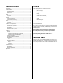
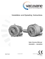
Technical Data
Motor connection parameters, nominal speeds and allowed differential
pressures are given on the nameplate of the side channel blower. More
technical data, available sizes, versions and accessories are given in the
current sales programme. In case of further questions please contact your
vacuvane representative!
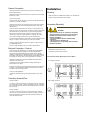
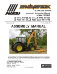
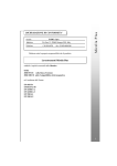
b
a
c
a
b
c
d
e
Directional arrows
Terminal box
Nameplate
Gas discharge / pressure connection
Gas inlet / suction connection
a
d
e
Product Description
Use
Cooling
The side channel blower is cooled by
- radiation of heat from the surface of the side channel blower
The side channel blower is intended for
- the air flow from the fan wheel of the drive motor
- the suction
- the process gas
- the compression
of
- air and other dry, non-aggressive, non-toxic and non-explosive gases
Conveying media with a higher density than air leads to an increased
thermal and mechanical load on the side channel blower and is permissible
only after prior consultation with vacuvane.
The gas shall be free from vapours that would condensate under the
temperature and pressure conditions inside the side channel blower.
The side channel blower is intended for the placement in a non-potentially
explosive environment.
The side channel blower is suitable for continuous operation, provided that
the housing can transmit heat to the environment unobstructedly and a
certain minimum gas transfer is warranted. If there is a risk that the side
channel blower may be operated against a closed inlet or outlet for more
than a few seconds, a vacuum or pressure relief valve, respectively, shall
be provided. Frequent switching on and off leads to increased coil
temperatures. In case of doubt seek advice from your vacuvane
representative!
The nominal value (=reference value for performance data) for the
temperature of the process gas is 15°C. The max. allowed temperature of
the inlet gas is 40 "C.
The nominal value for the ambient temperature is 25°C. The min. allowed
ambient temperature is -30°C. The max. allowed ambient temperature is
40°C.
Binding data with regard to the allowed differential pressure are to be read
from the nameplate (value with negative sign ("-") for vacuum operation,
value without sign for pressure operation). The data is valid for ambient
temperatures up to 25°C and location altitudes up to 1000 m above sea
level. Higher ambient temperatures reduce the allowed differential
pressures by up to 10 percent at 40°C. In case of placement in altitudes
beyond 1000 m above sea level the allowed differential pressure shall be
agreed upon with Vacuvane.
The maximum allowed pressure on the pressure connection (d) is
2 bar abs. By means of process control and/or pressure relief valves it
must be made sure that the maximum allowed pressure will not be
exceeded.
On/off Switch
The side channel blower comes without on/off switch. The control of the
side channel blower is to be provided in the course of installation.
Safety
Intended Use
DEFINITION: For the purpose of these instructions, "handling" the side
channel blower means the transport, storage, installation, commissioning,
influence on operating conditions, maintenance, troubleshooting and
overhaul of the side channel blower.
The side channel blower is intended for industrial use. It shall be handled
only by qualified personnel.
The allowed media and operational limits according to the
"Product Description" and the "Installation Prerequisites" of the
side channel blower shall be observed both by the manufacturer
of the machinery into which the side channel blower is to be
incorporated and by the operator.
The maintenance instructions shall be observed.
Prior to handling the side channel blower these operating
instructions shall be read and understood. If anything remains to
be clarified please contact your Vacuvane representative!
Safety Notes
The side channel blower has been designed and manufactured according to the state-of-the-art. Nevertheless, residual risks may remain.
These operating instructions inform about potential hazards where appropriate. Safety notes are tagged with one of the keywords DANGER,
WARNING and CAUTION as follows:
Principle of Operation
The side channel blower works on the impulse principle, i.e. kinetic energy
is transferred from the rotor to the conveyed medium and then is
converted into pressure.
DANGER
Disregard of this safety note will always lead to accidents
with fatal or serious injuries.
For the two stage version:
2 stages, both working on the principle described above, are installed in
line in order to achieve a better ultimate/differential pressure.
WARNING
The side channel blower compresses the inlet gas absolutely oil-free. A
lubrication of the pump chamber is neither necessary nor allowed.
Disregard of this safety note may lead to accidents with
fatal
or serious injuries.
CAUTION
CAUTION
Disregard of this safety note may lead to accidents with minor
injuries ine
Missachtung
dieses Sicherheitshinweises kann zu
injuries
or property
danmage.
Do not walk, stand or work under suspended loads.
• Attach lifting gear securely to the eyebolt on the cylinder
• Attach the lifting gear to a crane hook with safety latch
Noise Emission
• Lift the side channel blower with a crane
In case the side channel blower was bolted to a pallet or a base plate:
• Remove the stud bolts from the rubber feet
CAUTION
Depending on the construction size the side channel blower may emit
noise of high intensity.
Storage
Depending on the operating state the side channel blower may emit
noise in a narrow band.
Short-term Storage
Risk of damage to the hearing.
Persons staying in the vicinity of a non noise insulated side channel
blower over extended periods shall wear ear protection.
• Make sure that the suction connection/gas inlet and the gas discharge/pressure connection are closed (leave the provided plugs in)
• Store the side channel blower
- if possible in original packaging,
- indoors,
- dry,
- dust free and
Transport
Transport in Packaging
Side channel blowers individually packed in cardboard boxes can be
carried by hand.
Packed on a pallet the side channel blower is to be transported with a
forklift.
Transport without Packaging
In case the side channel blower is packed in a cardboard box with inflated
cushions:
• Remove the inflated cushions from the box
In case the side channel blower is in a cardboard box cushioned with
rolled corrugated cardboard:
• Remove the corrugated cardboard from the box
In case the side channel blower is laid in foam:
• Remove the foam
- vibration free
Conservation
In case of adverse ambient conditions (e.g. aggressive atmosphere, frequent temperature changes) conserve the side channel blower immediately. In case of favourable ambient conditions conserve the side channel
blower if a storage of more than 3 months is scheduled.
• Make sure that all ports are firmly closed; seal all ports that are not
sealed with PTFE-tape, gaskets or o-rings with adhesive tape
NOTE: VCI stands for "volatile corrosion inhibitor". VCI-products (film,
paper, cardboard, foam) evaporate a substance that condenses in molecular thickness on the packed good and by its electro-chemical properties
effectively suppresses corrosion on metallic surfaces. However, VCIproducts may attack the surfaces of plastics and elastomers. Seek advice
from your local packaging dealer! vacuvane uses CORTEC VCI 126 R film
for the overseas packaging of large equipment.
• Wrap the side channel blower in VCI film
• Store the side channel blower
- if possible in original packing,
- indoors,
In case the side channel blower is bolted to a pallet or a base plate:
• Remove the bolting between the side channel blower and the pallet/base
plate
- dry,
- dust free and
- vibration free.
In case the side channel blower is fastened to the pallet by means of
tightening straps:
For commissioning after conservation:
• Remove the tightening straps
• Make sure that all remains of adhesive tape are removed from the ports
In case the side channel blower weighs less than 20 kg and comes without
eyebolts for the attachment of lifting gear:
• Commission the side channel blower as described in the chapter
"Installation and Commissioning"
Version without handle:
• Grasp the side channel blower with both hands
Version with handle:
• Carry the side channel blower using the handle
In case the side channel blower comes with eyebolts for the attachment of
lifting gear:
Installation and
Commissioning
Installation Prerequisites
Suction Connection/Gas Inlet
CAUTION
Intruding foreign objects or liquids can destroy the side channel
blower.
CAUTION
In case the inlet gas can contain dust or other foreign solid particles:
In case of non-compliance with the installation prerequisites, particularly in case of insufficient cooling:
Risk of damage or destruction of the side channel blower and adjoining plant components!
• Make sure that a suitable filter (10 micron or less) is installed upstream
the side channel blower
In case of compressor operation:
Risk of injury!
The following guidelines for the suction line do not apply, if the air to be
compressed is taken in right at the side channel blower.
The installation prerequisites must be complied with.
• Make sure that the suction line fits to the suction connection/gas inlet (e)
of the side channel blower
• Make sure that the integration of the side channel blower is carried out
such that the essential safety requirements of the Machine Directive
98/37/EC are complied with (in the responsibility of the designer of the
machinery into which the side channel blower is to be incorporated; see
also the note in the EC-Declaration of Conformity)
Mounting Position and Space
The side channel blower can be operated with horizontal or vertical gas
flow (with vertical gas flow the drive motor shall be in the uppermost
position)
• Make sure that the environment of the side channel blower is not
potentially explosive
• Make sure that the following ambient conditions will be complied with:
- Ambient temperature: -5 ... +40 °C
- Ambient pressure: atmospheric
• Make sure that the environmental conditions comply with the protection class of the drive motor (according to the nameplate)
• Make sure that the mounting base is even
• Make sure that in order to warrant a sufficient cooling there will be a
clearance of minimum 0.1 m between the side channel blower and nearby
walls
• Make sure thate there will a clearance of minimum 3.5 cm (up to
construction size 0140) or 5.5 cm (as of constructions size 210) between
the fan hood and nearby walls
• Make sure that there will be a clearance of minimum 2 cm (up to
construction size 210), 3 cm (for construction size 315) or 4 cm (as of
constructions size 530), respectively, between the cover and nearby walls
• Make sure that no heat sensitive parts (plastics, wood, cardboard, paper,
electronics) will touch the surface of the side channel blower
• Make sure that the installation space or location is vented such that a
sufficient cooling of the side channel blower is warranted
• Make sure that the gas will be sucked through a vacuum-tight flexible
hose or a pipe
In case of using a pipe:
• Make sure that the pipe will cause no stress on the side channel blower's
connection, if necessary use bellows
• Make sure that the line size of the pressure line over the entire length is
at least as large as the pressure connection (d) of the side channel blower
In case the length of the pressure line exceeds 2 m it is prudent to use
larger line sizes in order to avoid a loss of efficiency and an overload of the
side channel blower. Seek advice from your vacuvane representative!
In case the vacuum shall be maintained after shutdown of the side
channel blower:
• Provide a manual or automatic operated valve (= non-return valve) in
the suction line
• Make sure that the suction line does not contain foreign objects, e.g.
welding scales
In case the side channel blower will be used for vacuum application and is
likely to run against a closed inlet for more than a few seconds:
• Provide a vacuum relief valve and set it to approx. 75 percent of the
max. differential pressure
In case of doubt seek advice from your vacuvane representative!
Gas Discharge
In case of vacuum operation:
The following guidelines for the discharge line do not apply, if the
aspirated air is discharged to the environment right at the side channel
blower.
• Make sure that the discharge line fits to the gas discharge (d) of the side
channel blower
In case of using a pipe:
CAUTION
During operation the surface of the side channel blower may reach
temperatures of more than 70°C.
Risk of burns!
• Make sure that the side channel blower will not be touched inadvertently
during operation, provide a guard if appropriate
• Make sure that the pipe will cause no stress on the side channel blower's
connection, if necessary use bellows
In case the length of the discharge line exceeds 2 m it is prudent to use
larger line sizes in order to avoid a loss of efficiency and an overload of the
side channel blower. Seek advice from your vacuvane representative!
• Make sure that the discharge line either slopes away from the side
channel blower or provide a liquid separator or a drip leg with a drain
cock, so that no liquids can back up into the side channel blower
Pressure Connection
• Make sure that the pressure line fits to the pressure connection (d) of
the side channel blower
• Make sure that the pressure connection is connected to a pressure-tight
flexible hose or pipe
In case of using a pipe:
Installation
Mounting
• Make sure that the "Installation Prerequisites" are complied with
• Fasten the side channel blower at its location
• Make sure that the pipe will cause no stress on the side channel blower's
connection, if necessary use bellows
• Make sure that the line size of the pressure line over the entire length is
at least as large as the pressure connection/gas outlet (d) of the side
channel blower
In case the length of the pressure line exceeds 2 m it is prudent to use
larger line sizes in order to avoid a loss of efficiency and an overload of the
side channel blower. Seek advice from your vacuvane representative!
Connecting Electrically
WARNING
Risk of electrical shock, risc of damage of equipment.
• Make sure that the pressure line either slopes away from the side
channel blower or provide a liquid separator or a drip leg with a drain
cock, so that no liquids can back up into the side channel blower
In case the side channel blower will be used for pressure application and is
likely to run against a closed outlet for more than a few seconds:
• Provide a pressure relief valve and set it to approx. 75 percent of the
max. differential pressure
Electrical installation work must only be executed by
qualified personnel that knows and observes the
following regulations:
- IEC 364 or CENELEC HD 384 or DIN VDE 0100,
respectively,
- IEC-Report 664 or DIN VDE 0110,
- BGV A2 (VBG 4) or corresponding national accident
prevention regulation.
In case of doubt seek advice from your vacuvane representative!
Electrical Connection / Controls
• Make sure that the stipulations acc. to the EMC-Directive 89/336/EEC
and Low-Voltage-Directive 73/23/EEC as well as the EN-standards,
electrical and occupational safety directives and the local or national
regulations, respectively, are complied with (this is in the responsibility of
the designer of the machinery into which the side channel blower is to be
incorporated; see also the note in the EC-Declaration of Conformity).
• Make sure that the power supply is compatible with the data on the
nameplate of the drive motor
• Electrically connect the drive motor
• Connect the protective earth conductor
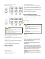
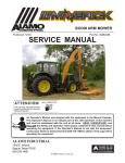
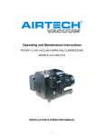
Connection Scheme Alternating Current Motor
Low voltage connection:
• Make sure that an overload protection according to EN 60204-1 is
provided for the drive motor
• Make sure that the drive of the side channel blower will not be affected
by electric or electromagnetic disturbance from the mains; if necessary
seek advice from the vacuvane service
In case of mobile installation:
• Provide the electrical connection with grommets that serve as strainrelief
Controlling Pressure/Flow
Vacuum operation:
• In order to relieve excess vacuum or to limit the air flow use vent valves.
Do not control the vacuum or the flow by throttling of suction or discharge
lines. Conveying bypass air will let the side channel blower run cooler and
draw less power.
Pressure operation:
• In order to relieve excess pressure or to limit the air flow use bleed
valves. Do not control the pressure or the flow by throttling of suction or
pressure lines. Bleeding excess air will let the side channel blower run
cooler and draw less power.
High voltage connection:
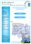
Connection Scheme Three-Phase Motor
Delta connection (low voltage):
• Make sure that the gas inlet (e) is open
• Make sure that all provided covers, guards, hoods etc. are mounted
• Make sure that cooling air inlets and outlets are not covered or ob-
structed and that the cooling air flow is not affected adversely in any
other way
In case the side channel blower comes with an eyebolt for the attachment of lifting gear:
• Make sure that the eyebolt is firmly tightened
Recording of Operational Parameters
Star connection (high voltage):
As soon as the side channel blower is operated under normal operating
conditions:
• Measure the drive motor current and record it as reference for future maintenance and troubleshooting work
Operation Notes
Use
CAUTION
The side channel blower is designed for operation under the conditions described below.
In case of disregard risk of damage or destruction of the side
channel blower and adjoining plant components!
CAUTION
Operating in the wrong direction of rotation can destroy the side
channel blower in short time.
Risk of injury!
The side channel blower must only be operated under the conditions described below.
Prior to starting-up it must be made sure that the side channel
blower is operated in the proper direction.
The side channel blower is intended for
NOTE: If certain applications require reverse operation over short periods,
please seek advice from your vacuvane representative!
Version with three-phase motor:
• Determine the intended direction of rotation with the arrow (stuck on or
cast)
• "Bump" the drive motor
• Watch the fan wheel of the drive motor and determine the direction of
rotation just before the fan wheel stops
If the rotation must be changed:
• Switch any two of the drive motor wires (three-phase motor)
Connecting Lines/Pipes
• Connect the suction line
• Connect the discharge line
or
• Connect the pressure line
Installation without discharge line:
• Make sure that the gas discharge (d) is open
Installation without suction line:
- the suction
- the compression
of
- air and other dry, non-aggressive, non-toxic and non-explosive gases
Conveying media with a higher density than air leads to an increased
thermal and mechanical load on the side channel blower and is permissible
only after prior consultation with vacuvane.
The gas shall be free from vapours that would condensate under the
temperature and pressure conditions inside the side channel blower.
The side channel blower is intended for the placement in a non-potentially
explosive environment.
The side channel blower is suitable for continuous operation, provided that
the housing can transmit heat to the environment unobstructedly and a
certain minimum gas transfer is warranted. If there is a risk that the side
channel blower may be operated against a closed inlet or outlet for more
than a few seconds, a vacuum or pressure relief valve, respectively, shall
be provided. Frequent switching on and off leads to increased coil
temperatures. In case of doubt seek advice from your vacuvane
representative!
The nominal value (=reference value for performance data) for the
temperature of the process gas is 15°C. The max. allowed temperature of
the inlet gas is 40 "C.
The nominal value for the ambient temperature is 25°C. The min. allowed
ambient temperature is -30°C. The max. allowed ambient temperature is
40°C.
Binding data with regard to the allowed differential pressure are to be read
from the nameplate (value with negative sign ("-") for vacuum operation,
value without sign for pressure operation). The data is valid for ambient
temperatures up to 25°C and location altitudes up to 1000 m above sea
level. Higher ambient temperatures reduce the allowed differential
pressures by up to 10 percent at 40°C. In case of placement in altitudes
beyond 1000 m above sea level the allowed differential pressure shall be
agreed upon with vacuvane.
The maximum allowed pressure on the pressure connection (d) is
2 bar abs. By means of process control and/or pressure relief
valves it must be made sure that the maximum allowed pressure
will not be exceeded.
Maintenance
DANGER
In case the side channel blower conveyed gas that was
contaminated with foreign materials which are dangerous to
health, harmful material can reside in filters.
Danger to health during inspection, cleaning or replacement
of filters.
Danger to the environment.
CAUTION
During operation the surface of the side channel blower may reach
temperatures of more than 70°C.
Personal protective equipment must be worn during the
handling of contaminated filters.
Contaminated filters are special waste and must be disposed
of separately in compliance with applicable regulations.
Risk of burns!
The side channel blower shall be protected against contact during
operation, it shall cool down prior to a required contact or heat protection gloves shall be worn.
CAUTION
During operation the surface of the side channel blower may
reach temperatures of more than 70°C.
CAUTION
Depending on the construction size the side channel blower may emit
noise of high intensity.
Depending on the operating state the side channel blower may emit
noise in a narrow band.
Risk of damage to the hearing.
Persons staying in the vicinity of a non noise insulated side channel
blower over extended periods shall wear ear protection.
• Make sure that all provided covers, guards, hoods etc. remain
mounted
• Make sure that protective devices will not be disabled
• Make sure that cooling air inlets and outlets will not be covered or
obstructed and that the cooling air flow will not be affected adversely
in any other way
• Make sure that the "Installation Prerequisites" are complied with and
will remain complied with, particularly that a sufficient cooling will be
ensured
Risk of burns!
• Prior to disconnecting connections make sure that the connected
pipes/lines are vented to atmospheric pressure
Maintenance Schedule
NOTE: The maintenance intervals depend very much on the individual
operating conditions. The intervals given below shall be considered as
starting values which should be shortened or extended as appropriate.
Particularly heavy duty operation, such like high dust loads in the environment or in the process gas, other contaminations or ingress of process
material, can make it necessary to shorten the maintenance intervals
significantly.
Monthly:
• Make sure that the side channel blower is shut down and locked against
inadvertent start up
In case an inlet air filter is installed:
• Check the inlet air filter, if necessary clean (with compressed air) or
replace
In case of operation in a dusty environment:
• Clean as described under" Every 6 Months:"
Every 6 Months:
• Make sure that the housing is free from dust and dirt, clean if necessary
• Make sure that the side channel blower is shut down and locked against
inadvertent start up
• Clean the fan cowling, the fan wheel, the ventilation grille and the
cooling fins
Every Year:
• Make sure that the side channel blower is shut down and locked against
inadvertent start up
In case an inlet air filter is installed:
• Clean (with compressed air) or replace the inlet air filter In case an inlet
screen is installed:
• Check the inlet screen, clean if necessary
Overhaul
Dismantling and Disposal
CAUTION
DANGER
In order to achieve best efficiency and a long life the side channel
blower was assembled and adjusted with precisely defined tolerances.
This adjustment will be lost during dismantling of the side channel
blower.
It is therefore strictly recommended that any dismantling of the
side channel blower that is beyond of what is described in this
manual shall be done by vacuvane service.
In case the side channel blower conveyed gas that was
contaminated with foreign materials which are dangerous to
health, harmful material can reside in pores, gaps and
internal spaces of the side channel blower.
Danger to health during dismantling of the side channel
blower.
Danger to the environment.
During dismantling of the side channel blower personal
protective equipment must be worn.
DANGER
In case the side channel blower conveyed gas that was
contaminated with foreign materials which are dangerous to
health, harmful material can reside in pores, gaps and
internal spaces of the side channel blower.
Danger to health during dismantling of the side channel
blower.
The side channel blower must be decontaminated prior to
disposal.
• Make sure that materials and components to be treated as special waste
have been separated from the side channel blower
• Make sure that the side channel blower is not contaminated with
harmful foreign material
Danger to the environment.
Prior to shipping the side channel blower shall be
decontaminated as good as possible and the contamination
status shall be stated in a "Declaration of Contamination"
(form downloadable from www.vacuvane.com).
vacuvane service will only accept side channel blowers that come with a
completely filled in and legally binding signed "Declaration of Contamination" (form downloadable from www.vacuvane.com).
Removal from Service
Temporary Removal from Service
• Prior to disconnecting pipes/lines make sure that all pipes/lines are
vented to atmospheric pressure
Recommissioning
• Observe the chapter" Installation and Commissioning"
According to the best knowledge at the time of printing of this manual the
materials used for the manufacture of the side channel blower involve no
risk.
• Dispose of the side channel blower as scrap metal
Spare Parts
Only the bearings are intended as spare parts. Commercially available
standard parts are to be purchased on the open market. If an overhaul
requires parts other than bearings or standard parts your vacuvane
representative will clarify whether an overhaul is economic or a
replacement side channel blower should be considered.
NOTE: When ordering spare parts or accessories always quote the type
and the serial no. of the side channel blower (data on the nameplate).