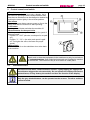
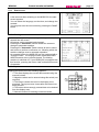
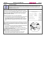
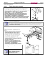
1
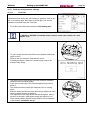
Operating Instructions
MOBI 500
(semi-automatic RingWire Binding Machine )
Renz International
Firmensitz
Headquarter
Siège
Domicilio social
Renz America Co. Inc.
Renz France SARL
92, Almgren Drive
Agawam MA 01001
59 CD 201
68390 Sausheim
U.S.A.
France
Phone: +1 (413) 789-7700
Fax: +1 (413) 789-7706
Phone: +33 (0) 3/89618324
Fax: +33 (0) 3/89617445
e-mail: [email protected]
e-mail: [email protected]
Renz Canada Corp.
Manuf. Celuloide Podesta S.A.
Rechbergstr. 44
73540 Heubach
Queensway E, Unit 28
Mississauga Ont. L4Y 4C5
Germany
Canada
Melo 349
1752 Lomas del Mirador
Buenos Aires
Argentina
Phone: + 49 (0) 7173/186-0
Fax: + 49 (0) 7173/3720
Phone: +1 (905) 896-4040
Fax: +1 (905) 896-8508
Phone:+54 (0) 11 4699 0800
Fax: +54 (0) 11 46 99 06 80
e-mail: [email protected]
e-mail: [email protected]
Chr. RENZ GmbH
e-mail: [email protected]
Internet: www.renz.com
Renz Italia SRL
Renz U.K. Ltd.
Renz do Brasil
Hill End Farm
Hill End
Hatfield Herts AL 9 5PQ
Rua Treze de Maio; 474-Vila Tarumã
83323-160 Pinhais PR
Great Britain
Brasil
Phone: +44 (0) 1707 27 00 01
Fax: +44 (0) 1707 27 17 69
Phone: +55 41 668-2392
Fax: +55 41 668-1779
e-mail: [email protected]
Internet: http://www.renz.co.uk
e-mail: [email protected]
Renz Masterbind
RENZTURK KIRTASIYE IMALAT
Via Delle Noci, 18/D
Treviolo (Bergamo) 24048
St Leonards Corporate Centre
Unit 14, 39 Herbert Street
St Leonards NSW 2065
SAN.TIC.LTD.STI.
ALINTERI BULVARI NO:29/A3
TR-06370 OSTIM / ANKARA
Italy
Australia
Turkey
Phone: +39 (0)35 692086
Phone: +61 (0) 294939493
Fax: +61 (0) 294939444
e-mail: [email protected]
Internet: www.renz.com
Phone: +90 312 386 13 12
Fax: +90 312 386 13 11
e-mail: [email protected]
Internet: www.renz.com
e-Mail: [email protected]
Internet: www.renz.com.tr
copyright© Chr. Renz GmbH
Table of contents
MOBI500
1
page 2
Table of contents
1
Table of contents ...................................................................................................2
2
EC Declaration of Conformity...............................................................................4
3
As-delivered condition of your MOBI 500............................................................5
4
Product description ...............................................................................................6
4.1
4.2
4.3
Intended use ................................................................................................................................................................... 6
Description of operation ................................................................................................................................................ 6
Description of operational sequence............................................................................................................................ 6
5
General safety advice ............................................................................................7
5.1
5.2
5.3
5.4
5.5
5.6
5.7
Operator’s duty of care .................................................................................................................................................. 7
Safety advice .................................................................................................................................................................. 7
Explanation of Symbols................................................................................................................................................. 8
Safety precautions during normal operation ............................................................................................................... 9
Safety precautions during maintenance ...................................................................................................................... 9
Work on electrical equipment ..................................................................................................................................... 10
Environmental standards ............................................................................................................................................ 10
6
Transport and start-up ........................................................................................11
6.1
6.2
6.3
6.4
6.5
6.6
6.7
Safety advice regarding transport .............................................................................................................................. 11
Unpacking the machine ............................................................................................................................................... 11
Lifting points when transporting with industrial trucks............................................................................................ 12
Space requirements and assembly............................................................................................................................. 12
Electrical connections ................................................................................................................................................. 13
Start-up.......................................................................................................................................................................... 13
Assembly of the pay off ............................................................................................................................................... 13
7
RENZ MOBI 500 - technical data.........................................................................14
7.1
7.2
7.3
7.4
7.5
Binding formats ............................................................................................................................................................ 14
Electrical connections ................................................................................................................................................. 14
Space requirement ....................................................................................................................................................... 14
Site conditions.............................................................................................................................................................. 14
Weights ......................................................................................................................................................................... 14
8
RENZ RING WIRE ® Table....................................................................................15
9
Control console and switch ................................................................................16
9.1
Individual screens ........................................................................................................................................................ 16
9.1.1
9.1.2
9.1.3
9.1.4
9.1.5
9.1.6
Start screen ....................................................................................................................................................17
Settings ..........................................................................................................................................................17
Input screen....................................................................................................................................................17
Parameters:....................................................................................................................................................18
Reference run:................................................................................................................................................18
Automatic mode: ............................................................................................................................................18
10
Setting up the MOBI 500......................................................................................19
10.1
10.2
10.3
10.4
10.5
10.6
10.7
10.8
10.9
Changing the RING WIRE spool.................................................................................................................................. 19
Changing the paper separation spool ........................................................................................................................ 20
Square up angle ........................................................................................................................................................... 20
Cover for small sizes.................................................................................................................................................... 21
Paper guiding rail ......................................................................................................................................................... 21
Changing the feed wheel (2:1 or 3:1 pitch) ................................................................................................................ 22
Changing the input guide ............................................................................................................................................ 23
Adjusting the guide slot on the hanger station ......................................................................................................... 24
Adjusting the closing unit ........................................................................................................................................... 24
10.9.1
10.9.2
10.9.3
10.9.4
10.9.5
Adjusting the stroke limiter: ............................................................................................................................24
Adjusting the rear guide rail ...........................................................................................................................25
Adjusting the front guide rail...........................................................................................................................25
Adjusting the clamping rail/lower position ......................................................................................................26
Adjusting the clamping rail/upper position .....................................................................................................26
10.10
Entering display data ................................................................................................................................................... 27
10.10.1
10.10.2
10.10.3
Settings.......................................................................................................................................................27
Clamp settings on the display.....................................................................................................................28
Programming the counter ...........................................................................................................................28
MOBI500
10.10.4
10.10.5
10.11
10.11.1
10.11.2
10.12
10.12.1
10.12.2
Table of contents
page 3
Preset counter ............................................................................................................................................28
Step by step mode......................................................................................................................................29
Feed test and parameter settings ............................................................................................................................... 31
Feed test.....................................................................................................................................................31
Parameter settings......................................................................................................................................32
Delivery device ............................................................................................................................................................. 33
Simple delivery device (standard) ..............................................................................................................33
Conveyor belt (optional) .............................................................................................................................33
11
Short overview "Setting up the MOBI500" ........................................................34
12
KA300(R) hanger dispenser................................................................................35
12.1
KA300 ............................................................................................................................................................................ 35
12.1.1
Installation KA300 ..........................................................................................................................................35
12.2
KA300R hanger dispenser from reel (optional) ......................................................................................................... 36
12.2.1
12.2.2
12.2.3
12.2.4
12.2.5
Installation KA300R........................................................................................................................................36
Change of the hanger reel .............................................................................................................................36
Alignment of the reel ......................................................................................................................................37
Fixing of the adhesive tapes ..........................................................................................................................37
Alignment of the scrapers ..............................................................................................................................38
13
Error messages ....................................................................................................38
13.1
Error messages on the display ................................................................................................................................... 38
13.1.1
13.1.2
13.1.3
13.1.4
Incorrect input.................................................................................................................................................38
Hanger empty.................................................................................................................................................38
Fault on the hanger device.............................................................................................................................39
Fault in the closing device..............................................................................................................................39
14
Troubleshooting...................................................................................................39
14.1
Faults when drawing in loops ..................................................................................................................................... 39
14.1.1
Faults when inserting the hanger ...................................................................................................................40
14.2
14.3
14.4
Faults in transporting of the material to be bound into the closing unit................................................................. 40
Poor binding ................................................................................................................................................................. 40
General faults ............................................................................................................................................................... 40
15
Default values and factory settings ...................................................................41
15.1
15.2
Default in the settings display..................................................................................................................................... 41
Values in the parameter display.................................................................................................................................. 41
16
some space for your notes .................................................................................42
MOBI500
2
EC Declaration of Conformity
page 4
EC Declaration of Conformity
According to EC Directives
EC Machinery Directive 98/37/EC
Electromagnetic compatibility according to 89/336/EEC as modified by 93/31/EEC
Low-voltage 73/23/EEC
The following equipment:
Product:
Type:
Valid from machine no.:
Year of construction:
Semi-automatic binding machine
MOBI 500
1024
April 2007
was developed, designed and manufactured according to the above EC Directives exclusively by
Company:
Chr. Renz GmbH, Rechbergstraße 44, D-73540 Heubach
The following harmonised standards were applied:
EN ISO 12100-1, Safety of Machinery, Basic concepts, general principles for design
EN 60204-1, Safety of Machinery, Electrical Equipment of Machines
....................................................................................................................................
....................................................................................................................................
....................................................................................................................................
....................................................................................................................................
The following national standards, guidelines and specifications were applied:
....................................................................................................................................
....................................................................................................................................
....................................................................................................................................
Complete technical documentation is available.
The machine’s manual is available
; in the original version
; in the following European languages:
Heubach, April 2007
(Place, date)
Signature
German, English
Managing Director
(Position)
MOBI500
3
As-delivered condition of your MOBI 500
page 5
As-delivered condition of your MOBI 500
Machine number:
Year of construction :
Pitch (en):
4050016
.
/
2:1
3:1
Voltage:
V
Frequency :
Hz
PLC- program :
Display- program :
Calendar hanger tool:
KA
s/n
.
no cal. hanger tool
standard delivery device
Delivery device:
conveyor belt
s/n
.
Additional accessories :
Heubach, 22 May. 07
signature
Product description
MOBI500
4
page 6
Product description
4.1
Intended use
The RENZ® MOBI 500 binding machine is exclusively intended for binding with a wire comb. As an
option, the wire comb elements can also be cut.
The machine is not intended for applications other than those specified here
Non-compliance with this manual will be considered to be inappropriate use!
In particular, we point out that the following is not allowed:
The uses of the machine for purposes other than binding with wire comb elements.
Danger
4.2
• If the MOBI 500 is not used in accordance with these requirements, the safe
operation of the machine cannot be guaranteed.
• Any damage to property and persons resulting from inappropriate use is the
responsibility of the operator of the machine, not the manufacturer.
Description of operation
The RENZ MOBI500 is a semi-automatic wire comb binding machine.
It binds wire combs from 50 –500mm in length and a diameter of 3/16" – – 11/4“.
A calendar hanger feed (KA300), available as an option, enables an automatic feed of calendar
hangers during the binding process.
It is possible to skip bind up to 3 elements as standard.
4.3
•
•
•
•
•
•
•
Description of operational sequence
The product to be bound is fitted into the available wire comb elements.
On pressing the foot pedal, the product is transported to the right into the binding unit.
At the same time a new wire comb is positioned ready (with the KA300 option, the calendar hanger
also drops into the elements).
The product is clamped in the binding unit and moved upwards.
The upper position is now bound.
When the binding procedure has ended, the closing bar moves back far enough to allow the
finished bound product to slide downward into the magazine.
The machine is now ready for a new binding cycle.
General safety advice
MOBI500
5
5.1
page 7
General safety advice
Operator’s duty of care
•
•
The MOBI 500 binding machine has been designed and built according to
carefully selected harmonised standards and additional technical
specifications. It therefore meets the latest technical standards, offering the
highest possible level of safety in operation.
However the machine can only be operated safely if all the required steps are
taken. It is a part of the operator’s duty of care to plan for and monitor the
execution of these steps.
In particular the operator must ensure that
•
•
•
•
•
•
•
•
5.2
The machine is only used as intended
The machine is only operated when in perfect functional condition and the
safety devices in particular are regularly checked for their functionality.
Existing safety devices must not to be altered or defeated.
The personal safety equipment required for personnel involved in operation,
maintenance and repair must be available and be worn.
The manual is legible and complete, and is always available where the machine
is used.
The machine may only be operated, serviced and repaired by qualified and
authorised personnel.
Such personnel are given regular training in all matters relating to health and
safety and the protection of the environment, and should be conversant with
the manual and in particular the safety advice contained in it.
All safety and warning notices attached to the machine should not be removed
and must be legible.
Safety advice
These operating instructions provide valuable safety advice regarding unavoidable residual risks that
exist in the operation of the machinery.
These residual risks may pose danger to:
• Personnel, in particular operators
• The product and the machine
• The environment
MOBI500
5.3
General safety advice
page 8
Explanation of Symbols
The symbols listed below appear in the operating instructions where appropriate, highlighting the
specified residual risks.
This symbol indicates a particular risk to personnel! (danger to life, risk of injury)
Danger
This symbol indicates a particular risk to the equipment, the material and / or the
environment. (damage, collision)
Caution
This symbol indicates an electrical risk. (See also Chapter 5.6) (danger to life, risk
of injury or fire)
This symbol indicates a risk of crushing hands and fingers.
Stickers have been placed on the machine at the relevant position.
The main aim of this health and safety advice is to prevent personal injuries.
• If a warning triangle marked “Danger” is placed next to safety advice, this does not exclude the
possibility of risks to the equipment, material and / or the environment as well.
• If the warning triangle indicating electrical danger is placed next to safety advice, this does not
exclude the possibility of risks to the machine, material, environment and personnel.
• If the warning triangle marked “Warning” is placed next to safety advice, there is no risk to
personnel.
In all cases, the symbol does not replace the text of the safety advice. The text must always be
read thoroughly!
This symbol indicates matters of special importance to the operator and/or provides
further information to assist in understanding the workings of the machine.
information
MOBI500
5.4
General safety advice
page 9
Safety precautions during normal operation
• The machine may only be operated by personnel who are authorised and
trained in its use, who are conversant with the manual and can work
according to the instructions laid down in it.
Before switching on the machine, check and make sure that
• only authorised personnel are present in the working area around the
machine and that nobody can be injured when the machine starts up.
• before starting production, check the machine for visible damage and make
sure that it is only operated if it is in perfect condition! Any defects should be
reported to the operator’s superior immediately.
• before starting production, remove all material and items not required for
production from the work area around the machine.
• before starting production, ensure all safety devices are functioning correctly!
5.5
Safety precautions during maintenance
Keep to the inspection and maintenance intervals laid out in the manual.
Pay attention to the repair and maintenance manuals for the individual components
in this instruction booklet.
Warning
Before carrying out maintenance or repair work, bar access to unauthorised
personnel in the work area around the machine! Attach or set up a sign drawing
attention to the fact that maintenance or repair work is being carried out.
Before maintenance and repair work is carried out, switch off at the mains and
secure the electricity supply with a padlock. The key to this lock must be in hands
of the person who is carrying out the maintenance or repair work. Furthermore the
machine must be disconnected from the mains.
When changing heavy machine parts, only use only suitable lifting devices and
slinging equipment.
Before maintenance and repair work is carried out ensure that all parts of the
machine with which contact may be made have cooled down to ambient
temperature.
Dispose of environmentally hazardous lubricating, cooling or cleaning agents in a
responsible manner.
MOBI500
5.6
General safety advice
page 10
Work on electrical equipment
Repair work on electrical equipment in the machine may only be carried out by a
trained electrician.
• Examine electrical equipment regularly.
• Tighten loose connections immediately.
• Change damaged conductors / cables immediately.
• Always keep the switchgear cabinet closed. Access is restricted to authorised
personnel with the appropriate key and tools.
• Never clean switchgear cabinets and other electrical equipment housings by
hosing down with water.
5.7
Environmental standards
When working on, or with the machine, adhere to all legal requirements avoiding
the production of waste, recycling and disposal. It is of particular importance during
installation, repair or maintenance work that the following pollutants do not enter the
groundwater, or drainage system:
• Lubricating greases and oils
• Hydraulic oils
• Cooling agents
• Cleaning fluids containing solvents
These materials must placed in suitable containers, transported away from the
machine, collected and disposed of.
MOBI500
6
Transport and start-up
page 11
Transport and start-up
6.1
Safety advice regarding transport
Danger
6.2
To prevent damage to the machine and possible lethal injuries during transport,
the following should be considered:
• Lifting devices and slinging equipment must meet the requirements of the
regulations for the prevention of industrial accidents.
• When choosing lifting devices and slinging equipment, take account of the
weight of the MOBI 500 (approximately 500kg).
• The routes over which the equipment is to be transported should be closed off
and marked out such that no unauthorised personnel can enter the danger area.
• The transport of the equipment may only be carried out by qualified authorised
personnel.
• The individual components of the machine may only be transported with a forklift truck or a pallet truck that has sufficient load carrying capacity
• Use only those lifting devices that have forks of a sufficient length to reach
through the entire machine frame, thus ensuring safe transport conditions.
• Take note of the position of lifting points in the diagram below
• Transport across ramps should only be attempted with suitable lifting devices
Unpacking the machine
If the machine has been delivered in a transport crate, please proceed as follows:
• Undo the screws on the upper cover. Remove the cover.
• Undo the screws on the sides and remove them.
• Remove the machine’s rear and side covers.
• Remove the clamps that fasten the machine to the floor of the crate.
• Remove the accessories, which can be found inside the machine.
• Using a suitable stacker truck, lift the MOBI 500 off the floor of the crate.
• The sides and the cover of the transport crate are relatively heavy. Two people
are needed to remove these items.
Danger
• When transporting the machine and lifting it from the floor of the crate, ensure
the cables are not damaged.
Caution
MOBI500
6.3
Transport and start-up
page 12
Lifting points when transporting with industrial trucks
• Place the forks of the stacker truck or pallet
truck as wide apart as possible.Lift the
machine in the centre, by its frame (see
diagram on left).
• On steep slopes, do not use with lifting devices
that have no brakes.
6.4
Space requirements and assembly
•
•
•
Caution
Please note that for safe
operation of the machine, the
operator’s work space must be
sufficiently large.
The machine should be set up on
an even and stable surface.
Please note the additional space
requirement when using the
swinging spool lift.
• The weight of the MOBI 500 (approximately 500kg without calendar tool) is
distributed over four castors. Take care to ensure that the floor is sufficiently
strong and stable.
Transport and start-up
MOBI500
6.5
Electrical connections
•
•
•
•
6.6
page 13
The voltage is 230V (single phase) 50Hz [where required, 115V (single phase) 60Hz]
The socket must be earthed.
The socket must be equipped with a 16 A fuse.
If you are uncertain as to whether, or not the socket meets the specification, please
consult an electrician before start-up.
Start-up
To prevent people from tripping:
• Lay the cable in such a way that there is no risk of tripping (use troughs, bridges etc.)
Danger
To ensure smooth running of the machine:
• Prepare the area such that the machine stands horizontally on an even floor.
• Lay the cable such that there is no tensile load placed on the plugs.
• Avoid chafing on the cable.
Before starting the MOBI 500 for the first time, check:
• Have all transit supports and desiccation bags been removed?
• Is the electrical connection correct?
Information • Are all safety devices bolted on?
Information
6.7
Before starting the MOBI 500 for the first time, the following tasks must be carried
out:
• Clean the painted surfaces and the metal parts in the working area with a mild
cleaning agent, in order to remove any traces of rust preventing fluid that has
been applied for transport.
Assembly of the pay off
Where the machine is delivered in a wooden
box, the pay-off arm is dismantled.
To assemble please proceed as follows.
•
•
•
•
Remove both screwsd from the four
cornered bare.
Push the payoff arm with the square
sectioned tubec over the bar from
above.
Secure the payoff arm with the two
screws.
Put the plug into the socket underneath
the cut-out in the sheet metal.
RENZ MOBI 500 - technical data
MOBI500
7
RENZ MOBI 500 - technical data
7.1
Binding formats
Bound side
min. 50 mm - max. 500 mm
Unbound side
min. 90 mm
Block thickness
max. 27 mm
®
RENZ RING WIRE
3/16" – 1 1/4 "
Pitches
Standard: 3:1 and 2:1
Mechanical output
1000 bindings per hour
7.2
Electrical connections
Voltage
See page 5
Average power demand
600 VA
Max. power demand
900 VA
Type of protection
IP42
7.3
Space requirement
Length
approximately 2.9 m
Width
approximately 1.5 m
Height
approximately 2.0 m
7.4
Site conditions
Ambient temperature (in operation)
min. 15°C - max. 35°C
Ambient temperature (when not in use)
min. 5°C - max. 50°C
Maximum air humidity:
Max. 85% relative air humidity (non-condensing)
7.5
page 14
Weights
MOBI 500 binder
500 kg (approximately net without calendar device)
MOBI 500 with packing (wooden box)
640 kg (approximately gross without calendar device)
RENZ RING WIRE ® Table
MOBI500
page 15
RENZ RING WIRE ® Table
8
Ø
pitch
max. book
thickness w/o
hanger
max. book
thickness with
hanger
min. binding
width
max.
binding
width
rcommended perforation
cross section in mm
rectangular
round hole
hole
inch
mm
loops /
inch
3/16“
5,5
3:1
3,0
2,5
50
500
4,0 x 4,0
Ø 4,5
1/4“
6,9
3:1
5,0
4,5
50
500
4,0 x 4,0
Ø 4,5
5/16“
8,0
3:1
6,0
5,5
50
500
4,0 x 4,0
Ø 4,5
3/8“
9,5
3:1
7,5
7,0
50
500
4,0 x 4,0
Ø 4,5
7/16“
11,0
3:1
9,0
8,5
50
500
4,0 x 4,0
Ø 4,5
1/2“
12,7
3:1
10,0
50
500
4,0 x 4,0
Ø 4,5
9/16“
14,3
3:1
11,0
50
500
4,0 x 4,0
Ø 4,5
5/8“
16,0
2:1
13,5
100
500 c
6,0 x 6,0
Ø 6,0
3/4“
19,0
2:1
15,0
100
500 c
6,0 x 6,0
Ø 6,0
7/8“
22,0
2:1
18,0
100
500 c
6,0 x 6,0
Ø 6,0
1“
25,4
2:1
20,0
100
500 c
6,0 x 6,0
Ø 6,0
1 1/8“
28,5
2:1
23,0
100
500 c
6,0 x 6,0
Ø 6,0
1 1/4“
31,7
2:1
26,0
100
500 c
6,0 x 6,0
Ø 6,0
c In the case of products from 5/8"to 1 1/4 " with product lengths of 300mm to 500mm and full block thickness, problems can occur when
binding due to the weight and condition of the paper. As a result of the higher weight and possibly too little clamping friction between the
pages it is possible that the product is not shifted upward into the binding position correctly. Before processing large numbers, such products
should first be tested on the MOBI 500.
•
•
Information •
Calendars with hangers should only be bound with diameters from 1/4"to 3/8".
With diameters of 7/16" and above the hanger slides out of the binding.
Please refer to the table above when selecting the perforation, the binding
diameter and the block thickness.
Increasing the block thickness beyond the values specified above will inevitably
lead to problems in quality and production.
MOBI500
9
Control console and switch
page 16
Control console and switch
cTouch screen surface
The touch screen display is not only a display, but is
also used for inputting machine and production data.
Data that can be altered can be changed or deleted by
touching the screen lightly in the relevant position.
dOn button
Pressing the green button causes power to flow to the
control units and the machine to start operating
e Off button
Pressing the red button switches the machine off.
fPotentiometer for the spool drive
With this potentiometer you can regulate the speed of
the spool payoff.
• Position "0" = OFF (the wire comb spool is not paid
off )
• Position "1" - "10" = (the wire comb spool is paid
off. The higher the value, the faster the payoff
speed)
hMain switch
The main switch is on the switchbox door at the back
of the machine.
Repair work on electrical equipment in the machine may only be carried out
by a trained electrician. Only authorised personnel are permitted to opening
the control box. The control box key is to be stored in a safe place.
Danger
9.1
Individual screens
The touch screen has a contact-sensitive surface. Lightly tapping the appropriate
virtual button triggers the relevant activity. Do not operate the display with hard or
pointed items, as they destroy the surface and thus the function of the display.
Caution
Only the grey shaded buttons can be operated on the screens. The other switches
cannot be used.
Information
MOBI500
9.1.1
Control console and switch
Start screen
• A few seconds after switching on the MOBI 500, the start
screen appears.
• You can select the language, set the time, and change the
contrast.
• You progress onto the next screen by pressing the "next"
button
9.1.2
Settings
• All the data required to process a particular product can be
entered into the screen.
• All buttons can be operated and changed.
• Pressing the "Parameter" switch causes the screen to
change to parameter settings.
• Pressing the "Automatic" switch causes all servo motors
and knives to perform a reference run, following which the
machine changes over to automatic operation.
• As a special option, the MOBI 500 can be equipped with a
"cutting function". The cutting function means that RING
WIRE elements are cut off and ejected. The binding
machine is switched off. If your MOBI 500 is equipped with
this function, pressing the button "cut" activates this mode
of operation.
9.1.3 Input screen
When operating buttons that require numeric inputs, after
tapping the input screen the following appears:
•
c This area displays the current data entered using the
numeric buttons.
•
d Negative values can be entered using this switch (not
required).
•
e This button causes the value in the display to be
accepted. The input screen closes after this button has
been pressed.
•
f This button allows wrongly entered data to be deleted
from the display area.
•
g Numeric buttons for entering numerical values.
page 17
MOBI500
9.1.4
Control console and switch
Parameters:
• In the parameter set up screen, the correction factors for the
servo motors can be set.
9.1.5
Reference run:
• This is a pure information screen. It appears until all the
servomotors and the knife have reached their start positions.
Once the starting positions have been reached, the screen
changes to Automatic or Cut mode (optional).
9.1.6 Automatic mode:
The automatic mode screen displays the currently entered data.
The following values can be changed during automatic operation:,
for example the input speed and switching the calendar feed on
or off. The output counter can be changed and a feed test can be
carried out.
• feeding speed
• hanger on/off
• piece counter
• clamp up/down
• conveyor
• step by step mode
• wire feeding test
page 18
MOBI500
Setting up the MOBI 500
page 19
10 Setting up the MOBI 500
10.1
Changing the RING WIRE spool
To change the RING WIRE spool please proceed as
follows.
•
•
•
•
Hold the feed plated with one hand.
Open the two release handlesc and lower the
feed plate into a horizontal position.
Tighten the two release handles again.
Move the pay-off arm down by turning the cranke
of the winch counter-clockwise
The spring is under pressure. If you open the release handle the spring and
the clamping device possibly jumps off the shaft. It could hurt you or your
colleagues. Please take care when you release the release handle.
Danger
•
•
•
•
•
•
•
Loosen the release handlecand remove the
clamping deviced and the compression springe
from the shaftf.
Take the spoolg off the shaft.
Push the new spool onto the shaft, so that the
RING WIRE pays off from the left side.
Push the compression spring and the clamping
device back onto the shaft.
Stretch the compression spring and tighten the
release handle.
Move the pay-off arm back to a vertical position.
Place the feed plate into a slanting position
again, so that the paid off wire rests comfortably
on the switching surface of the initiator
Setting up the MOBI 500
MOBI500
10.2
page 20
Changing the paper separation spool
Danger
The spring is under pressure. If you open the clamping lever the spring and the
clamping device possibly jumps off the shaft. It could hurt you or your colleagues.
Please take care when you release the clamping lever.
• Push an empty spool onto the take up shaft like described in
chapter 10.1.
• Stick the strip of separation paperc firmly onto the empty spool
• Lead the strip of separation paper down around the shaft of the
take up control.
• Take care to ensure that the strip of separation paper follows the
correct path (see sketch at the left).
10.3
Square up angle
To get the different layers of thicker books easier into the wire the square up angle is for.
Information
• This sheet metal anglec will be fixed at the front cover with
two magnet stripes. You can move this angle to any point at
the front cover.
• Place the sheet metal angle at a place where it does not
constrict your work.
• You can now square up your product to get it easier into the
wire.
Setting up the MOBI 500
MOBI500
10.4
page 21
Cover for small sizes
To avoid problems during the paper transport into the binding unit with small sizes
(smaller than 150mm) you must install a sheet metal cover.
Information
To install the cover please proceed as following:
• Switch off the Mobi 500 (main switch into pos. "0").
• Open the protection covere of the binding unit.
• Remove the lower rear clamping railc by releasing the
four allen screwsd.
• Put in the sheet metal coverf. It´ s been held by the
magnet stripes at its rear side.
• You can now operate sizes smaller than 150mm
because this area is now covered and the paper could
not hit any edges.
• If you want to go back to bigger sizes please switch
the main switch into pos. "0" and assemble the lower
rear clamping rail in reverse action to the above
mentioned sequence.
10.5
Paper guiding rail
To move the paper "trouble-free" into the binding unit, you must install the paper guiding
rail.
Information
The paper guiding railc lifts the paper in its lower area.
This makes sure that the paper will be transported without
any resistance. The paper will be high enough to get into
the delivery device.
• The paper guiding rail will be held by magnet stripes.
This enables you to fix it at any place at the front cover.
• Move the paper guiding rail to the lower third of your
product.
• If you change your size you possibly must change the
position of the paper guiding rail.
MOBI500
10.6
Setting up the MOBI 500
page 22
Changing the feed wheel (2:1 or 3:1 pitch)
To change the feed wheel please proceed as
follows:
•
Loosen the two screwsc on the dust coverd
and remove it.
• Loosen the three screwsc on the feed wheeld.
• Pull the feed wheel forward, removing it from the
shaft.
• Push the desired feed wheel onto the shaft and
tighten the screws up again.
• The 3:1 feed wheel has 36 teeth.
• The 2:1 feed wheel has 24 teeth.
Information
MOBI500
10.7
Setting up the MOBI 500
page 23
Changing the input guide
Danger
During the change of the input guides there is a high risk of crushing hands or fingers.
Please do not put you hands or fingers in the open area of the knife or the input
guides.
The MOBI 500 can process RING WIRE combs from 3/16"to 1 ¼". However each diameter
needs a special input guide.
Information
To change the input guide please proceed as follows.
• Pull the hand leverc forward. This moves entire knife
upward, freeing up the input guided.
• Remove the input guide from the machine.
The input guides are marked on their upper side by the relevant
RING WIRE diameter.
They have a continuous groove on the lower surface. (with
exception of the 3/16". This input guide has an ending groove).
• Push the appropriate input guide into the machine in such a
way that the groove engages with the two lower hexagonal
screwse.
• Push the hand leverc backwards carefully, so that the knife
is lowered again.
• There is also a hexagonal screwf on the lower surface of
the knife.
The complete input guide assembly can be adjusted
backwards and forwards.
Information
• Move the complete assembly backwards and forwards so
that the hexagonal screwf on the knife engages in the
grooveg on the top side of the input guide.
MOBI500
10.8
Setting up the MOBI 500
page 24
Adjusting the guide slot on the hanger station
The cut RING WIRE elements are transported into
the hanger station by a timing belt. The element is
led into a gap between two railsd. Depending on
the diameter, different thicknesses of wire are
used. The gap between the rails must also be
adjusted. Adjust the width of the gap using the two
adjusting knobsc.
• Turning the knob in a clockwise direction results
in the gap becoming narrower.
• Turning the knob in a counter clockwise
direction results in the gap becoming wider.
Caution
10.9
Please do not adjust the gap too
tightly, as this will cause the
RING WIRE element to catch. Make
sure the width of the gap is even.
Adjusting the closing unit
When changing the diameter, four adjustments must be made to the closing unit..
• The stroke limiter
• The rear guide rail
• The front guide rail
Information
• The clamping rail
Please maintain the order indicated
Caution
10.9.1 Adjusting the stroke limiter:
Turn the hand wheel on the stroke limiterc until
the indicator pine is against the desired size on
the scaled.
The fine tuning of the stroke limiter must be carried out in step by step mode during the
adjustment of the product.
Information
MOBI500
Setting up the MOBI 500
page 25
10.9.2 Adjusting the rear guide rail
Adjusting the hand wheeld, until the indicatorc
shows the desired diameter.
10.9.3 Adjusting the front guide rail
•
•
•
Open the star knob screw on the left side
opposed to the star know screwe at the right
side of the closing unit.
Hold the selected blocki between the two guide
railsj+k, and move the front guide railk as long
towards your product (by turning the star knob
screwe) as there is a gap of around 1mm
between the front guide rail and the block.
Tighten the star knob screw again on the left
side.
Always adjust the guide rail to the
processed product. A different book
thickness needs a different guide rail
Information adjustment.
Do not adjust the guide rails so that they are too close, otherwise the block can no
longer be moved.
Caution
MOBI500
Setting up the MOBI 500
page 26
10.9.4 Adjusting the clamping rail/lower position
• Depending on the height of the paper, the
clamping railg can be used in the lower or the
upper position.
• With paper heights > A5 (approximately 150mm)
the rail must be used in the lower position.
• To move the clamping rail please open the two
star knob screwsf and push the rail to either the
highest or the lowest final position.
When the screen is in “automatic operation” take care to ensue that the clamp is
either up or down.
Caution
10.9.5 Adjusting the clamping rail/upper position
• With paper heights < A5 the rail must be used in
the upper position.
• To move the clamping railg please open the two
star knob screwsf and push the rail to either the
highest or the lowest final position.
When the screen is in “automatic operation” take care to ensue that the clamp is
either up or down.
Caution
Setting up the MOBI 500
MOBI500
page 27
10.10 Entering display data
The touch-screen has a contact-sensitive surface. Lightly tapping the appropriate virtual
switches triggers the relevant activity.
Information
• Only use your fingers
• Do not operate the display with hard or pointed items, as they destroy the surface
and thus the function of the display.
Caution
In this example, data will be entered for a DIN A4 block, with 34 loops and a block thickness
of 8mm. In addition a wire comb with a diameter of 7/16"is used with a pitch of 3:1.
Information
Warning!
There is a danger of crushing hands and fingers in the binding mechanism.
Never reach into the binding mechanism!
Danger
• Switch on the MOBI 500.
• The start screen appears. Press the “next” switch.
10.10.1
Settings
• The settings screen appears.
• First press the first switch on the left at the top. This opens the
box for numeric input.
• Enter the value “34” and confirm with the “Enter” key.
Make sure you enter “0” in unused fields. The first
field should not contain a value of "0".
Information
• The pitch must be 3:1. If this is not the case, press the pitch
button for the division and enter the value “3”. Confirm with the
“Enter” key.
• The input speed can be changed later, in the automatic screen. you can enter any value from 5-100%.
• Now enter the paper width. In this case “2970” for A4.
• Select a suitable RING WIRE size by pressing the "+" or "-" keys. The final value for the relevant
size is stored in the control system and is called up automatically.
• If necessary, switch on the calendar hanger unit.
• After all inputs are complete please press the key “automatic”.
Warning! The machine now starts a reference run, i.e. all drives are switched on!
Danger
MOBI500
Setting up the MOBI 500
The machine carries out a reference run, i.e. all axles are set to
their start positions, after which the current configuration is set.
If all drives are successfully referenced, the machine changes
to the automatic screen.
10.10.2
Clamp settings on the display
After a successful reference run the automatic screen is
displayed.
Examine the position of the “clamp” switch.
Those actual position of the clamping rail, up or down,
must also be set in the display. If necessary, correct the
setting on the display.
10.10.3
Programming the counter
You can program the counter in this screen too.
Two different modes of operation are available.
Continuous counter:
Switch simply to “endless” by touching the right half of the
display area.
10.10.4
Preset counter
The preset counter counts from a pre-selected number back to
zero and then displays that the number of items has been
reached.
To program, please proceed as follows.
• Switch to “endless”.
• Now enter the desired number of items.
• Switch to “pre-selection”.
After the number of items has been reached, the
accompanying screen appears.
By pressing the “exit” switch you come straight back to
automatic mode, and the last pre-selected number of items is
displayed again.
page 28
MOBI500
10.10.5
Setting up the MOBI 500
Step by step mode
In order to check the settings, it is advisable to produce the first
item in step by step mode. Here the process is interrupted at
certain points, allowing you to check your settings.
•
•
•
•
•
Push the “automatic mode” button.
The display now shows “step by step mode”
Hang the block in the prepared RING WIRE element and
operate the foot switch. The block is transported into the binding
machine. The machine then stops.
When the foot switch is operated again, the block is clamped
and moved upward into the binding station. The machine stops
again.
You can now check if the settings of the stroke limiter are
correct.
Information
You must check which setting was selected for
the clamp. The description in this field applies to
the "clamp above" setting.
•
Where the “clamp above” setting is used, the block should be
moved sufficiently upwards so that the RING WIRE element
lightly presses against the upper plate of the binding station.
•
If the stroke limiter is positioned too far upward, the RING WIRE
element presses too heavily on the plate. Evidence of this is the
paper bulging out under pressure. This means the RING WIRE
element cannot move freely during the binding process and the
binding becomes out of round.
•
If the stroke limiter is positioned too far downward, the RING
WIRE element only presses against the plate on one side. This
misadjusted setting also results in a binding that is out of round.
page 29
MOBI500
Achtung
Setting up the MOBI 500
page 30
When set to “clamp down”, the paper is deliberately bent by a special device.
Because the block is effectively “shortened”, the stroke limiter must be set at around
1mm above the default value on the scale.
The sketch on the right shows the principle of the special device
that "bents" the paper.
There is a risk of crushing hands or feet in the area of the closing unit.
Never reach into the closing unit
Danger
•
Press the foot switch again.
The binding procedure is carried through and the machine
returns to the automatic operation.
If the binding is correct, you can begin production.
Otherwise switch the setting to step by step mode again and
carry out corrections to the settings as necessary.
Setting up the MOBI 500
MOBI500
page 31
10.11 Feed test and parameter settings
10.11.1
Feed test
If problems occur during the wire feeding-in process, such as too
few, or too many rings, bent loops or a loop jam, you should
check the loop feed using the “feed test”.
•
To do this, press the button marked “wire feeding test”.
If a KA300 or KA300R is installed please remove it now (see chapter 12.1 and
chapter 12.2)
Information
•
•
•
•
•
•
•
•
•
•
To get a visual access to the feed in area please remove the
upper coverd.
Remove the four screwsc and then the cover.
Pressing the button “feed wire” causes some loops to be
drawn in very slowly.
The picture on the right shows the loop transport assembly
(without knives and feed guide).
From the left, the loopse are first transported by the feed
wheelc.
The feed wheel then hands the elements over to a timing
beltd.
Both the wheel and the belt must be correctly aligned to each
other and take account of the pitch.
The alignment of the feed wheel and the timing belt, taking
account of the pitch, takes place during the reference run.
Their actual position relative to one another can be adjusted
in the screen “parameter set up”.
MOBI500
10.11.2
Information
Setting up the MOBI 500
page 32
Parameter settings
Both the feed wheel and the timing belt are referenced to a zero point by sensors. Their
subsequent movement away from the zero point depends on the values entered in the
“parameter set up” screen.
A value of 2.5 with “feed wheel 3:1” means that the feed wheel
continues to turn another 2.5mm after reaching the zero point.
In the case of all four parameters in both 2:1 and 3:1, an increase
in the value means that the RING WIRE element is positioned
further to the right. Similarly a reduction in the value means a
positioning further to the left.
A practical example of how to use the parameters.
• In the feed test you notice that the timing belt is positioned too
far to the left, the teeth do not mesh into the holes in the
RING WIRE elements, but instead bend the wire. You must
now increase the “timing belt” value for the ratio currently in
use.
Once the feed wheel and timing belt are positioned in accordance
with the pitch, you still need to control the cut. Examine a cut off
element. The wire sections on the left and on the right should be
of equal length.
• You can shift the cut to the left by increasing both parameters
(feed wheel – timing belt) by the same amount.
• Similarly you can shift the cut to the right by making them
smaller by the same amount.
The position of the pusherc can be adjusted using the parameter
“paper position”. This is the paper position in relation to the
position of the provided Ring Wire elements.
• With a higher value the pusher stops more to the right.
• With a lower value the pusher stops more to the left.
Setting up the MOBI 500
MOBI500
page 33
10.12 Delivery device
10.12.1
Simple delivery device (standard)
You can adjust the simple delivery device in the height and the
inclination. To adjust the height please proceed as following:
• hold the upper part of the delivery device with one hand and open
the release handlec with the other. You can now move the
delivery device up or down to the desired height.
• Close the release handle if you reached the desired height.
• Now move the delivery device as close as possible and in a
centred position to the binding unit of the Mobi 500.
• To adjust the delivery device to your size, please move the sheet
metal angled to a desired position. It is held by magnet stripes
and could be placed to any desired point of the delivery device.
10.12.2
Information
Conveyor belt (optional)
The optinal conveyor belt was designed for a higher output. The product will slide down
to the conveyor belt. The belt transports the product. At the end of the conveyor the
products will be scaled orderly.
To adjust the conveyor please proceed as
follows:
• Move the conveyor with the guiding sheet
metald as close as possible to the front
cover of the Mobi 500. The conveyor
should be centred to the binding device.
• Hold the upper part of the conveyor with
one hand and release the two release
handlese with the other. Move the
conveyor up- or downwards as long as the
guiding sheet metald is directly underneath
the paper guiding railc.
• Now adjust the two rollers. Move the two
anglesg forwards or backwards as long as
your productf will be picked and
transported by the belts. Possibly you must
correct the position of the rollers and the
duration after a while to get a better result
of scaling.
Information
You can change the duration of
the belt movement during the
automatic mode as well.
MOBI500
Short overview "Setting up the MOBI500"
page 34
11 Short overview "Setting up the MOBI500"
1.
2.
3.
4.
5.
6.
7.
8.
9.
10.
11.
12.
13.
14.
15.
16.
17.
18.
19.
20.
21.
22.
Choose an applicable Ring Wire diameter according to your product. Use the table from
chapter 8).
Change the Ring Wire spool to the desired diameter (see chapter 10.1) and fix the paper
separation stripe at the lower unwinding spool (chapter 10.2).
Check and if necessary change the feed wheel (chapter. 10.6).
Check and if necessary change the input guide (chapter 10.7)
Check and if necessary correct the guide slot (chapter 10.8).
If you work with sizes smaller than 150mm fix the additional cover if necessary (see
chapter 10.4). If you work with sizes bigger than 150mm please remove the additional
cover (see chapter 10.4) if necessary.
Adjust the stroke limiter to the desired Ring Wire diameter (see chapter 10.9.1).
Adjust the rear guide rail to the desired Ring Wire diameter (see chapter 10.9.2).
Adjust the front guiding rail (see chapter 10.9.3).
Set the clamping to the correct position in accordance to your size (chapter 10.9.4 and
chapter 10.9.5).
Switch on the Mobi 500. Enter the necessary production data at the display (number of
loops; pitch; feeding speed; paper width; Ring Wire diameter;). Please keep the value for
the calender hanger temporarily at the "off" position (see chapter 10.10).
Press the "Automatic" button (see chapter 10.10.1)
Change to "step by step" mode (see chapter 10.10.5)
Feed your product into the wire.
Change the clamping to the value "upper clamping" if necessary (see chapter 10.9.5)
Push the foot switch as often as the wire is in the upper position in the closing area. Readjust the stroke limiter if necessary ( see chapter 10.10.5).
Push the foot switch again. The product now is bound. Check your binding result and
correct if necessary.
Set the delivery device or the conveyor belt (see chapter 10.12.1 and chapter 10.12.2)
Change the clamping (lower/upper position) if necessary (see chapter 10.9.4 and
chapter 10.9.5)
Install and/or switch on the KA300(R) of you want to use it (see chapter 12).
Feed in your product and bind it in automatic mode. Check the binding result and correct
it if necessary.
You can start with your production if the binding result is ok.
KA300(R) hanger dispenser
MOBI500
page 35
12 KA300(R) hanger dispenser
12.1
KA300
12.1.1 Installation KA300
If you ordered the KA300 together with your MOBI500 it will be fixed and adjusted by the
factory. If you ordered it later you have to install and adjust it by yourself.
Information
To assemble the KA 300 hanger dispenser proceed as
follows:
• Place it on the holding device.
• Plug the cable into the socket to establish an electrical
connection.
• The disassembling happens in reverse action.
•
•
•
After opening the clamping screwsd, you can shift the
KA 300 sideways to locate it precisely on the RING
WIRE elements and/or the calendar.
You can adjust the height with the set screwsc. Please
set the height in such a way that the KA 300 does not
rest upon the plate below it, but there remains a gap of
around 1mm.
When the release handlese are opened, you can shift
the KA 300 back and forth. Please adjust the KA 300 in
such a way that it is positioned approximately 1mm in
front of the loop guide.
MOBI500
12.2
KA300(R) hanger dispenser
page 36
KA300R hanger dispenser from reel (optional)
12.2.1 Installation KA300R
If you ordered the KA300R together with your MOBI500 it will be fixed and adjusted by the
factory. If you ordered it later you have to install and adjust it by yourself.
Information
To assemble the KA 300 hanger dispenser proceed as
follows:
• Place it on the holding device.
• Plug the cable into the socket to establish an electrical
connection.
• The disassembling happens in reverse action.
•
•
•
After opening the clamping screwsd, you can shift the
KA 300 sideways to locate it precisely on the RING
WIRE elements and/or the calendar.
You can adjust the height with the set screwsc.
Please set the height in such a way that the KA 300
does not rest upon the plate below it, but there remains
a gap of around 1mm.
When the release handlese are opened, you can shift
the KA 300 back and forth. Please adjust the KA 300 in
such a way that it is positioned approximately 1mm in
front of the loop guide.
12.2.2 Change of the hanger reel
•
•
•
•
•
Open the star grip screwc.
Move the de-spooling shaft upwards off the holding
anglesh.
Release the knurled screwe at the right side an move
the set collar off the shaft. You can now pull off the empty
reel from the shaftd.
Move a full reel onto the shaft and fix it with the set collar.
Please remind that the hangers are wind off to the front.
Put the shaft back into the holding angles and tighten the
star grip screwc.
MOBI500
KA300(R) hanger dispenser
12.2.3 Alignment of the reel
•
•
•
Release the two knurled screws.e
Move the reelg on the shaft as long as it is in a centred
position in relation to the guiding railf. The formed part
of the hanger must be in a line with the guiding railf.
Tighten the knurled screws.
12.2.4 Fixing of the adhesive tapes
•
•
•
•
Put the adhesive tapesc through the scrapersd to the
rear.
At the rear side there is a re-winder shaft where you put
the adhesive tape onto. Glue the adhesive tape onto the
shaft. The correct track of the adhesive tape is shown at
the sketch at the lower right side.
If the shaft at the rear is "full" move the shaft forcefully to
the left. There is no clamping screw or anything else, just
move it to the left.
If you put back the shaft on place please take care for the
correct position. The slot at the right side (rear view) of
the shaft must fit to the pin in the hole.
page 37
MOBI500
Error messages
12.2.5 Alignment of the scrapers
The scrapers are adjustable to suit to the different reels. To
adjust them please proceed as follows:
• Open the knurled screwsc at the rear side of the
KA300R. Move the scrapers sidewards as long as they
suit to the adhesive tapes coming from the reel.
13 Error messages
13.1
Error messages on the display
13.1.1 Incorrect input
• When entering the number of loops, the value "0" may not be
entered into the first field (far left). If the value "0" is entered, an
error message appears.
• Press the "back" button and correct the entry.
13.1.2 Hanger empty
• When using the KA300 calendar feed device, the amount of
product on the curved hangers is permanently monitored.
• If the stocks appear to be running low, an error message is
displayed.
• Refill the hangers and then press the "exit" button.
page 38
MOBI500
Troubleshooting
page 39
13.1.3 Fault on the hanger device
•
•
•
•
When in use, the correct functioning of the KA300 calendar
supply device is constantly monitored.
When a fault occurs, the accompanying screen is displayed.
Please check that the KA300 is correctly positioned.
Disconnect the machine from the mains, and check the circuit
breakers in the switchgear cabinet.
13.1.4 Fault in the closing device
•
•
•
Where there is a fault in the closing device’s drive motor, the
accompanying screen is displayed.
Disconnect the machine from the mains, and check the circuit
breakers in the switchgear cabinet.
It also could only be an open protection cover. Please close the
cover.
14 Troubleshooting
14.1
•
Faults when drawing in loops
RING WIRE elements are paid off in an
uncontrolled manner, or pass by the inlet plate.
•
•
•
•
Problems when drawing in the RING WIRE
elements.
Problems when cutting the RING WIRE
elements.
Too many, or too few, rings.
•
Elements are not cut at all, or not accurately.
•
•
•
•
•
•
•
•
The RING WIRE elements are bent during
transport to the hanging position, or do not sit
securely in the loop guide.
•
The payoff arm must be at its highest position.
Please lift the payoff arm into the correct
position.
Check the angle of the inlet plate. The spool
payoff motor stops as soon as the RING WIRE
element moves above the orange proximity
switch. If the position of the input plate is too flat,
the RING WIRE element cannot slide far enough
downwards.
Check whether the ratio is displayed correctly on
the touch screen.
The correct feeding wheel (2:1, 3:1) is used.
The correct ring number has been entered.
Check for loop feed using the “feed test” - see
10.7.
Check whether the RING WIRE may have been
twisted when it was fed in.
Rotate the RING WIRE element in such a way
that the rear face (wide cross piece) is pressed
upward by its own internal force.
Check the slit width of the loop guide see 10.4.
MOBI500
Troubleshooting
page 40
14.1.1 Faults when inserting the hanger
•
Calendar hangers are not inserted.
•
•
Calendar hangers do not fall correctly into the
RING WIRE elements
•
•
14.2
•
•
Faults in transporting of the material to be bound into the closing unit
The pusher on the transport belt is positioned
•
too far from the edge of the material to be bound
The material to be bound sticks as it enters the •
closing unit
•
•
Material to be bound is not lying horizontally in
the closing unit, but is standing up.
•
•
•
Material to be bound falls out of the closing unit
before closing.
•
14.3
•
The binding is not closed enough.
•
The binding is closed too far.
•
•
•
The binding is not round, or is uneven.
•
•
14.4
•
•
•
Correct the “paper feed” parameter in the
display parameters - see 10.7.1.
The guide rails are too close together.
Check the setting of the front and rear guide
rails - see 10.5.
The guide rails are too close together.
Check the setting of the front and rear guide
rails - see 10.5.
The guide rails are set too far apart - see 10.5.
Poor binding
•
•
Check whether the hanger dispenser is switched
on.
Check whether the hanger dispenser is
positioned centrally over the gap between the
two RING WIRE elements.
Check the “back and forth” alignment of the
hanger dispenser. There should be no impact
edge between the hanger dispenser and the
loop guide rail - see 10.8.
Check the “settings” display to determine
whether the correct binding diameter is set.
If the correct diameter has been set, increase
the “closing value” in the “settings” display.
Check the “settings” display as to whether or not
the correct binding diameter is set.
If the correct diameter has been set, decrease
the “closing value” in the “settings” display.
Examine all the settings of the closing unit, in
particular the stroke limiter.
Inaccurate set-up of the stroke limiter is usually
the cause of a poor binding.
General faults
Touch screen remains dark.
Machine cannot be started.
Individual electric motors do not run.
•
Disconnect the machine from the mains and
examine the circuit breakers in the switchgear
cabinet.
Default values and factory settings
MOBI500
page 41
15 Default values and factory settings
15.1
Default in the settings display
RING WIRE diameter
factory settings for closing
Current values
3/16"
1/4"
5/16"
3/8"
7/16"
1/2"
9/16"
5/8"
7/8"
7/8
1"
1 1/8"
1 1/4"
15.2
Values in the parameter display
factory settings
Feed wheel 3:1
Timing belt 3:1
Feed wheel 2:1
Timing belt 2:1
Paper feed
Offset closing
Current values
MOBI500
some space for your notes
16 some space for your notes
page 42
MOBI500
some space for your notes
page 43
MOBI500
some space for your notes
page 44