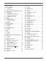
1
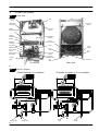
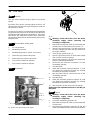
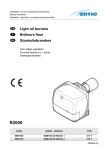
Wall hung, fan flue, room sealed gas boiler
GAIA
Service manual
Leave this manual adjacent to the gas meter
Models:
424 S
428 S
424 RS
BIASI S.p.A.
37135 Verona (Italy)
Via Leopoldo Biasi, 1
Stabilimento:
33170 Pordenone (Italy)
Via Pravolton, 1/B
Table of contents
1 Overall information . . . . . . . . . . . . . . . . . . . . .
1.1
Overall View . . . . . . . . . . . . . . . . . . . . . . . . .
1.2
Hydraulic diagram . . . . . . . . . . . . . . . . . . . .
1
1
1
2 General access and emptying hydr. circuits
2.1
Nomenclature . . . . . . . . . . . . . . . . . . . . . . . .
2.2
Body panels . . . . . . . . . . . . . . . . . . . . . . . . .
2.3
Access to the electric parts of the
control panel . . . . . . . . . . . . . . . . . . . . . . . . .
2.4
Access to the sealed chamber . . . . . . . . .
2.5
Emptying the main circuit . . . . . . . . . . . . .
2.6
Emptying the d.h.w. circuit . . . . . . . . . . . .
2
2
2
3 Diagrams . . . . . . . . . . . . . . . . . . . . . . . . . . . . . .
3.1
Wiring diagram . . . . . . . . . . . . . . . . . . . . . . .
3.2
Functional flow diagrams . . . . . . . . . . . . . .
3.3
Control circuit voltages . . . . . . . . . . . . . . . .
4
4
5
7
4
Fault finding . . . . . . . . . . . . . . . . . . . . . . . . . . . .
8
5 Main heat exchanger . . . . . . . . . . . . . . . . . . . .
5.1
Characteristics . . . . . . . . . . . . . . . . . . . . . . .
5.2
Removal . . . . . . . . . . . . . . . . . . . . . . . . . . . .
5.3
Cleaning . . . . . . . . . . . . . . . . . . . . . . . . . . . .
11
11
11
11
3
3
3
3
6 D.h.w. heat exchanger . . . . . . . . . . . . . . . . . . . 12
6.1
Function . . . . . . . . . . . . . . . . . . . . . . . . . . . . . 12
6.2
Removal . . . . . . . . . . . . . . . . . . . . . . . . . . . . 12
7 Pump . . . . . . . . . . . . . . . . . . . . . . . . . . . . . . . . . .
7.1
Function . . . . . . . . . . . . . . . . . . . . . . . . . . . . .
7.2
Checks . . . . . . . . . . . . . . . . . . . . . . . . . . . . .
7.3
Removal . . . . . . . . . . . . . . . . . . . . . . . . . . . .
13
13
13
13
8 Diverter valve and d.h.w. pressure switch .
8.1
Function . . . . . . . . . . . . . . . . . . . . . . . . . . . . .
8.2
Checks . . . . . . . . . . . . . . . . . . . . . . . . . . . . .
8.3
Removal . . . . . . . . . . . . . . . . . . . . . . . . . . . .
14
14
14
14
9 Electronic control circuit . . . . . . . . . . . . . . . .
9.1
Function . . . . . . . . . . . . . . . . . . . . . . . . . . . . .
9.2
Selection and adjustment devices . . . . . .
9.3
Checking the temperature . . . . . . . . . . . . .
9.4
Function selectors . . . . . . . . . . . . . . . . . . . .
9.5
Ignition gas pressure regulator . . . . . . . . .
9.6
Max. c/h power regulator . . . . . . . . . . . . . .
9.7
Checks . . . . . . . . . . . . . . . . . . . . . . . . . . . . .
9.8
Removal of the control circuit . . . . . . . . . .
9.9
Thermal control in the ” ”mode . . . . . . .
9.10 Thermal control in the ” ”mode . . . . . . .
17
17
17
17
18
19
19
19
19
21
21
10 Display circuit . . . . . . . . . . . . . . . . . . . . . . . . . .
10.1 Function . . . . . . . . . . . . . . . . . . . . . . . . . . . . .
10.2 Display circuit operation . . . . . . . . . . . . . . .
10.3 Removal . . . . . . . . . . . . . . . . . . . . . . . . . . . .
22
22
22
22
11 Full sequence ignition device . . . . . . . . . . . .
11.1 Function . . . . . . . . . . . . . . . . . . . . . . . . . . . . .
11.2 Checks . . . . . . . . . . . . . . . . . . . . . . . . . . . . .
11.3 Removal . . . . . . . . . . . . . . . . . . . . . . . . . . . .
11.4 Ignition sequence . . . . . . . . . . . . . . . . . . . .
23
23
23
23
24
12 Gas valve . . . . . . . . . . . . . . . . . . . . . . . . . . . . . .
12.1 Function . . . . . . . . . . . . . . . . . . . . . . . . . . . . .
12.2 Nomenclature of the parts . . . . . . . . . . . . .
12.3 Adjustment . . . . . . . . . . . . . . . . . . . . . . . . . .
12.4 Checks . . . . . . . . . . . . . . . . . . . . . . . . . . . . .
12.5 Removal . . . . . . . . . . . . . . . . . . . . . . . . . . . .
25
25
25
25
25
26
13 Main circuit flow switch . . . . . . . . . . . . . . . . .
13.1 Function . . . . . . . . . . . . . . . . . . . . . . . . . . . . .
13.2 Checks . . . . . . . . . . . . . . . . . . . . . . . . . . . . .
13.3 Removal . . . . . . . . . . . . . . . . . . . . . . . . . . . .
27
27
27
28
14 D.h.w. filter and flow limiter . . . . . . . . . . . . . .
14.1 General notes . . . . . . . . . . . . . . . . . . . . . . . .
14.2 Removal of the filter . . . . . . . . . . . . . . . . . . .
14.3 Flow limiter . . . . . . . . . . . . . . . . . . . . . . . . . .
29
29
29
29
15 Temperature probes . . . . . . . . . . . . . . . . . . . .
15.1 Function . . . . . . . . . . . . . . . . . . . . . . . . . . . . .
15.2 Checks . . . . . . . . . . . . . . . . . . . . . . . . . . . . .
15.3 Removal . . . . . . . . . . . . . . . . . . . . . . . . . . . .
30
30
30
31
16 By -- pass valve . . . . . . . . . . . . . . . . . . . . . . . . . 32
16.1 Function . . . . . . . . . . . . . . . . . . . . . . . . . . . . . 32
16.2 Removal . . . . . . . . . . . . . . . . . . . . . . . . . . . . 32
17 Water pressure switch and pump relè . . . .
17.1 Function . . . . . . . . . . . . . . . . . . . . . . . . . . . . .
17.2 Checks . . . . . . . . . . . . . . . . . . . . . . . . . . . . .
17.3 Removal of the pressure switch . . . . . . . .
17.4 Removal of the pump relè . . . . . . . . . . . . .
33
33
33
33
33
18 Flue fan, venturi, air pressure switch . . . . .
18.1 Function . . . . . . . . . . . . . . . . . . . . . . . . . . . . .
18.2 Checks . . . . . . . . . . . . . . . . . . . . . . . . . . . . .
18.3 Removal of the fan . . . . . . . . . . . . . . . . . . . .
18.4 Removal of the air pressure switch . . . . .
34
34
34
35
35
19 Ignition and detection electrodes . . . . . . . .
19.1 Function . . . . . . . . . . . . . . . . . . . . . . . . . . . . .
19.2 Checks . . . . . . . . . . . . . . . . . . . . . . . . . . . . .
19.3 Removal . . . . . . . . . . . . . . . . . . . . . . . . . . . .
36
36
36
36
20 Safety thermostat . . . . . . . . . . . . . . . . . . . . . . .
20.1 Function . . . . . . . . . . . . . . . . . . . . . . . . . . . . .
20.2 Checks . . . . . . . . . . . . . . . . . . . . . . . . . . . . .
20.3 Removal . . . . . . . . . . . . . . . . . . . . . . . . . . . .
37
37
37
38
21 Short spare parts list . . . . . . . . . . . . . . . . . . . . 40
1
Overall information
1.1
Overall View
Automatic
air release
valve
Fan
Expansion
vessel
Main heat
exchanger
Air pressure
switch
Safety
thermostat probe
Ignition
electrodes
Combustion
chamber
Burner
D.h.w.
heat exchanger
Detection
electrode
Gas valve
Pump
Diverter valve
D.h.w.
outlet
D.h.w.
inlet
D.h.w. temp
probe
C/h
flow
D.h.w. temp.
probe
Main circuit
flow switch
Full seq.
ignition device
Control
panel
Front view
C/h
return
Gas inlet
Rear view
fig. 1
1.2
Hydraulic diagram
Central hetaing (c/h) operation
C/h
water supply
C/h
water return
Domestic hot water (d.h.w.) operation
D.h.w.
inlet
D.h.w.
outlet
fig. 2
1
2
General access and emptying
hydraulic circuits
2.1
Nomenclature
1
6
2
A
fig. 4
3
To remove the side panels loosen the screws B (fig. 5),
bring the base of the panels far from the boiler and lift
them, freeing them from the side hooks of the frame.
To remove the lower protection plate completely unscrew the screws B and remove the plate (fig. 5).
5
4
fig. 3
1
Right side panel
2
Front panel
3
Lower protection plate
4
Control panel
5
Case lid
6
Left side panel
2.2
Body panels
Warning: isolate the boiler from the mains
electricity supply before removing any
covering or component.
B
B
fig. 5
To gain access to the supply terminal block and to the
parts located behind the control panel unscrew the
screws C and lower the panel (fig. 6).
For the most part of the check and maintenance operations it is necessary to remove one or more panels of
the case.
The side panels can be removed only after the removal
of the front panel.
C
To remove the front panel remove the two screws A
(fig. 4) and bring the base of the panel far from the
boiler.
Lift the front panel freeing it from the hooks placed on
its left and right side.
2
fig. 6
C
General access and emptying hydraulic circuits
2.3
Access to the electric parts of the control
panel
Warning: isolate the boiler from the mains
electricity supply before removing any
covering or component.
To gain access to the parts located inside the control
panel remove the four screws D (fig. 7) and remove the
cover pulling it towards the front.
F
fig. 9
2
Open the draining tap G (fig. 10) until the boiler is
completely emptied.
H
D
G
fig. 7
2.4
Access to the sealed chamber
To gain access to the parts contained in the sealed
chamber it is necessary to remove the cover of the
sealed chamber.
For this purpose, remove the front panel of the case and
remove the screws E as indicated in fig. 8.
fig. 10
E
To facilitate the downflow of water, remove the front
panel, also remove the sealed chamber cover and
loosen the nut H (fig. 10) of the automatic air bleed
valve.
Tight it again once the emptying has been completed.
2.6
E
Emptying the d.h.w. circuit
1
Close the d.h.w. circuit cut---off valve I (fig. 11);
2
Open one or more hot water taps of the plant until
the boiler has been completely emptied.
fig. 8
2.5
1
Emptying the main circuit
Close the c/h circuit isolation valves F (fig. 9).
I
fig. 11
3
Fan
Shutdown
lamp
b
bk
b
b
br
br
NC
COM
NO
w
br
b
gy
bk
COM
NO
r
COM
bk
r
r
bk
K1
w
w
b
br
g/y
g/y
b
gy
br
bk
br
br
br
b
br
b
r
bk
b
br
w
Display circuit
type 10.81
b
br
g/y
Ignition and flame
control device
NC
bk
M
~
b
gy
br
NO
NC
Water pressure
switch
Low limit
(brown plug)
bk
bk
Reset push
button
Water pressure
switch
High limit
(red plug)
br
Safety
thermostat
b
Ignition Flame detection
electrodes
electrode
Air pressure
switch
r
Wiring diagram
gy
b
bk
w
3.1
gy
b
Diagrams
b
3
K2
b
bk
bk
br
r
bk
g/y
Control circuit
type 10.80
bk
bk
gy
b
w
r
Pump
relay
bk
w
b
bk
bk
gy
b
br
g/y
bk
w
b
Domestic hot
water NTC
t
Central heating
NTC
Domestic hot Circulator
water pressure
switch
Electric supply connection
Frostat
1
3
bk
w
1
2
w
r
br = brown
Room thermostat
1
b = blue
bk = black
L
w = white
Power line
N
r = red
gy = grey
GND
y = yellow
g/y = green/yellow
* --- direct connection with the ignition and flame control device
4
br
b
Central heating
pressure
switch
br
b
bk
w
Gas valve
t
M
~
M1
M2
3
4
*
bk
r
gy
bk
bk
r
bk
w
br
b
g/y
Time switch
Diagrams
3.2
Functional flow diagrams
General layout
function switch position off
J4--- 1
F2 (1,6 A T)
PTC
A
N --- NEUTRAL
ACTIVE CIRCUIT
INACTIVE CIRCUIT
TRANSFORMER
N
S1
FUNCTION
SWITCH
L
L --- LINE
21V=
K1 (RELAY)
12V=
TO THE CONTROL
CIRCUIT’
S LOW
VOLTAGE
SECTION
J4--- 4
IGNITION
DEVICE
B
K2 (RELAY)
J4--- 3
J4--- 5
C
J3--- 7
N
J3--- 8
CENTRAL HEATING
PRESSURE
SWITCH
J4--- 6
J3--- 2
A Time switch
B: Room thermostat (jumper shown)
C:Frostat (jumper shown)
J3--- 3
PUMP
N
Function switch position
Heat request on c/h
J4--- 1
PTC
A
TRANSFORMER
N
S1
FUNCTION
SWITCH
L
F2 (1,6 A T)
21V=
K1 (RELAY)
12V=
TO THE CONTROL
CIRCUIT’
S LOW
VOLTAGE
SECTION
J4--- 4
IGNITION
DEVICE
B
J4--- 3
K2 (RELAY)
J4--- 5
J3--- 7
N
J3--- 8
C
CENTRAL HEATING
PRESSURE
SWITCH
J4--- 6
A Time switch
B: Room thermostat (jumper shown)
C:Frostat (jumper shown)
J3--- 2
J3--- 3
PUMP
N
5
Diagrams
Function switch position
Heat request on d.h.w.
J4--- 1
F2 (1,6 A T)
A
N --- NEUTRAL
ACTIVE CIRCUIT
INACTIVE CIRCUIT
TRANSFORMER
PTC
N
S1
FUNCTION
SWITCH
L
L --- LINE
21V=
K1 (RELAY)
12V=
TO THE CENTRAL
CIRCUIT’
S
LOW VOLTAGE
SECTION
J4--- 4
IGNITION
DEVICE
(or gas valve)*
B
K2 (RELAY)
J4--- 3
J4--- 5
C
J3--- 7
N
J3--- 8
CENTRAL HEATING
PRESSURE
SWITCH
J4--- 6
J3--- 2
A Time switch
B: Room thermostat (jumper shown)
C:Frostat (jumper shown)
J3--- 3
PUMP
N
Function switch position
Heat request on d.h.w.
J4--- 1
F2 (1,6 A T)
PTC
A
TRANSFORMER
N
S1
FUNCTION
SWITCH
L
21V=
K1 (RELAY)
12V=
TO THE CONTROL
CIRCUIT’
S
LOW VOLTAGE
SECTION
J4--- 4
IGNITION
DEVICE
B
J4--- 3
C
K2 (RELAY)
J4--- 5
J3--- 7
N
J3--- 8
CENTRAL HEATING
PRESSURE
SWITCH
J4--- 6
A Time switch
B: Room thermostat (jumper shown)
C:Frostat (jumper shown)
6
J3--- 2
J3--- 3
PUMP
N
Diagrams
3.3
Control circuit voltages
230 V~
network
C/h
flow switch
230~
0
0
Room
thermostat
230~
K1
230~
0
230~
D.h.w.
0
C/h
230~
K2
230~
Ignition device
D.h.w.
flow switch
a
16=
a
a
16=
a
0
15=
Electronic control circuit
Circulator
Main circuit
temperature
probe
D.h.w.
temperature
probe
a: never zero (short circuit) never 12V= (open circuit)
Modulating
operator
Electronic control circuit
Ignition
device
0
0
0
Air pressure switch
0
100~
Shut--- down lamp
and reset button
230~
0
Overheat thermostat
230~
Fan
b
gy
br
bk
br
br
br
b
r
bk
Electronic control circuit
Electrical voltages in Volts during normal operation with burner on at maximum power
7
Defect
#
Lockout lamp (red) on.
By pressing the reset push--- button
the boiler starts the ignition cycle.
The burner doesn’
t light on , the ignition sparks continue and the boiler
locks again.
J
J
Lockout lamp (red) on.
By pressing the reset push--- button
the boiler starts the ignition cycle.
The burner lights on , the ignition
sparks continue and the boiler locks
again.
J
J
J
The boiler does not start either in c/h
or d.h.w.. mode.
Fan still.
“Boiler on”light (green) on.
Main circuit pressure light red on
Lockout lamp (red) off.
Lockout lamp (red) on.
By pressing the reset push--- button
the boiler turns on and operates correctly.
J
D.h.w. circuit
J
Pump (windings)
J
Pump (rotor --- impeller)
J
Fuse (regulation p.c.b.)
J
Regulation p.c.b.
J
J
Full sequence device
J
J
Gas valve (on--- off operators)
J
Gas valve (modulating operator)
J
(6)
Main circuit flow switch
J
D.h.w. filter
Diverter valve (deviation group)
D.h.w. heat exchanger
15.2
J
J
Main circuit temp. probe
13.2 14.2
J
D.h.w. temp. probe
12.4
16
J
(5)
By--- pass valve
11.2
18.2
J
J
Fan and venturi device
9.7
J
J
Air pressure switch
8.2
19.2
J
J
Ignition electrode
7.2
J
Detection electrode
6
20.2
J
Safety thermostat
--(4)
C.h. circuit
The boiler does not start either in c/h
or d.h.w.. mode.
Fan still.
“Boiler on”light (green) on.
Main circuit pressure light green on
Lockout lamp (red) off.
J
--(1)
Power supply line
J
--(2)
Gas supply line
The boiler does not start either in c/h
or d.h.w. mode.
Fan still.
”boiler on”light (green) off.
Lockout lamp (red) off.
--(3)
Flue pipes
Section of the manual !
(note ref. in brackets)
--(7)
Injectors
J
J
--(8)
Expansion vessel
Components to check
---
Safety valve
Fault finding
17
J
Water pressure switch
4
J
Pump relay
8
Function selectors (reg. p.c.b)
D.h.w. pressure switch
Diverter valve (membrane)
Defect
#
C.h. circuit
J
Pump (windings)
J
Pump (rotor --- impeller)
J
J
Diverter valve (deviation group)
Diverter valve (membrane)
D.h.w. heat exchanger
D.h.w. circuit
J
J
J
The boiler does not supply d.h.w.
(cold water from the tap).
Regular operation in c/h mode even
during a drawing off d.h.w.
On c/h mode the temperature of the
main circuit reaches 90°C and the c/h
system does not heat.
The boiler operates correctly on d.h.w.
mode.
J
J
With the function switch in summer or
winter mode the boiler turns on even
without drawing the d.h.w. and the
main circuit temperature is kept at
about 90°C.
The pump runs continuously.
The c/h system does not heat.
The boiler operates correctly in d.h.w.
mode.
Noisy boiler
The boiler turns off immediately,drawing d.h.w.
Regular functioning in c/h
The fan turns but the boiler does not
turn on.
The boiler fires on c/h and d.h.w. for a
few seconds, goes off and fires again
constantly.
J
J
J
J
J
J
J
J
J
D.h.w. pressure switch
The boiler switches on and off the
burner to a fixed gas pressure
Fuse (regulation p.c.b.)
J
Function selectors (reg. p.c.b)
J
J
Full sequence device
J
Gas valve (modulating operator)
J
J
J
Main circuit flow switch
J
D.h.w. filter
J
J
D.h.w. temp. probe
Main circuit temp. probe
Gas valve (on--- off operators)
16
By--- pass valve
15.2
18.2
J
J
J
Fan and venturi device
13.2 14.2
J
Air pressure switch
12.4
19.2
Ignition electrode
11.2
20.2
--(8)
Expansion vessel
--(7)
Injectors
Components to check
Detection electrode
9.7
Safety thermostat
8.2
---
Safety valve
7.2
17
Water pressure switch
6
Pump relay
--(4)
Regulation p.c.b.
Incorrect modulation
J
Power supply line
J
----(1) (2)
Gas supply line
The boiler runs but the combustion is
noisy and there is flame lift effect.
--(3)
Flue pipes
Section of the manual !
(note ref. in brackets)
Fault finding
9
C.h. circuit
Check for 220--- 240V~ between line (L) and neutral (N)
Verify the integrity of supply cable, plug and external fuses.
Check the polarity of line and neutral connection
Verify the soundness of the gas supply pipe, the position of
stop valves.
Check the gas pressure at the inlet test point of the gas valve
(see sect. 12.3) with the boiler at rest and during operation
1
2
Note
Water leaks from the safety valve
when the boiler is off.
Water leaks from the safety valve during operation on c/h
Low flow rate of d.h.w.
J
D.h.w. circuit
J
D.h.w. heat exchanger
J
J
3
5
4
Gas valve (modulating operator)
J
J
Main circuit flow switch
Gas valve (on--- off operators)
Full sequence device
Function selectors (reg. p.c.b)
Diverter valve (membrane)
Pump (rotor --- impeller)
Pump (windings)
and compare it with the values given on the installation
booklet.
Check for soundness and absence of obstructions. Verify
that the flue terminal is correctly installed (see clearances)
and ensure that exhaust gas is not sucked back by the
boiler.
Check for soundness of the circuit and verify its correct filling
(see also installation manual).
A jammed by--- pass could cause the over--- heating of the
main circuit and the intervention of the safety thermostat.
J
Diverter valve (deviation group)
J
Power supply line
J
D.h.w. pressure switch
Poor d.h.w. temperature
Fuse (regulation p.c.b.)
J
Gas supply line
Defect
#
D.h.w. filter
J
J
(9)
18.2
19.2
20.2
---
9
d.h.w. pressure too high or flow rate too high. If necessary
insert a flow rate limiter (14.3).
Check the pressurization of the expansion vessel. Refer to
the installation manual for proper values.
8
J
J
Verify the cleanness of injectors.
J
J
17
7
J
J
--(8)
--(7)
Check the minimum gas pressure at the outlet test point of
the gas valve (see sect. 12.3) and compare it with the value
given on the installation booklet.
Main circuit temp. probe
16
Injectors
6
D.h.w. temp. probe
15.2
By--- pass valve
13.2 14.2
Fan and venturi device
12.4
Air pressure switch
11.2
Expansion vessel
Components to check
Ignition electrode
9.7
Detection electrode
8.2
Safety thermostat
7.2
Safety valve
6
Water pressure switch
--(4)
Regulation p.c.b.
The boiler operates correctly but the
gas pressure to the burner remains at
minimum.
--(3)
Flue pipes
----(1) (2)
Pump relay
10
Section of the manual !
(note ref. in brackets)
Fault finding
5
Main heat exchanger
5.1
Characteristics
D
E
B
The main heat exchanger (A in fig. 12) has the function
of transferring heat of the gas produced by combustion to the water circulating in it.
fig. 14a
A
For model 428 S...
4b Remove the front part of the flue gas hood by unscrewing the four screws C (fig. 14b)
5b Remove the cover of the combustion chamber
D
E
C
fig. 12
The hydraulic circuit consists of five elliptic pipes connected together in series (fig. 13).
fig. 14b
6
Unscrew the automatic air valve connection nut
D and remove the valve (fig. 14a);
7
Separate the heat exchanger from the hydraulic
circuit, loosening the inlet and outlet pipe fittings;
For models 424 S, 424 RS...
fig. 13
5.2
8a
Removal
For model 428 S...
Warning: isolate the boiler from the mains
electricity supply before removing any
covering or component.
8b
9
1
Empty the main circuit of the boiler
10
2
Remove the front panel of the case
3
Remove the sealed chamber cover.
For models 424 S, 424 RS...
4a
Remove the cover of the combustion chamber;
5a
Remove the front part of the flue gas hood by unscrewing the screw B (fig. 14a)
move the right pipe and free the right connection;
lower the right side of the exchanger and extract
it from the front;
5.3
Extract the heat exchanger, from the front;
Unscrew the pipe E (fig. 14b) from the heat exchanger;
Assemble the heat exchanger carrying out the removal operations in reverse sequence.
Cleaning
If there are deposits of soot or dirt between the blades
of the heat exchanger, clean with a brush or non---metallic bristle brush.
In any case, avoid any actions that can damage the protective varnish with which the exchanger has been covered.
11
6
D.h.w. heat exchanger
2
6.1
Function
3
The d.h.w heat exchanger (A in fig. 15) allows the instantaneous transferral of heat from the primary hydraulic circuit to the water destined for d.h.w use.
Remove the front panel of the case and lower the
instrument panel
Completely unscrew the two Allen key screws B
(in fig. 17 the right one is shown) which hold the
exchanger to the brass deviator groups;
A
B
fig. 15
The schematic structure is shown in fig. 16.
fig. 17
4
Primary hydraulic circuit
Reassemble the d.h.w. heat exchanger carrying out the
removal operations in the reverse order.
Attention. Reassembling the exchanger be sure to
put the off center location/securing pin indicated in
fig. 18 towards the left side of the boiler.
Domestic hot water circuit
fig. 16
6.2
Removal
Warning: isolate the boiler from the mains
electricity supply before removing any
covering or component.
1
12
Empty the primary circuit and the d.h.w circuit of
the boiler
Move the exchanger towards the rear side of the
boiler and extract it.
fig. 18
7
Pump
n
7.1
Function
With the boiler off remove the front panel and lower the
control panel;
The pump (A in fig. 19) has the function of making the
water in the main circuit circulate through the main heat
exchanger and therefore through the c/h system (during the c/h function) or through the secondary heat exchanger (during the d.h.w. function).
Note: the pump can be stopped by the intervention of
the low limit water pressure switch.
Check the absence of starting defects.
for Myson pump: unscrew the plug of the pump by hand
(the plug cannot be removed). Pull it and turn the rotor.
Start the boiler and verify if the motor runs.
for Salmson pump (high head alternative): remove the
air release screw of the pump. Start the boiler and with
a screwdriver, have the rotor turn in the direction of the
arrow. If there is a defect in starting, the rotor will begin
to turn normally only starting it manually.
n
Check that the impeller is integral with the rotor.
Remove the pump head loosing the screws which hold
it to the pump body and check that the impeller is firmly
jointed with the rotor.
7.3
A
Warning: isolate the boiler from the mains
electricity supply before removing any
covering or component.
If the clearance to the right side of the boiler is restricted, the removal of the pump can be easily
achieved by first removing the head by unscrewing
the four Allen keys screws (B in fig. 21, the two on
the upper side indicated).
fig. 19
7.2
Checks
Warning: isolate the boiler from the mains
electricity supply before removing any
covering or component.
n
Check that the pump is not seized and that the
movement of the rotor is not subject to mechanical impediments.
With the boiler off, remove the front panel and lower the
instrument panel. Remove the air release plug of the
pump and turn the rotor with a screwdriver.
1
Empty the main circuit of the boiler.
2
Remove the front panel of the case, the right side
panel and lower the control panel.
3
Disconnect the connector C (fig. 21).
4
Completely unscrew the connection nuts D and
remove the pump.
5
Before the reassembling, carefully clean the support seat of the gasket.
6
Reassemble the pump carrying out the removal
operations in the reverse order.
Check the electrical completeness.
n
Removal
Remove the service panel, disconnect the connector to
the electronic control circuit (see electrical diagram)
and measure the electrical resistance between the
pump supply conductors. (fig. 20).
D
Electrical resistance of the windings (at ambient temperature) on switch position 3 must be about:
210
180
220
120
O
O
O
O
---------
Myson CP53
Myson CP63 (high head alternative)
Salmson MYE30
Salmson MYL50 (high head alternative)
B
C
Connector
O
fig. 20
b
br
g/y
b
br
g/y
M
~
D
fig. 21
13
8
Diverter valve and d.h.w.
pressure switch
8.1
Function
V=
K1
The diverter valve (A in fig. 22) has the function of modifying the hydraulic circuit of the boiler by means of an
hydraulic command given by the opening of a d.h.w.
tap in order to send the water that exits the main heat
exchanger towards the c/h system or towards the
d.h.w. heat exchanger.
K2
Moreover it operates the d.h.w. pressure switch which
acts on the electronic control circuit.
fig. 23
n
1
A
2
3
Check the mechanical function
Switch off the boiler; remove the front panel of the
case, the lower protection plate and lower the
control panel.
Remove the pressure switch as explained in the
section 8.3 “Removal of the switch“.
Open and close a d.h.w. tap and verify the position of the shaft B referring to fig. 24.
B
D.h.w. tap OPEN
fig. 22
8.2
n
Checks
General check
It is possible to verify the general operation of the valve
by measuring the voltage between the leads of the
d.h.w. pressure switch during the operation on c/h and
d.h.w.
Warning: isolate the boiler from the mains
electricity supply before removing any
covering or component.
D.h.w. tap CLOSED
fig. 24
8.3
Warning: isolate the boiler from the mains
electricity supply before removing any
covering or component.
1
Switch off the boiler and open the control panel.
2
Connect a meter, set for direct voltage measurement, to the points indicated in fig. 23.
n
1
3
Switch the boiler on position and verify the voltages during c/h and d.h.w. by matching the readings with the values indicated in the section 3.3.
2
14
Removal
Removal of the membrane
Remove the front panel of the case, lower the control panel and empty the d.h.w. circuit.
Remove the forks C and move away the pipes D.
(fig. 25 --- rear view of the boiler).
Diverter valve and d.h.w. pressure switch
D
Assembling the part, ensure to place the concave
side of the membrane towards the actuator plate I
(fig. 27).
When fixing the actuator to the valve, fit the reference shaft J in the seat of the valve (fig. 28).
C
fig. 25
Loose the screws E and remove the hydraulic
actuator F (fig. 26).
3
E
J
fig. 28
F
n
Removal of the switch
1
Switch off the boiler; remove the front panel of the
case, the lower protection plate and lower the
control panel.
Remove the fork K that holds the d.h.w. pressure
switch L placed on the right side of the valve and
remove the switch (fig. 29).
Open the box and disconnect the switch.
2
E
3
4
fig. 26
4
Unscrew the six screws G, open the hydraulic
actuator and remove the membrane H. (fig. 27).
Reassemble the switch proceeding in the reverse
order.
L
G
K
H
fig. 29
n
Removal of the valve and the diverter mechanism
1
Switch off the boiler; remove the front panel of the
case, the lower protection plate and lower the
control panel.
Drain the d.h.w. and the c/h circuits.
I
2
fig. 27
5
Assemble the part proceeding in reverse order.
3
Completely loosen the connections to the hydraulic circuits indicated in fig. 30.
15
Diverter valve and d.h.w. pressure switch
7
Unscrew the screw R that holds the d.h.w. heat
exchanger, the bolt S that holds the valve to the
frame (fig. 33) and remove the valve.
fig. 30
4
Remove the forks M and move away the pipes N
(fig. 31).
R
N
S
M
fig. 33
fig. 31
5
6
Remove the forks that hold the d.h.w. pressure
switch O and the main circuit flow switch P and
separate the switches from the valve (fig. 32).
Disconnect the temperature probe Q.
Q
The diverter mechanism is composed by two parts. To
reach them remove the hydraulic actuator as explained
at the step 3 of the part Removal of the membrane of this
chapter.
With a suitable spanner unscrew both plugs indicated
in fig. 34 and remove the parts of the diverter mechanism.
O
P
fig. 34
fig. 32
16
Reassemble the valve proceeding in the reverse order.
9
Electronic control circuit
9.1
Function
Several of these devices are directly accessible by the
user (function switch, temperature adjustment potentiometers etc.) others are accessible by removing the
cover.
Inlet Information
1
d.h.w. temperature probe
main circuit temperature probe
d.h.w. pressure switch
c/h flow switch
2
function switch
d.h.w. temperature reg.
c/h temperature reg.
function selectors
max. c/h power reg.
ignition gas pressure reg.
room thermostat
3
4
5
6
9
8
7
fig. 36
Outlet command
Flame ignition---control device
Gas modulator
Pump
fig. 35
The fundamental function of the control circuit is that of
controlling the boiler in relation to the external needs
(heating the room, heating the water for d.h.w. use) operating in order to keep the temperature of the hydraulic
circuits constant.
This is obviously possible within the useful power and
maximum working temperature limits foreseen.
Generally, the control circuit receives inlet information
coming from the boiler (the sensors) or from the outside
(knobs, room thermostat, etc.), processes them and
consequently acts with outlet commands on other
components of the boiler (fig. 35).
9.2
Selection and adjustment devices
On the control circuit several selection, adjustment and
protection devices are located. (fig. 36).
1
2
3
4
5
6
7
8
9
9.3
function switch
fuse F2 (1,6 A)
K1 relay
K2 relay (ignition device control)
d.h.w. temperature reg. potentiometer
function selectors
c/h maximum power adjustment (RISC.)
ignition gas pressure adjustment (ACC.)
c/h temperature reg. potentiometer
Checking the temperature
The control circuit makes it possible to separately adjust the c/h water flow and d.h.w. outlet temperature.
The temperature of the water is converted into an electric signal by means of temperature probes.
The user, setting the desired temperature with the
knobs of the instrument panel operates the variable elements (5 and 9 in fig. 36) of the control circuit.
If the power requested is lower by about 40% of the
maximum useful output, the control is done by igniting
at the minimum power and turning off the burner (on--off function). If the power is higher the boiler will modulate down to 40% of its maximum power output.
When the boiler functions in c/h (fig. 37), the signal
coming from the primary temperature probe is compared to the signal given by the instrument panel
).
through the adjustment made by the user (knob
The result of such a comparison operates the modulation of the gas valve, consequently changing the instantaneous useful output of the boiler.
17
Electronic control circuit
9.4
Primary NTC
MR
Function selectors
The function selectors ”6” (fig. 36 and fig. 39) are
microswitches with which it is possible to select the various modes of functioning of the boiler.
4
Gas pressure calibration
Gas change
No function
ON (1)
OFF (0)
fig. 39
Central heating temperature
f
Selector 2
It selects the functioning of the boiler on the basis of the
type of gas used.
fig. 37
When the boiler functions in d.h.w. (fig. 38), the signal
coming from the d.h.w. temperature probe is compared
with the signal given by the instrument panel through
the adjustment made by the user (knob
).
US
Primary NTC
It allows the selection of the maximum supply current
given to the modulator device.
To set correctly the selector follow the table of fig. 40.
Gas supply
Position of selector
Approx. Max current
trough the modulator device
Natural gas
On
120 mA
L.P.G.
Off
165 mA
fig. 40
Gas
valve
Secondary
heat exchanger
Domestic hot water NTC
75 ° C
ES
f
Selector 3
It forces the functioning of the boiler in order to permit
the optimal gas pressure at the burner to be adjusted
during the ignition phase.
The adjustment (see section 9.5) is done by means of
the potentiometer ”8”marked “
ACC”(fig. 36).
After the adjustment operations bring the selector back
to the normal position (ON).
ON--OFF
adjustment
Modulating
adjustment
Gas
inlet
ON (1)
Domestic hot water
temperature
fig. 38
Normally, the result of the comparison between these
two signals directly operates the adjustment elements
of the gas valve, adjusting the useful output generated
in order to stabilize the temperature of the exiting water.
Normal
The control sequences in function and in function
are illustrated in detail in sections 9.9 and 9.10.
OFF (0)
gas pressure calibration
fig. 41
f
Selector 4
It makes it possible to select the minimum time that
must pass between two ignitions of the burner in c/h
function.
If during the functioning in d.h.w. mode, the temperature of the primary circuit goes over 75°C, the useful
output is automatically reduced so that the primary circuit cannot reach excessive temperatures.
18
3
RR
ON--OFF
adjustment
modulating
adjustment
gas
inlet
2
6
Reignition delay
1
In fig. 39 the selectors are illustrated in the configuration in which the p.c.b. is set in the factory (natural gas
boiler).
Gas
valve
ON (1)
3 min.
fig. 42
OFF (0)
none
Electronic control circuit
9.5
Ignition gas pressure regulator
By using the device ”8”(fig. 36) marked “
ACC.”on the
circuit board, it is possible to adjust the gas pressure at
the injectors in the ignition phase.
F2
(1,6 A)
This pressure is maintained at the injectors until ignition
occurs (ionization signal).
To carry out the adjustment move the function selector
nº3 downwards (adjustment) and use the adjustment
device ”8”(ACC).
Bring the gas pressure at the injectors to the value indicated in the tables ”data for gas adjustment”stated for
each model in the second part of the manual (ignition
pressure).
By rotating the device clockwise the pressure increases.
Check the regular ignition of the burner by turning the
boiler on and off repeatedly.
fig. 44
9.8
Removal of the control circuit
Warning: isolate the boiler from the mains
electricity supply before removing any
covering or component.
1
Remove the cover of the control panel as described in the section 2.3 of this manual;
2
Delicately flex the hooks indicated infig. 45 and
disconnect the four connectors A
After the adjustment operation move the selector upwards (normal).
ON (1)
Normal
D
OFF (0)
A
gas pressure calibration
fig. 43
fig. 45
9.6
Max. c/h power regulator
3
By using device 7 (fig. 36) marked “RISC.”on the circuit board, you can limit the maximum useful output delivered in the c/h function. This adjustment does not influence the maximum useful output delivered in d.h.w.
function.
C
By rotating the device clockwise the pressure increases.
9.7
n
unscrew the three screws B and move away the
bracket C (fig. 46);
B
Checks
Check that the fuse is complete
If the control circuit does not supply any device (pump,
gas valve, etc.) check that the fuse F2 is complete
(fig. 44).
The F2 fuse can be reached by removing the panel
cover.
If the fuse is blown replace it with one that has the same
characteristics after having identified the cause of the
interruption.
fig. 46
4
unscrew the three screws D and remove the circuit (fig. 45);
19
Electronic control circuit
5
assemble the control circuit following the disassembly procedures in the reverse order.
E
Attention: in order to facilitate the mounting of the
cover:
1
F
position the knobs of the panel as illustrate in
fig. 47;
fig. 48
4
position the spindles as in fig. 49 and mount the
panel cover.
After having installed the control panel make sure the
) and domestic hot water temperacentral heating (
ture ( ) adjustment knobs can move freely (half a turn).
fig. 47
2
insert the spindles in the potentiometers E and F
(fig. 48) and rotate them fully clockwise;
3
extract the spinldes and insert them with the flat
side pointing in the direction shown in fig. 48;
20
fig. 49
Electronic control circuit
9.9
Thermal control in the ” ”mode
Switch in the
function mode
Green LED on
See functioning with the function
switch in the
mode
(sec. 9.10)
YES
Taking
water from the domestic hot
water circuit?
Is primary circuit
temperature higher than that
selected?
YES
Request for heat from
room thermostat?
NO
Circulator off
Ignition device off
NO
NO
YES
Starts the circulator
Supplies the ignition device
fig. 50
9.10 Thermal control in the ” ”mode
Switch in the
YES
function mode
Taking
water from the domestic hot
water circuit?
NO
Circulator off
Ignition device off
Circulator on
YES
Supplies the ignition device
Is domestic
hot water outlet temperature
lower than that
required?
NO
Ignition device off
fig. 51
21
10
Display circuit
10.1
Function
The boiler is equipped with a pcb that displays some information about the operation of the appliance.
The electric signals that operate the display circuit are
given directly by the electronic control circuit or by the
water pressure switches.
Electronic control circuit
This light indicates the heat request signal from the
electronic control circuit and it comes on when the
water temperature (d.h.w. or c.h. circuit) is lower than
the requested on the control panel.
During d.h.w. operation it coincides with the ignition of
the burner.
During c.h. operation the light could be on and the
burner could remain off due to the room thermostat
and/or time switch that don’
t call for heat.
3
D.h.w. request --- green
This light comes on when the boiler operates on d.h.w.
4
Main circuit pressure --- yellow / green / red
These lights indicate the pressure of the water in the
main (c.h.) circuit.
If the left one (yellow) is on, this means that the pressure
is too low (approx. below 1 bar). If the right one (red)
comes on, the water pressure is too high (approx. over
2 bar).
High and low limit
water pressure switches
fig. 52
10.2
Display circuit operation
The following drawing (fig. 53) and list illustrate the
position of each light and its function.
The colours are referred to the transparent windows of
the control panel cover.
The central light (green) indicates the right pressure
and the correct filling of the circuit.
5
Main circuit temperature --- green / yellow
These lights indicate the water temperature in the main
(c.h.) circuit.
All the lights are green with the exception of the right
one that is yellow and indicates the highest temperature.
Only one at a time of these light is turned on.
The lights are turned on referring to the signal that
comes from the central heating temperature probe.
Consequently, the reading of the temperature can be
altered by a faulty temperature probe.
10.3
Warning: isolate the boiler from the mains
electricity supply before removing any
covering or component.
5
4
3
2
1
fig. 53
1
Boiler on --- green
1
Remove the cover of the control panel as described in the section 2.3 of this manual;
disconnect the connector A, remove the two
screws B (fig. 54) and remove the circuit board;
2
It indicates the operation of the boiler.
When the boiler is switched on, the indicator is continuously lit except after the extinction of the burner during
the c.h. operation.
In this condition the light flashes for a period of 3 minutes indicating the reignition delay state of the boiler.
This flashing indication is not affected by the position of
the function selector on the control circuit (see sect.
9.4).
Switching the boiler on, the light could remain switched
off for a period not longer than 20 seconds due to the
reset time of the control system.
2
Heat request --- green
22
Removal
B
A
fig. 54
3
assemble the circuit following the disassembly
procedures in the reverse order.
11
Full sequence ignition device
11.1
Function
The ignition and flame control device, type S4565DD,
used on electronic ignition boilers with forced flue gas
expulsion carries out the following fundamental functions:
f
does a sequence of operations (ignition cycle)
which lead to the ignition of the gas at the burner
f
checks the presence of the flame during the entire period in which it is activated
f
supplies the fan and checks its functioning by
means of the signal coming from the flue gas
pressure switch.
The ignition device is supplied by the electronic control
circuit when the ignition of the burner is requested.
The ignition device has a safety function and any incorrect interventions or tampering can result in conditions of dangerous functioning of the boiler.
The ignition device can lock the functioning of the boiler
(lock state) and stop its functioning up to the resetting
intervention. The lock is signalled by the ignition of the
lock lamp and the device can be reset only by using the
reset push---button placed on the instrument panel.
Some components which are connected to the device
that, can activate the lock state. The causes of a lock
state could be:
f
the intervention of the safety thermostat (primary
hydraulic circuit)
f
a fault on gas feeding
f
faulty ignition (ignition electrode, its wiring and
connection)
f
faulty flame detection (detection electrode, its wiring and connection)
f
gas injectors plugged
f
faulty gas valve (on---off operators) or not electrically supplied
f
faulty ignition device
While the burner is on, turn the gas supply off. The device should carry out a complete ignition cycle and then
shutdown.
When turning the boiler on and off with the function
switch, the device should not reset itself and the burner
should not turn on.
11.3
Removal
Warning: isolate the boiler from the mains
electricity supply before removing any
covering or component.
1
Remove the front panel of the case and lower the
control panel (see sect. 2.2);
2
unscrew the screw A and remove the protection
cover B; disconnect the flame detection cable C
and the ignition cable D (fig. 55);
C
D
B
A
fig. 55 (view from the left side of the boiler)
3
remove the cable clamp and disconnect the two
wires;
4
remove the ignition device by moving it from towards left (fig. 56);
other components like the flue gas pressure switch can
temporarily stop the ignition of the burner but allow its
ignition when the cause of the intervention has
stopped.
fig. 57 shows the sequence of the operations that are
carried out at the starting of every ignition cycle and
during normal functioning.
11.2
n
Checks
Shutdown sequence
Start the boiler until the burner is ignited.
fig. 56
23
Full sequence ignition device
11.4
Ignition sequence
Supply from the electronic control circuit
YES
Shutdown
memorised?
NO
Resets shutdown
NO
Fan pressure switch in
standby?
YES
Starts fan
Stops fan
Memorizes shutdown
Shutdown indicator light turns on
NO
Fan pressure switch
working?
YES
Wait time starts
Wait time starts
NO
NO
Fan pressure switch
working?
Presence
of flame?
YES
YES
YES
Waiting time
finished?
NO
Starts ignition sparks
Opens gas valve
Ignition time starts
NO
NO
Ignition time finished?
Presence
of flame?
YES
Closes gas valve
Stops fan
Stops ignition sparks
Memorizes shutdown
Turns shutdown indicator light on
YES
NO
Reset push button
pressed?
Stops ignition sparks
Gas valve open
YES
Closes gas valve
YES
YES
fig. 57
24
Presence of flame?
Fan pressure switch
working?
NO
NO
12
Gas valve
12.1
Function
5
The gas valve controls the gas inflow to the boiler
burner.
By means of an electric command given to the on---off
operators the passage of the gas through the valve can
be opened or closed.
By means of an electric command given to the modulating operator the pressure can be varied and therefore
the gas flow rate to the burner (modulation). The modulator device has mechanical organs which permit the
adjustment of the minimum and maximum pressure exiting the valve.
12.2
Nomenclature of the parts
1
On---off operators
2
Modulating operator
3
Modulating operator’
s electric connectors
4
Valve inlet gas pressure test point
5
Valve outlet gas pressure test point
6
Gas pressure maximum adjuster
7
Gas pressure minimum adjuster
12.3
4
fig. 59
Warning: isolate the boiler from the mains
electricity supply before removing any
covering or component.
1
2
3
4
5
6
7
8
Adjustment
9
5
3
10
11
12
Remove the front panel of the case and lower the
control panel as described in the section 2.2;
open the gas pressure tap ”4”at the valve input,
connect a gauge and check the gas pressure of
the supply network;
close the gas pressure tap ”4”;
open the gas pressure tap ”5”at the valve output
and connect a pressure gauge;
remove the protection cap from the mechanical
pressure adjustment elements;
disconnect one of the two connectors ”3”of the
modulating operator;
start the boiler;
rotate the minimum pressure adjuster “7”until
you obtain the espected pressure (by rotating
clockwise the pressure increases);
turn the boiler off and connect the wire to the
modulating operator;
start the boiler;
rotate the maximum pressure adjuster “6”until
you obtain the espected pressure (by rotating
clockwise the pressure increases);
turn the boiler off and disconnect the gauge;
At the end of the adjustment ensure to seal the gas
test point.
7
12.4
Warning: isolate the boiler from the mains
electricity supply before removing any
covering or component.
6
2
1
n
1
2
fig. 58 (view from the left side of the boiler)
Checks
Check the modulating operator coil
Remove the front panel of the case and lower the
control panel.
Disconnect one of the two connectors ”3”(fig. 58)
of the modulating operator and measure the elec-
25
Gas valve
trical resistance of the coil.
Its electrical resistance value must be approx.
125 O.
n
1
2
3
Check the modulating operator coil
Remove the front panel of the case and lower the
control panel.
Remove the full sequence ignition device (see the
section 11.3 of this manual).
Measure the electrical resistance between the
leads of the on---off operators as illustrated in
fig. 60.
1
Remove the front panel of the case and lower the
control panel.
2
Remove the full sequence ignition device (see the
section 11.3 of this manual).
3
Disconnect the modulating operator.
4
Unscrew the eight screws indicated in fig. 61 and
remove the valve.
5
Reassemble the valve carrying out the removal
operations in reverse order.
Upper
on---off
operator
approx. 1 260 O
Lower on---off
operator
approx. 3 000 O
fig. 60
12.5
Removal
Warning: isolate the boiler from the mains
electricity supply before removing any
covering or component.
26
fig. 61
13
Main circuit flow switch
13.1
Function
K2
K1
The main circuit flow switch (A in fig. 62) is a device that
controls the speed of water that crosses the main heat
exchanger.
V~
A
fig. 63
n
Mechanical function
1
Remove the front panel of the case and lower the
control panel as described in the section 2.2 of
this manual.
2
Remove the fork C that holds the main circuit flow
switch B (fig. 64).
fig. 62
This device controls the regular functioning of the
pump, the presence of water in the primary circuit of the
boiler and the absence of obstructions of the main heat
exchanger during the c/h function as well as during the
d.h.w. function.
As a consequence of any one of these causes the main
circuit flow switch cuts---off an electric circuit by means
of a microswitch (B in fig. 64) installed on it.
B
The main circuit flow switch is connected to the electronic control circuit and its intervention prevents or
stops the burner ignition cycle but does not send the
boiler in the lock state.
13.2
Checks
Warning: isolate the boiler from the mains
electricity supply before removing any
covering or component.
n
C
fig. 64
3
Start and stop the boiler in c/h operation (time
switch and external controls must call for heat)
and verify the position of the shaftD referring to
fig. 65
General check
It is possible to verify the general operation of the switch
by measuring the voltage between its leads during the
operation on c/h or d.h.w.
Warning: isolate the boiler from the mains
electricity supply before removing any
covering or component.
1
Switch off the boiler and open the control panel.
2
Connect a meter, set for alternating voltage
(230V) measurement, to the points indicated in
fig. 63.
3
Switch the boiler on position and verify the voltage by matching the readings with the values
indicated in the section 3.3.
Boiler OFF
D
Boiler ON
fig. 65
27
Main circuit flow switch
13.3
Removal
4
Warning: isolate the boiler from the mains
electricity supply before removing any
covering or component.
Removal of the membrane
n
1
Remove the front panel of the case, lower the control panel and empty the main circuit.
Remove the fork E that holds the main circuit flow
switch B (fig. 64).
Unscrew the four screws F, open the hydraulic
operator and remove the membrane G (fig. 66).
2
3
G
F
I
fig. 66
28
n
1
2
3
4
H
Assemble the part proceeding in reverse order.
Assembling the part, ensure to place the concave
side of the membrane towards the actuator plate H
and the reference hole indicated in the seat I
(fig. 66).
Removal of the switch
Switch off the boiler; remove the front panel of the
case, lower the protection plate and lower the
control panel.
Remove the fork C that holds the switch placed
on the valve and remove the switch (fig. 64).
Open the box and disconnect the switch.
Reassemble the switch proceeding in the reverse
order.
14
D.h.w. filter and flow limiter
14.1
General notes
The input port of the d.h.w. circuit is provided wit a net
filter and its function is to stop the passage of any impurities through the circuit.
The d.h.w. filter is located in the c.h. return group (indicated in fig. 67).
A
fig. 68
14.3
Flow limiter
424 S bolers are provided in the factory with a flow limiter rated at 10 litres/min.
If the flow rate of the d.h.w. circuit on the 428 S boiler
is too high, it is also possible to limit it installing a flow
limiter. The following sizes are available:
Nominal flow rate (litres/min)
Colour
10
Blue
12
Red
To install the flow limiter operate as in the following sequence:
1
Remove the d.h.w. filter as explained in the section 14.2.
2
Unscrew the part B (fig. 69) and remove it from
the body of the filter.
3
Install the flow limiter C putting its smaller diameter side towards the part B.
4
Install the filter following the removing sequence
in reverse order.
fig. 67
14.2
Removal of the filter
Warning: isolate the boiler from the mains
electricity supply before removing any
covering or component.
1
Remove the front panel of the case, the lower
protection plate, lower the control panel and
empty the d.h.w. circuit.
2
Unscrew the plug A (fig. 68) and extract the filter.
B
C
fig. 69
29
15
Temperature probes
15.1
Function
probe) A, (fig. 71 and fig. 72) one on its input, before
the pump (d.h.w. temperature probe) B (fig. 71 and
fig. 73).
The temperature probe has the function of converting
the temperature of the water of the hydraulic circuit
where it is installed into an electric signal (resistance).
The relation between temperature and electrical resistance is stated in fig. 70.
A
O
12500
12000
11500
11000
10500
B
10000
9500
9000
8500
8000
7500
c/h
flow
7000
6500
d.h.w.
water inlet
d.h.w.
water outlet
fig. 71
6000
5500
15.2
5000
n
4500
4000
Checks
Temperature ---resistance relationship
Warning: isolate the boiler from the mains
electricity supply before removing any
covering or component.
3500
3000
2500
2000
1500
1000
500
20 25
30
35 40
45
50 55
60
65 70
75
80 85
90
°C
95 100
fig. 70
In the boilers with mixed function (c/h + d.h.w.) two
temperature probes are assembled, one on the output
of the main heat exchanger (main circuit temperature
30
c/h
return
Disconnect the cable from the temperature probe.
Measure the temperature of the pipe near the temperature probe and check the electrical resistance according to the graph in fig. 70.
Remember that a temperature probe failed in short circuit sends a signal to the control circuit at a temperature
equivalent to 100°C. A disconnected or interrupted
temperature probe sends a signal at a temperature
equivalent 0°C thus the burner will always be on maximum power.
Temperature probes
15.3
Removal
Warning: isolate the boiler from the mains
electricity supply before removing any
covering or component.
To remove the main circuit or the d.h.w. temperature probes follow the same sequence.
Refer to fig. 72 for the main circuit temperature
probe, to fig. 73 for the d.h.w. temperature probe.
Remove the front panel of the case and lower the
instrument panel;
empty the main circuit of the boiler;
remove the electric connector of the temperature
probe and unscrew it;
assemble the temperature probe carrying out the
removal operations in reverse order;
1
2
3
4
B
fig. 73
A
fig. 72
31
16
By---pass valve
16.1
Function
The by---pass valve is located between the c/h water
flow and return (A in fig. 74) and its function is that of
guaranteeing a minimum flow across the main heat exchanger also if the circulation across the c/h system is
completely closed.
remove the hydraulic actuator B (fig. 75) as explained in the section Diverter valve and d.h.w.
pressure switch of this manual;
remove the fork C and the pipe D.
3
4
B
C
D
fig. 75 (rear view of the boiler)
Unscrew the connector E and remove the by--pass valve F (fig. 76);
5
E
A
fig. 74
16.2
Removal
F
Warning: isolate the boiler from the mains
electricity supply before removing any
covering or component.
1
2
32
Remove the front panel of the case and lower the
control panel;
empty the main circuit and the d.h.w. circuits of
the boiler;
fig. 76
6
reassemble the by---pass valve as illustrated in
fig. 76 and proceeding in reverse order.
17
Water pressure switch and
pump relay
17.1
Function
2
disconnect the connectors to the pressure
switches and measure the electrical resistance
between the connections (fig. 78).
When the circuit is empty, the contact between
the connection COM and the connection NC
must be closed; the contact between COM and
NO must be open.
The boiler is equipped with two water pressure
switches which are connected to the main (c.h.) water
circuit.
They have two different operating points and, by
switching an electric circuit, they indicate the water
pressure by means of the display circuit (fig. 77).
NO
The lower limit pressure switch interrupts the power to
the pump via the pump relay, in the event that the system pressure drops below 0.5 bar.
O
Display circuit
High limit
water pressure
switch
COM
fig. 78
3
4
Pump
relè
To check the high limit pressure switch (red plug)
further increase the pressure of the circuit. It must
switch at a pressure of about 2 bar. Verify the contacts as explained above.
After this test, remember to decrease the water
pressure to an adequate value.
Pump
17.3
fig. 77
The high and low pressure switches can be identified
by the color of the pastic plug situated on the end of
each switch.
The table below gives further details.
Pressure switching point (bar)
Colour
0.5
Black
2
Red
Switch off the boiler. Remove the front panel of the
case, lower the control panel and empty the main
circuit.
If you need to verify the operating point of the
switches, connect a suitable water pressure
gauge to a test point of the circuit near the boiler;
Removal of the pressure switch
1
Empty the main circuit of the boiler;
2
remove the front panel of the body, the right side
panel and lower the control panel;
3
disconnect the wirings from the pressure switch
and unscrew it.
4
Reassemble the switch carrying out the removal
operations in the reverse order.
Reassembling the pressure switch, refer to the
diagram of the section 3.1 to connect correctly
the wirings.
Checks
Warning: isolate the boiler from the mains
electricity supply before removing any
covering or component.
1
Gradually fill the circuit. The lower limit pressure
switch (brown plug) must switch at a pressure of
about 0.5 bar.
Verify that the contact between COM and NC is
open and between COM and NO is closed.
Low limit
water pressure
switch
17.2
NC
17.4
Removal of the pump relay
The pump relay is located under the display circuit. To
remove it:
1
gain acces to the electric parts of the control
panel (see sect.2.3):
2
remove the display circuit (see sect.10.3)
3
disconnect the wirings and remove the relay.
33
18
Flue fan, venturi, air pressure
switch
18.1
Function
The boiler has a fan whose function is that of forcing the
expulsion of the products of combustion.
The fan is supplied by the full sequence ignition device
at the beginning of the ignition cycle.
Its correct functioning is controlled by means of a system of a built in venturi device and an air pressure
switch.
18.2
n
Checks
Check of the fan
Warning: isolate the boiler from the mains
electricity supply before removing any
covering or component.
Remove the front panel of the body and the lid of the
sealed chamber.
Disconnect the connectors A (fig. 79) and measure the
electrical resistance of the motor that has to be about
47 O.
A
Check of the air pressure switch operation
Warning: isolate the boiler from the mains
electricity supply before removing any
covering or component.
1
Remove the front panel of the body and the lid of
the sealed chamber
2
Disconnect the wires and check the electrical resistance between its connections
Between COM and NO the contact must be open.
Between COM and NC the contact must be closed
(electrical resistance zero).
Refer to the fig. 80a b or c in accordance with the type
of air pressure switch used.
These switches are interchangeable.
3
Connect the black wire (COM) and the brown
wire (NC).
4
Run the boiler (the fan must run) and check the
the electric resistance between COM and NO
Between COM and NO the contact must be
closed (electrical resistance zero)
Remember that in this condition the boiler runs
only for the ignition safety time and than it goes
on safety lock ---out. The above described test has
to be carried out during this period.
NO
B
NC
COM
+
C
n
_
fig. 80a
COM
NC
_
fig. 79
34
fig. 80b
+
NO
Flue fan, venturi, air pressure switch
18.4
COM
NO
Note that there are two different air pressure
switches with different operating values for the
424 S, 424 RS and 428 S boilers.
Refer to the short spare parts list for the correct
selection of the switch.
NC
Warning: isolate the boiler from the mains
electricity supply before removing any
covering or component.
”H”connection
black
brown
bue
”L”connection
fig. 80c
18.3
Removal of the fan
1
Remove the front panel of the body and the lid of
the sealed chamber;
2
Disconnect the wires of the air pressure switch;
3
Remove the two pipes from the air pressure
switch;
4
Unscrew the screw D (two for the pressure switch
of fig. 80c) which holds the air pressure switch to
the frame (fig. 82);
Warning: isolate the boiler from the mains
electricity supply before removing any
covering or component.
1
Remove the front panel of the body and the lid of
the sealed chamber;
disconnect the connectors A and the earth connection B (fig. 79);
disconnect pipes which connect the venturi device to the air pressure switch;
unscrew the screws C and extract it from the exhaust flue duct than move it towards the front of
the boiler;
remove the fan;
assemble the fan carrying out the removal operations in reverse sequence.
2
3
4
5
6
Removal of the air pressure switch
D
Warning: reassembling the fan, refer to fig. 81 to
connect correctly the venturi device to the air pressure switch.
upper pipe
Air pressure test point
”--- ”or L connection
fig. 82
lower pipe
”+”or H connection
Warning: reassembling the air pressure switch,
refer to fig. 80a b or c to connect correctly the wirings and to fig. 81 to connect the venturi device to
the air pressure switch.
fig. 81
35
19
Ignition and detection electrodes
19.1
Function
Three electrodes are fitted on the burner. Two of them
are the ignition electrodes and are fitted near the front
part of the burner. The ignition sparks take place between their metallic edges over the central ramp of the
burner during the ignition sequence.
The third electrode is the detection electrode and it detects the presence of the flame.
Check the integrity of the detection electrode and ensure that its metallic edge is correctly placed over the
ramp of the burner.
Check the connection wires
n
Warning: isolate the boiler from the mains
electricity supply before removing any
covering or component.
Remove the front panel of the body, the lid of the sealed
chamber and the cover of the combustion chamber.
Check for the integrity of the insulation of wires which
connect the electrodes to the ignition device.
Ignition
Detection
19.3
Removal
1
Remove the front panel of the body, the sealed
chamber lid and the combustion chamber panel.
2
Remove the burner unscrewing the four screws
placed at the right and left sides of the burner.
3
Remove the grid unscrewing the two screws
placed on the rear side of the burner.
4
Unscrew the screws A (fig. 85) which hold the
electrodes to the burner.
fig. 83
19.2
n
Checks
Check the position of the electrode edges
Warning: isolate the boiler from the mains
electricity supply before removing any
covering or component.
Remove the front panel of the body, the sealed
chamber cover and the combustion chamber panel.
Check for the correct distance between the metallic
edges of the ignition electrodes and refer it to the
fig. 84.
4 mm
Ignition
fig. 84
36
A
fig. 85
5
Extract the electrodes from the burner.
6
disconnect the electrode wires from the full sequence ignition device.
7
Assemble the electrodes carrying out the removal
operation in reverse order.
In order to recognize the electrodes refer to
fig. 83.
Note: the metallic edge of the detection electrode is
longer than the one of the ignition electrodes.
20
Safety thermostat
20.1
Function
and the electric switch D which is fitted in the control panel (fig. 89)
The safety thermostat (A in fig. 86) is a device that
senses the temperature of the main circuit water which
flows in the outlet pipe of the main heat exchanger.
If the temperature control system of the boiler fails and
the temperature of the main circuit reaches a dangerous temperature, the safety thermostat opens the electric circuit which supply the full sequence ignition device.
Consequently, the gas valve operators are no more
activated and the gas flow to the burner is stopped.
C
A
fig. 88
fig. 86
The safety thermostat does not re-- set automatically. To reset, it is necessary to remove the plug B
and push the re-- set button with the help of a tool on
the instrument panel (fig. 87).
D
fig. 89
20.2
Checks
Warning: isolate the boiler from the mains
electricity supply before removing any
covering or component.
B
fig. 87
The safety thermostat has two parts:
f
the temperature probe C which is fitted on the
outlet pipe of the main heat exchanger (fig. 88)
n
Position of probe and integrity
Remove the front panel of the case and the sealed
chamber cover.
Verify the soundness of the fitting between the main circuit pipe and the temperature probe C (fig. 88).
Verify the integrity of the capillary which connects the
probe to the switch. If the capillary is broken the switch
opens automatically.
n
Overheat temperature value
Set the temperature control knobs to their max. position
and run the boiler in d.h.w. and c/h. Allow the boiler to
37
Safety thermostat
reach its maximum operating temperature (monitor the
temperature display on the control panel). The boiler
should operate and maintain a temperature below that
of the safety thermostat and no overheat intervention
should occur.
4
disconnect the switch;
5
unscrew the nut that holds the switch to the
bracket E and remove the thermostat;
6
reassemble the switch carrying out the operations in reverse order.
It is not permissible to change the factory setting of the
safety thermostat. The safety thermostat must be replaced if its operation temperature is too low and therefore constantly interrupts the correct functioning of the
boiler and not allowing it to reach its maximum permissible operating temperatures.
n
Electrical function
Remove the cover of the control panel as described in
the section 2.3.
Disconnect the switch and check its electrical function.
Normally (no intervention) the contact must be closed
(electrical resistance zero O).
20.3
1
2
3
38
Removal
Remove the front panel of the case and the sealed
chamber cover;
remove the springs which hold the temperature
probe and extract the probe from the sealed
chamber;
remove the cover of the control panel as described in the section 2.3;
D
fig. 90
E
Safety thermostat
39
21
Short spare parts list
Key G.C. part no.
Description
Q.ty ManufacManufacturer’
s reference
turer part no.
1
E01 167
13 ramps burner (mod. 424)
1
BG1003 101
E01 224
15 ramps burner (mod. 428)
1
BG1013 105
E01 155
Injectors for natural
15
BG1013 502
E01 156
Injectors for LPG
15
BG1013 501
3
E01 161
Gas valve
1
BG1013 108
Honeywell VK4105 M 2014
4
E00 690
Expansion vessel
1
BG1012 110
Zilmet 305008
5
E00 691
Main heat exchanger (mod. 424)
1
BG1002 102
E01 218
Main heat exchanger (mod. 428)
1
BG1002 103
E01 199
Fan (mod. 424)
1
BG1016 108
LN Natalini A30 CO009
E01 240
Fan (mod. 428)
1
BG1016 109
LN Natalini B25 CO009
Air pressure switch (mod. 424)
1
LN Natalini Type M 1,4 mbar
Honeywell C6065 1,4 mbar*
Air pressure switch (mod. 428)
1
LN Natalini Type M 1,6 mbar
Honeywell C6065 1,6 mbar*
2
6
7
8
379 085
Safety valve
1
BG1001 112
9
E01 189
Combustion chamber panels (mod. 424)
1
BG1006 503
E01 234
Combustion chamber panels (mod. 428)
1
BG1006 502
10
E01 175
Electronic regulation p.c.b.
1
BG1015 108
11
E01 172
Full sequence control device
1
BG1015 501
Display circuit board
1
E01 204
D.h.w. heat exchanger (mod. 424)
1
BG1001 101
E01 205
D.h.w. heat exchanger (mod. 428)
1
BG1001 102
114 988
Pump
1
BG1002 101
E00 699
Pump (high head)
1
BG1901 104
12
13
14
Polidoro
Caleffi 512 ½ ”
Honeywell S4565DD
Myson CP53
Salmson MYE 30---15 C---H*
Myson CP63
Salmson MYL 50---15 CH3---K*
15
E00 684
Flow switch (main or d.h.w. circuit)
1
BG1011 105
16
E01 217
D.h.w. flow switch membrane
1
BG1011 102
17
E00 688
Main. flow switch membrane
1
BG1011 103
High limit water pressure switch (2 bar)
1
BI1001 120
Ceme SpA 5612 1/4”
Low limit water pressure switch (0,5 bar)
1
BI1001 122
Ceme SpA 5612 1/4”
Firt STB/901
18
19
379 086
Overheat thermostat
1
BG1015 111
20
169 083
Fuse 1,6 A T
1
BG1005 105
21
164 026
Temperature probe (main or d.h.w. circuit)
1
BG1001 117
22
E01 042
Automatic air release valve
1
BG1002 111
23
E01 164
Ignition electrode (left)
1
BG1013 104
24
E01 165
Ignition electrode (right)
1
BG1013 103
25
E01 166
Detection electrode
1
BG1013 102
Reset button / lock ---out lamp
1
26
* alternative
40
Caleffi 502040 Minical
Short spare parts list
1
2
5
3
6
9
7
8
10
19
20
21
22
12
11
15
14
13
4
16
23
18
17
24
25
26
41
*1796206821*
17962.0682.1
9811 (12A3)