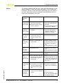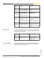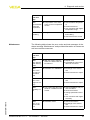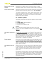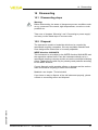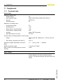
1
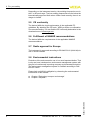
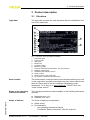
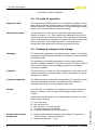
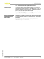
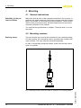
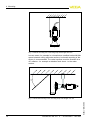
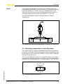
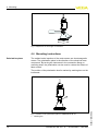
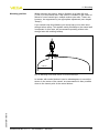
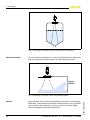
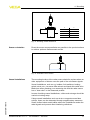
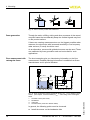
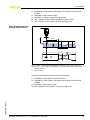
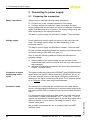
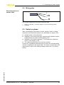
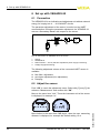
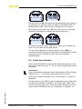
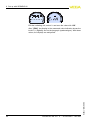
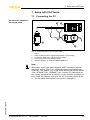
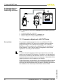
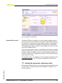
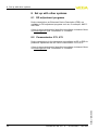
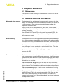
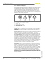
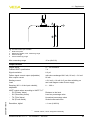
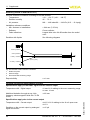
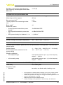
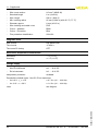
Operating Instructions VEGAPULS WL 61 4 … 20 mA/HART - two-wire Document ID: 38061 Radar Contents Contents 1 About this document 1.1 1.2 1.3 2 . . . . . . . . . . . . . . . . . . . . . . . . .. .. .. .. .. .. .. .. 5 5 5 5 6 6 6 6 . . . . . . . . . . . . . . . . . . . . . . . . . . . . . . . . . . . . . . . . .. .. .. .. 7 8 8 9 General instructions . . . . . . . . . . . . . . Mounting versions . . . . . . . . . . . . . . . Mounting preparations, mounting strap. Mounting instructions . . . . . . . . . . . . . . . . . . . . . . . . . . . . . . . . . . . . . . . . . . . . . . . . . .. .. .. .. 10 10 13 14 Preparing the connection . . . . . . . . . . . . . . . . . . . . . Wiring plan. . . . . . . . . . . . . . . . . . . . . . . . . . . . . . . . Switch on phase. . . . . . . . . . . . . . . . . . . . . . . . . . . . 20 21 21 Structure . . . . . . . . . . . . . . . . . . . . Principle of operation . . . . . . . . . . . Packaging, transport and storage . . Accessories and replacement parts . . . . . Connection. . . . . . . . . . . . . . . . . . . . . . . . . . . . . . . . Adjust the sensor . . . . . . . . . . . . . . . . . . . . . . . . . . . Scale the indication . . . . . . . . . . . . . . . . . . . . . . . . . 22 22 23 Connecting the PC . . . . . . . . . . . . . . . . . . . . . . . . . . Parameter adjustment with PACTware . . . . . . . . . . . . Saving the parameter adjustment data . . . . . . . . . . . . 25 26 27 28 28 Maintenance . . . . . . . . . . . . . . . . . . . . . . . . . . . . . . 29 VEGAPULS WL 61 • 4 … 20 mA/HART - two-wire 38061-EN-110616 DD adjustment programs . . . . . . . . . . . . . . . . . . . . . Communicator 375, 475 . . . . . . . . . . . . . . . . . . . . . . Diagnosis and service 9.1 2 . . . . . . . . Set up with other systems 8.1 8.2 9 . . . . . . . . Setup with PACTware 7.1 7.2 7.3 8 . . . . . . . . Set up with VEGADIS 62 6.1 6.2 6.3 7 . . . . . . . . Connecting to power supply 5.1 5.2 5.3 6 . . . . . . . . Mounting 4.1 4.2 4.3 4.4 5 Authorised personnel . . . . . . . . . . . . . . Appropriate use . . . . . . . . . . . . . . . . . . Warning about misuse . . . . . . . . . . . . . General safety instructions . . . . . . . . . . CE conformity . . . . . . . . . . . . . . . . . . . Fulfillment of NAMUR recommendations Radio approval for Europe . . . . . . . . . . Environmental instructions. . . . . . . . . . . Product description 3.1 3.2 3.3 3.4 4 4 4 4 For your safety 2.1 2.2 2.3 2.4 2.5 2.6 2.7 2.8 3 Function. . . . . . . . . . . . . . . . . . . . . . . . . . . . . . . . . . Target group . . . . . . . . . . . . . . . . . . . . . . . . . . . . . . Symbolism used. . . . . . . . . . . . . . . . . . . . . . . . . . . . Contents .. .. .. .. .. 29 30 34 35 36 10.1 Dismounting steps . . . . . . . . . . . . . . . . . . . . . . . . . . 10.2 Disposal . . . . . . . . . . . . . . . . . . . . . . . . . . . . . . . . . 37 37 9.2 9.3 9.4 9.5 9.6 Measured value and event memory . Status messages . . . . . . . . . . . . . . Fault rectification . . . . . . . . . . . . . . Software update . . . . . . . . . . . . . . . How to proceed in case of repair. . . . . . . . . . . . . . . . . . . . . . . . . . . . . . . . . . . . . . . . . . . . . . . . . . . . . . . . . . 10 Dismounting 11 Supplement 11.1 Technical data . . . . . . . . . . . . . . . . . . . . . . . . . . . . . 11.2 Dimensions . . . . . . . . . . . . . . . . . . . . . . . . . . . . . . . 38 44 38061-EN-110616 Safety instructions for Ex areas Please note the Ex-specific safety information for installation and operation in Ex areas. These safety instructions are part of the operating instructions manual and come with the Ex-approved instruments. Editing status: 2011-05-31 VEGAPULS WL 61 • 4 … 20 mA/HART - two-wire 3 1 About this document 1 About this document 1.1 Function This operating instructions manual provides all the information you need for mounting, connection and setup as well as important instructions for maintenance and fault rectification. Please read this information before putting the instrument into operation and keep this manual accessible in the immediate vicinity of the device. 1.2 Target group This operating instructions manual is directed to trained qualified personnel. The contents of this manual should be made available to these personnel and put into practice by them. 1.3 Symbolism used Information, tip, note This symbol indicates helpful additional information. Caution: If this warning is ignored, faults or malfunctions can result. Warning: If this warning is ignored, injury to persons and/or serious damage to the instrument can result. Danger: If this warning is ignored, serious injury to persons and/or destruction of the instrument can result. Ex applications This symbol indicates special instructions for Ex applications. l à 1 List The dot set in front indicates a list with no implied sequence. Action This arrow indicates a single action. Sequence Numbers set in front indicate successive steps in a procedure. 38061-EN-110616 4 VEGAPULS WL 61 • 4 … 20 mA/HART - two-wire 2 For your safety 2 For your safety 2.1 Authorised personnel All operations described in this operating instructions manual must be carried out only by trained specialist personnel authorised by the plant operator. During work on and with the device the required personal protective equipment must always be worn. 2.2 Appropriate use VEGAPULS WL 61 is a sensor for continuous level measurement. You can find detailed information on the application range in chapter "Product description". Operational reliability is ensured only if the instrument is properly used according to the specifications in the operating instructions manual as well as possible supplementary instructions. 2.3 Warning about misuse Inappropriate or incorrect use of the instrument can give rise to application-specific hazards, e.g. vessel overfill or damage to system components through incorrect mounting or adjustment. 2.4 General safety instructions This is a state-of-the-art instrument complying with all prevailing regulations and guidelines. The instrument must only be operated in a technically flawless and reliable condition. The operator is responsible for the trouble-free operation of the instrument. During the entire duration of use, the user is obliged to determine the compliance of the necessary occupational safety measures with the current valid rules and regulations and also take note of new regulations. The safety instructions in this operating instructions manual, the national installation standards as well as the valid safety regulations and accident prevention rules must be observed by the user. 38061-EN-110616 For safety and warranty reasons, any invasive work on the device beyond that described in the operating instructions manual may be carried out only by personnel authorised by the manufacturer. Arbitrary conversions or modifications are explicitly forbidden. The safety approval markings and safety tips on the device must also be observed. VEGAPULS WL 61 • 4 … 20 mA/HART - two-wire 5 2 For your safety Depending on the instrument version, the emitting frequencies are in the C or K band range. The low emitting frequencies are far below the internationally approved limit values. When used correctly, there is no danger to health. 2.5 CE conformity The device fulfills the legal requirements of the applicable EC guidelines. By attaching the CE mark, VEGA provides a confirmation of successful testing. You can find the CE conformity declaration in the download area of www.vega.com. 2.6 Fulfillment of NAMUR recommendations The device fulfills the requirements of the applicable NAMUR recommendations. 2.7 Radio approval for Europe The instrument is approved according to EN 302372-1/2 (2006-04) for use in closed vessels. 2.8 Environmental instructions Protection of the environment is one of our most important duties. That is why we have introduced an environment management system with the goal of continuously improving company environmental protection. The environment management system is certified according to DIN EN ISO 14001. Please help us fulfil this obligation by observing the environmental instructions in this manual: l l Chapter "Packaging, transport and storage" Chapter "Disposal" 38061-EN-110616 6 VEGAPULS WL 61 • 4 … 20 mA/HART - two-wire 3 Product description 3 Product description 3.1 Structure Type label The type label contains the most important data for identification and use of the instrument: 1 2 3 4 5 6 7 8 9 12 11 10 Fig. 1: Structure of the type label (example) 1 2 3 4 5 6 7 8 9 10 11 12 Serial number The serial number on the type label of the instrument allows you to call up the order data, operating instructions manuals, sensor data for the service DTM as well as the test certificate (depending on the instrument). To do this, go to www.vega.com, "VEGA Tools" and "serial number search". Scope of the operating instructions manual This operating instructions manual applies to the following instrument versions: l l Scope of delivery 38061-EN-110616 Instrument type Product code Approvals Electronics Protection rating Measuring range Process and ambient temperature, process pressure Material, wetted parts Hardware and software version Order number Serial number of the instrument ID numbers, instrument documentation Hardware from 1.0.0 Software from 4.4.0 The scope of delivery encompasses: l l Radar sensor Documentation - this operating instructions manual - Ex-specific "Safety instructions" (with Ex versions) VEGAPULS WL 61 • 4 … 20 mA/HART - two-wire 7 3 Product description - if necessary, further certificates 3.2 Principle of operation Application area The radar sensor VEGAPULS WL 61 is particularly suitable for use in pump stations and rain overflow basins, for flow measurement in open flumes as well as for gauge measurement. The high housing protection rating of the instrument allows outdoor mounting. Functional principle The antenna of the radar sensor emits short radar pulses with a duration of approx. 1 ns. These pulses are reflected by the product and received by the antenna as echoes. The running time of the radar pulses from emission to reception is proportional to the distance and hence to the level. The determined level is converted into an appropriate output signal and outputted as measured value. 3.3 Packaging, transport and storage Packaging The device was protected by packaging during transport. Its capacity to handle normal loads during transport is assured by a test according to DIN EN 24180. The packaging of standard instruments consists of environmentfriendly, recyclable cardboard. For special versions, PE foam or PE foil is also used. Dispose of the packaging material via specialised recycling companies. Transport Transport must be carried out under consideration of the notes on the transport packaging. Nonobservance of these instructions can cause damage to the device. Transport inspection The delivery must be checked for completeness and possible transit damage immediately at receipt. Ascertained transit damage or concealed defects must be appropriately dealt with. Storage Up to the time of installation, the packages must be left closed and stored according to the orientation and storage markings on the outside. Unless otherwise indicated, the packages must be stored only under the following conditions: Not in the open Dry and dust free Not exposed to corrosive media Protected against solar radiation Avoiding mechanical shock and vibration l Storage and transport temperature see chapter "Supplement Technical data - Ambient conditions" Relative humidity 20 … 85 % l 8 VEGAPULS WL 61 • 4 … 20 mA/HART - two-wire 38061-EN-110616 Storage and transport temperature l l l l l 3 Product description 3.4 Accessories and replacement parts Interface adapter The interface adapter VEGACONNECT enables the connection of communication-capable instruments to the USB interface of a PC. For parameter adjustment of these instruments, an adjustment software such as PACTware with VEGA-DTM is required. You can find further information in the operating instructions "Interface adapter VEGACONNECT" (Document-ID 32628). External indicating and adjustment unit with HART protocol VEGADIS 62 is suitable for measured value indication and adjustment of sensors with HART protocol. It is looped into the 4 … 20 mA/HART signal cable. 38061-EN-110616 You can find further information in the operating instructions "VEGADIS 62" (Document-ID 36469). VEGAPULS WL 61 • 4 … 20 mA/HART - two-wire 9 4 Mounting 4 Mounting 4.1 General instructions Suitability for the process conditions Make sure that all parts of the instrument exposed to the process, in particular the active measuring component, process seal and process fitting, are suitable for the existing process conditions. These include above all the process pressure, process temperature as well as the chemical properties of the medium. You can find the specifications in chapter "Technical data" or on the type label. 4.2 Mounting versions Straining clamp The most simple way to mount the instrument is via a straining clamp. For this purpose, the connection cable is provided with a strain relief rope of Kevlar. This rope must be anchored separately. In order to avoid faulty measured values, make sure that the sensor does not oscillate. Fig. 2: Mounting via the connection cable, for example, via a straining clamp 38061-EN-110616 10 VEGAPULS WL 61 • 4 … 20 mA/HART - two-wire 4 Mounting Mounting bracket For a rigid mounting, a mounting bracket with opening for thread G1½A, e.g. from the VEGA product range, is recommended. The mounting the sensor in the bracket is carried out via a G1½A counter nut of plastic. Take note of chapter 4.4 "Mounting instructions" for the distance to the wall. > 200 mm (7.87") Fig. 3: Mounting via a mounting bracket Mounting strap The optional mounting strap allows the sensor to be mounted on a bracket or a ceiling: l l Length 170 mm for wall mounting Length 300 mm for ceiling mounting 38061-EN-110616 As a standard feature, the mounting is carried out vertically. This ensures the swivelling of the sensor for optimum orientation. VEGAPULS WL 61 • 4 … 20 mA/HART - two-wire 11 4 Mounting Fig. 4: Vertical mounting via a mounting strap with length 300 mm 45° In some cases, for example in a closed storm overflow basin with little space between ceiling and water surface, horizontal mounting of the sensor is recommended. The radar impulses must be directed via a 45° reflector - for example a stainless steel sheet - to the water surface. > 50 mm (1.97") Fig. 5: Horizontal mounting via a mounting strap with length 170 mm 38061-EN-110616 12 VEGAPULS WL 61 • 4 … 20 mA/HART - two-wire 4 Mounting Flange For mounting the instrument on a socket or a manhole cover, an unassembled combination compression flange is optionally available for DN 80 (ASME 3" or JIS 80), also as a retrofitting part. As an alternative, the instrument can be already supplied with a tight, fixmounted adapter flange from DN 100 (ASME 4" or JIS 100). You can find drawings of these mounting options in chapter "Dimensions". Fig. 6: Mounting by means of an adapter flange, for example, on a manhole lid. 4.3 Mounting preparations, mounting strap The optional strap is supplied unassembled and must be screwed to the sensor before setup with three hexagon socket screws M5x10 and spring washers. Max. torque, see chapter "Technical data". Required tools: Allen wrench size 4. 38061-EN-110616 There are two different versions for screwing the strap to the sensor. Depending on the selected version, the sensor can be rotated infinitely variable in the strap through 180° or in three steps 0°, 90° and 180°. Fig. 7: Turning by fastening in the centre VEGAPULS WL 61 • 4 … 20 mA/HART - two-wire 13 4 Mounting Fig. 8: Adjustment of the angle of inclination 4.4 Mounting instructions Polarisation plane The emitted radar impulses of the radar sensor are electromagnetic waves. The polarisation plane is the direction of the electrical wave component. By turning the instrument in the connection flange or mounting strap, the polarisation can be used to reduce the effects of false echoes. The position of the polarisation level is marked by marking bars on the instrument. 1 1 14 Marking bar VEGAPULS WL 61 • 4 … 20 mA/HART - two-wire 38061-EN-110616 Fig. 9: Position of the polarisation plane of VEGAPULS WL 61 4 Mounting Mounting position When mounting the sensor, keep a distance of at least 200 mm (7.874 in) to the vessel wall. If the sensor is installed in the center of dished or round vessel tops, multiple echoes can arise. These can, however, be suppressed by an appropriate adjustment (see chapter "Setup"). If you cannot keep this distance you should carry out a false echo storage before setup. This applies mainly if buildup on the vessel wall is expected. In this case, we recommend repeating a false echo storage later with existing buildup. > 200 mm (7.87") Fig. 10: Mounting of the radar sensor on round vessel tops 38061-EN-110616 In vessels with conical bottom it can be advantageous to mount the sensor in the center of the vessel, as measurement is then possible down to the lowest point of the vessel bottom. VEGAPULS WL 61 • 4 … 20 mA/HART - two-wire 15 4 Mounting Fig. 11: Mounting of the radar sensor on vessels with conical bottom Inflowing medium Do not mount the instrument in or above the filling stream. Make sure that you detect the product surface, not the inflowing product. Fig. 12: Mounting of the radar sensor with inflowing medium 16 Approximate values of the socket heights are shown in the following illustration. The socket end should be smooth and burr-free, if possible also rounded. Aftr mounting, you have to carry out a false signal memory during the parameter adjustment. VEGAPULS WL 61 • 4 … 20 mA/HART - two-wire 38061-EN-110616 Socket 4 Mounting h d d h 80 mm / 3.15" 300 mm / 11.8" 100 mm / 4" 500 mm / 19.69" 125 mm / 5" 600 mm / 23.6" 150 mm / 6" 800 mm / 31.5" Fig. 13: Deviating socket dimensions Sensor orientation Direct the sensor as perpendicular as possible to the product surface to achieve optimum measurement results. Fig. 14: Orientation of the sensor Vessel installations The mounting location of the radar sensor should be a place where no other equipment or fixtures cross the path of the microwave signals. Vessel installations, such as e.g. ladders, limit switches, heating spirals, struts, etc., can cause false echoes and impair the useful echo. Make sure when planning your measuring site that the radar sensor has a "clear view" to the measured product. 38061-EN-110616 In case of existing vessel installations, a false echo storage should be carried out during setup. If large vessel installations such as struts or supports cause false echoes, these can be attenuated through supplementary measures. Small, inclined sheet metal baffles above the installations scatter the radar signals and prevent direct interfering reflections. VEGAPULS WL 61 • 4 … 20 mA/HART - two-wire 17 4 Mounting Fig. 15: Cover smooth profiles with deflectors Foam generation Through the action of filling, stirring and other processes in the vessel, compact foams that considerably damp the emitted signals may form on the product surface. If foams are causing measurement errors, the biggest possible radar antennas, the electronics with increased sensitivity or low frequency radar sensors (C band) should be used. As an alternative, sensors with guided microwave can be used. These are unaffected by foam generation and are best suited for such applications. The short examples give you introductory information on the flow measurement. Detailed planning information is available from flume manufacturers and in special literature. 1 3 ... 4 hmax dmin Flow measurement with rectangular flume 2 3 90° ≥ 2 mm x hmax ≥ 50 mm hmax 90° 4 Fig. 16: Flow measurement with rectangular flume: dmin. = min. distance of the sensor (see chapter "Technical data"); hmax. = max. filling of the rectangular flume Overflow orifice (side view) Headwater Tail water Overfall orifice (view from bottom water) In general, the following points must be observed: l 18 Install the sensor on the headwater side VEGAPULS WL 61 • 4 … 20 mA/HART - two-wire 38061-EN-110616 1 2 3 4 4 Mounting l l l l l Installation in the centre of the flume and vertical to the liquid surface Distance to the overfall orifice Distance of orifice opening above ground Min. distance of the orifice opening to bottom water Min. distance of the sensor to max. storage level Flow measurement with Khafagi Venturi flume 3 ... 4 x hmax d 90° hmax 2 1 B Fig. 17: Flow measurement with Khafagi-Venturi flume: d = Min. distance to sensor; hmax. = max. filling of the flume; B = tightest constriction in the flume 1 2 Position sensor Venturi flume In general, the following points must be observed: l l 38061-EN-110616 l l Installation of the sensor at the inlet side Installation in the centre of the flume and vertical to the liquid surface Distance to the Venturi flume Min. distance of the sensor to max. storage level VEGAPULS WL 61 • 4 … 20 mA/HART - two-wire 19 5 Connecting to power supply 5 Connecting to power supply 5.1 Preparing the connection Safety instructions Always keep in mind the following safety instructions: l l Connect only in the complete absence of line voltage If voltage surges are expected, install overvoltage arresters Supply voltage and current output are carried on separate connection cables if reliable separation is required. The supply voltage range can differ depending on the instrument version. The data for power supply are specified in chapter "Technical data". Voltage supply Power supply and current signal are carried on the same two-wire cable. The voltage supply range can differ depending on the instrument version. The data for power supply are specified in chapter "Technical data". Provide a reliable separation between the supply circuit and the mains circuits according to DIN VDE 0106 part 101. Keep in mind the following additional factors that influence the operating voltage: l l Output voltage of the power supply unit can be lower under nominal load (with a sensor current of 20.5 mA or 22 mA in case of fault message) Influence of additional instruments in the circuit (see load values in chapter "Technical data") Connection to signal conditioning instruments The signal conditioning instruments VEGAMET and VEGASCAN have digital sensor recognition. When connecting VEGAPULS WL 61, an up-to-date software version of the signal conditioning instrument is required for the signal conditioning instrument. For a software update go to "Software" under "www.vega.com/downloads". Connection cable The instrument is connected with standard two-wire cable without screen. If electromagnetic interference is expected which is above the test values of EN 61326 for industrial areas, screened cable should be used. We generally recommend the use of screened cable for HART multidrop mode. 20 VEGAPULS WL 61 • 4 … 20 mA/HART - two-wire 38061-EN-110616 For instruments with housing and cable gland, use cable with round cross-section. A cable outer diameter of 5 … 9 mm (0.2 … 0.35 in) ensures the seal effect of the cable gland. If you are using cable with a different diameter or cross-section, exchange the seal or use a suitable cable gland. 5 Connecting to power supply 5.2 Wiring plan Wire assignment connection cable + 1 2 Fig. 18: Wire assignment fix-connected connection cable 1 2 brown (+) and blue (-) to power supply or to the processing system Shielding 5.3 Switch on phase After connecting the instrument to power supply or after a voltage recurrence, the instrument carries out a self-check for approx. 30 s: l l l l Internal check of the electronics Indication of the instrument type, hardware and software version, measurement loop name on the display or PC Indication of the status message "F 105 Determine measured value" on the display or PC The output signal jumps to the set error current 38061-EN-110616 As soon as a plausible measured value is found, the corresponding current is outputted to the signal cable. The value corresponds to the actual level as well as the settings already carried out, e.g. factory setting. VEGAPULS WL 61 • 4 … 20 mA/HART - two-wire 21 6 Set up with VEGADIS 62 6 Set up with VEGADIS 62 6.1 Connection The VEGADIS 62 is an indicating and adjustment unit without external energy for looping into 4 … 20 mA/HART circuits. The parameter adjustment of the sensor is carried out via HART communication. During the parameter adjustment, the VEGADIS 62 acts as a Secondary Master with respect to the sensor. = ~ 2 3 4 1 Fig. 19: Connection of VEGADIS 62 to the sensor 1 2 3 4 Sensor VEGADIS 62 HART resistor > 150 Ω (with low impedance power supply necessary) Voltage supply/Processing The following adjustment volume of the connected HART sensor is available: l l l Min./Max. adjustment zero/span adjustment (live adjustment) Damping 6.2 Adjust the sensor Push "OK" to reach the adjustment menu. Select with [↑] and [↓] the submenu "Measurement" and confirm with "OK". Move to the menu item "Unit". There the instrument unit of the sensor is displayed, for example "m". 22 VEGAPULS WL 61 • 4 … 20 mA/HART - two-wire 38061-EN-110616 Move further to the menu item "MB begin", there the max. measuring distance is displayed, for example the default setting 15 m. 6 Set up with VEGADIS 62 Edit this value via "OK" and adjust the requested value via [↑] and [↓], for example 5 m. Save the value via "OK", the VEGAPULS WL 61 displays briefly "Wait", the the value is transferred to the sensor. Move further to the menu item "MB end", there the min. measuring distance is displayed, for example the default setting 0 m. Proceed in the same way for "MB end, by entering for example the value 12 m and save as described before. The min./max. adjustment is thereby finished. After "[ESC]" is pressed, the display shows in the measured value display the currently measured level in m (digital) and the level on the bargraph (quasianalogue). 6.3 Scale the indication First of all the VEGADIS 62 displays the measured distance in m as digital value and the level as 4 … 20 mA value quasianalogue on the bar graph. Information: Keep in mind that the displayed values are anticyclical. With increasing distance, the 4 … 20 mA value gets smaller and vice versa. Often not the measured distance in m, but the level in % should be displayed. 38061-EN-110616 For this purpose, push "OK" to reach the adjustment menu. Select with [↑] and [↓] the submenu "Indication" and confirm with "OK". Then move to the menu item "Unit". There the actual indicating unit of the sensor and the VEGAPULS WL 61 is displayed, for example, "m". VEGAPULS WL 61 • 4 … 20 mA/HART - two-wire 23 6 Set up with VEGADIS 62 Edit the indicating unit, select % and save the value with "OK". After "[ESC]" the display in the measured value indication shows the level in % (digitally) and on the bargraph (quasianalogue). With these values, the displays are anticyclical. 38061-EN-110616 24 VEGAPULS WL 61 • 4 … 20 mA/HART - two-wire 7 Setup with PACTware 7 Setup with PACTware 7.1 Connecting the PC Via interface adapter to the signal cable 4 N OPE 3 USB TWIST LO CK 2 1 5 Fig. 20: Connecting the PC to the signal cable 1 2 3 4 5 Sensor HART resistance 250 Ω (optional depending on processing) Connection cable with 2 mm pins and terminals Processing system/PLC/Voltage supply Interface adapter, for example VEGACONNECT 4 38061-EN-110616 Note: With power supply units with integrated HART resistance (internal resistance approx. 250 Ω), an additional external resistance is not necessary. This applies, e.g. to the VEGA instruments VEGATRENN 149A, VEGAMET 381, VEGAMET 391. Common Ex separators are also usually equipped with a sufficient current limitation resistance. In such cases, the interface converter can be connected parallel to the 4 … 20 mA cable (dashed line in the previous illustration). VEGAPULS WL 61 • 4 … 20 mA/HART - two-wire 25 7 Setup with PACTware Via interface adapter to the VEGAMET signal conditioning instrument 3 1 2 1 2 2 on % VEGAMET 381 OPE N CK LO 1 TWIST USB 4 Fig. 21: Connection of the PC to the VEGAMET signal conditioning instrument 1 2 3 4 Sensor Connection cable with 2 mm pins Signal conditioning instrument, e.g. VEGAMET 381 Interface adapter, for example VEGACONNECT 4 7.2 Parameter adjustment with PACTware Prerequisites For parameter adjustment of the sensor via a Windows PC, the configuration software PACTware and a suitable instrument driver (DTM) according to FDT standard are required. The up-to-date PACTware version as well as all available DTMs are compiled in a DTM Collection. The DTMs can also be integrated in other frame applications according to FDT standard. Note: To ensure that all instrument functions are supported, you should always use the latest DTM Collection. Furthermore, not all described functions are included in older firmware versions. You can download the latest instrument software from our homepage. A description of the update procedure is also available in the Internet. Further setup steps are described in the operating instructions manual "DTM Collection/PACTware" attached to each DTM Collection and which can also be downloaded from the Internet. Detailed descriptions are available in the online help of PACTware and the DTMs. 38061-EN-110616 26 VEGAPULS WL 61 • 4 … 20 mA/HART - two-wire 7 Setup with PACTware Fig. 22: Example of a DTM view Standard/Full version All device DTMs are available as a free-of-charge standard version and as a full version that must be purchased. In the standard version, all functions for complete setup are already included. An assistant for simple project configuration simplifies the adjustment considerably. Saving/printing the project as well as import/export functions are also part of the standard version. In the full version there is also an extended print function for complete project documentation as well as a save function for measured value and echo curves. In addition, there is a tank calculation program as well as a multiviewer for display and analysis of the saved measured value and echo curves. The standard version is available as a free-of-charge download under http://www.vega.com. The full version is available on CD from the agency serving you. 7.3 Saving the parameter adjustment data 38061-EN-110616 We recommend documenting or saving the parameter adjustment data via PACTware. That way the data are available for multiple use or service purposes. VEGAPULS WL 61 • 4 … 20 mA/HART - two-wire 27 8 Set up with other systems 8 Set up with other systems 8.1 DD adjustment programs Device descriptions as Enhanced Device Description (EDD) are available for DD adjustment programs such as, for example, AMS™ and PDM. A free-of-charge download of these files is available via Internet. Move via www.vega.com and "Downloads" to "Software". 8.2 Communicator 375, 475 Device descriptions for the instrument are available as DD or EDD for parameter adjustment with the Field Communicator 375 or 475. A free-of-charge download of these files is available via Internet. Move via www.vega.com and "Downloads" to "Software". 38061-EN-110616 28 VEGAPULS WL 61 • 4 … 20 mA/HART - two-wire 9 Diagnosis and service 9 Diagnosis and service 9.1 Maintenance If the device is used correctly, no maintenance is required in normal operation. 9.2 Measured value and event memory Measured value memory The instrument has an integrated measured value memory with time stamp. Up to 100,000 measured values can be saved in the sensor in a ringing memory. Each entry contains date/time as well as the respective measured value. Stored values are for exmaple sensor value, level, current value, reliability and electronics temperature. The data remain even in case of voltage interruption. Via a PC with PACTware/DTM or the control system with EDD, the requested values and recording conditions are stipulated. Data are also read our or reset. Event memory The instrument also has an integrated event memory with time stamp. Up to 500 events are automatically stored in the sensor and are delete protected. Each entry contains date/time, event time, event description and value. Event types are, for example, parameter modifications, status and error messages as well as switch on and switch off times. The data remain also in case of voltage interruption. The data are read out via a PC with PACTware/DTM or the control system with EDD. Echo curve memory The instrument also has an integrated echo curve memory in which echo curves can be stored for diagnostic purposes. The echo curves are stored with date and time as well as the corresponding echo data. The data remain even in case of voltage interruption. The memory is divided into two sections: Echo curve of the setup: here you can store the echo curve as a reference during setup. This echo curve can be used, for example, to detect changes of the installation conditions or buildup on the antenna. 38061-EN-110616 Echo curve memory: up to 10 echo curves can be stored in a ring buffer in this memory section. The requested values and recording conditions are defined via a PC with PACTware/DTM or the control system with EDD. Data are also read out or reset. Depending on the instrument, the echo curve created during setup can be stored alternatively also via the indicating and adjustment module. VEGAPULS WL 61 • 4 … 20 mA/HART - two-wire 29 9 Diagnosis and service 9.3 Status messages The instrument has self-monitoring and diagnosis according to NE 107 and VDI/VDE 2650. Status messages regarding device status are outputted. Detailed messages are displayed during diagnosis via DTM, indicating and adjustment module (dependent on the sensor type) and EDD; there also in the respective colour. The messages are divided into the following categories: 1 2 3 4 Fig. 23: Pictograms of the status messages 1 2 3 4 Failure - red Function check - orange Out of specification - yellow Maintenance - blue Failure: Due to a malfunction in the instrument, a failure message is outputted. This status message is always activated and cannot be deactivated. Function check: The instrument is in operation, the measured value is temporarily invalid (for example during simulation). This status message is always activated and cannot be deactivated by the user. Out of specification: The measured value is unstable because the instrument specification is exceeded (e.g. electronics temperature). This status message is always inactive and can be activated via DTM and EDD. The error codes and text messages are dispayed via the indicating and adjustment module as well as DTM and EDD in the control system. Additional information on error statstics is displayed in the menu Diagnosis under "Device status" in the indicating and adjustment module as well as in the DTM and EDD. 30 VEGAPULS WL 61 • 4 … 20 mA/HART - two-wire 38061-EN-110616 Maintenance: Due to external influences, the instrument function is limited. The measurement is affected but the measured value is still valid. Plan instrument for maintenance because failure must be expected in the near future (for example due to buildup). This status message is always inactive and can be activated via DTM and EDD. The error codes are dispayed via the indicating and adjustment module as well as DTM and EDD in the control system. Additional information on error statstics is displayed in the menu Diagnosis under "Device status" in the indicating and adjustment module as well as in the DTM and EDD. 9 Diagnosis and service Failure The following table shows the error codes and text messages in the status message "Failure" and gives information on the reason and rectification. Keep in mind that some specification are only valid for four-wire instruments and the electronics with VEGAPULS WL 61 cannot be exchanged by the user. Code Text message Cause F013 no measured value available l Sensor does not detect an l Check or correct installaecho during operation tion and/or parameter adjustment l Antenna system contamil Clean or exchange process nated or defective component or antenna Removal 38061-EN-110616 F017 l Adjustment not within spe- l Change adjustment accorcification ding to the limit values Adjustment (difference between min. span too small and max. ≥ 10 mm) F025 Error in the linearization table l Index markers are not continuously rising, for examle unlogical value pairs l Check linearization table l Delete table/Create new F036 No operable software l Failed or interrupted software update l Repeat software update l Check electronics version l Exchange of the electronics l Send instrument for repair F040 Error in the electronics l Hardware defect l Exchange of the electronics l Send instrument for repair F080 l General software error l Separate operating voltage briefly F105 Determine measured value l The instrument is still in the l Wait for the warm-up phase start phase, the measured l Duration depending on the value could not yet be version and parameter addetermined justment up to approximately 3 min. F113 Communication error l EMC interferences l Remove EMC influences l Transmission error with the l Exchange 4-wire power external communication supply unit or electronics with 4-wire power supply unit F125 l Temperature of the electronics in the non-specified Unpermissible section electronics temperature VEGAPULS WL 61 • 4 … 20 mA/HART - two-wire l Check ambient temperature l Isolate electronics l Use instrument with higher temperature range 31 9 Diagnosis and service Function check Out of specification Code Text message Cause Removal F260 Error in the calibration l Error in the calibration car- l Exchange of the electroried out in the factory nics l Error in the EEPROM l Send instrument for repair F261 Error in the configuration l Error during setup l False signal suppression faulty l Error when carrying out a reset l Repeat setup l Repeat reset F264 Installation/Setup error l Adjustment not within the vessel height/measuring range l Max. measuring range of the instrument not sufficient l Check or correct installation and/or parameter adjustment l Use an instrument with bigger measuring range F265 Measurement function disturbed l Sensor does no longer carry out a measurement l Operating voltage too low l Check operating voltage l Carry out a reset l Separate operating voltage briefly The following table shows the error codes and text messages in the status message "Function check" and provides information on causes as well as corrective measures. Code Text message Cause Removal C700 Simulation l Simulation active l Finish simulation l Wait for the automatic end after 60 mins. The following table shows the error codes and text messages in the status message "Out of specification" and provides information on causes as well as corrective measures. 38061-EN-110616 32 VEGAPULS WL 61 • 4 … 20 mA/HART - two-wire 9 Diagnosis and service Code Text message Cause S600 l Temperature of the electronics in the non-specified Unpermissible section electronics temperature S601 Overfilling 38061-EN-110616 Maintenance Removal l Check ambient temperature l Isolate electronics l Use instrument with higher temperature range l Danger of vessel overfilling l Make sure that there is no further filling l Check level in the vessel The following table shows the error codes and text messages in the status message "Maintenance" and provides information on causes as well as corrective measures. Code Text message Cause Removal M500 Error with the reset delivery status l With the reset to delivery status, the data could not be restored l Repeat reset l Load XML file with sensor data into the sensor M501 Error in the non-active linearization table l Hardware error EEPROM l Exchange of the electronics l Send instrument for repair M502 Error in the diagnosis memory l Hardware error EEPROM l Exchange of the electronics l Send instrument for repair M503 Reliability too low l The echot/noise ratio is the l Check installation and prosmall for a reliable measucess conditions rement l Clean the antenna l Change polarisation direction l Use instrument with higher sensitivity M504 Error on an device interface l Hardware defect VEGAPULS WL 61 • 4 … 20 mA/HART - two-wire l Check connections l Exchange of the electronics l Send instrument for repair 33 9 Diagnosis and service Code Text message Cause Removal M505 No echo available l Level echo can no longer be detected l Clean the antenna l Use a more suitable antenna/sensor l Remove possible false echoes l Optimize sensor position and orientation 9.4 Fault rectification Reaction when malfunctions occur The operator of the system is responsible for taking suitable measures to rectify faults. Fault rectification The first measures to be taken are to check the output signal as well as to evaluate the error messages via the indicating and adjustment module. Further comprehensive diagnostics can be carried out on a PC with the software PACTware and the suitable DTM. In many cases, the causes can be determined this way and faults rectified. Checking the 4 … 20 mA signal Connect a handmultimeter in the suitable measuring range according to the wiring plan. The following table describes possible errors in the current signal and helps to remove them: Error Cause Removal 4 … 20 mA signal Level fluctuations Set damping according to the instrunot stable ment via the indicating and adjustment module or PACTware/DTM 4 … 20 mA signal Electrical conmissing nection faulty Voltage supply missing Check connection according to chapter "Connection steps" and if necessary, correct according to chapter "Wiring plan" Check cables for breaks; repair if necessary Operating voltage Check, adapt if necessary too low or load resistance too high 34 VEGAPULS WL 61 • 4 … 20 mA/HART - two-wire 38061-EN-110616 Current signal Electronics moExchange the instrument or send it in greater than 22 mA dule in the sensor for repair or less than defective 3.6 mA 9 Diagnosis and service Reaction after fault rectification Depending on the failure reason and measures taken, the steps described in chapter "Set up" must be carried out again, if necessary. 24 hour service hotline Should these measures not be successful, please call in urgent cases the VEGA service hotline under the phone no. +49 1805 858550. The hotline is available to you 7 days a week round-the-clock. Since we offer this service world-wide, the support is only available in the English language. The service is free of charge, only the standard telephone costs will be charged. 9.5 Software update The following components are required to update the sensor software: l l l l l Sensor Voltage supply Interface adapter VEGACONNECT 4 PC with PACTware Current sensor software as file 38061-EN-110616 Caution: Keep in mind that a software update can lead to expiry of the approvals. You can find detailed information on our homepage www. vega.com. Load sensor software to PC At "www.vega.com/downloads" go to "Software". Select under "plics sensors and instruments", "Firmware updates" the respective instrument series and software version. Load the zip file via the right mouse key with "Save target as" e.g. on the desktop of your PC. Move with the right mouse key to the folder and select "Extract all". Save the extracted files, for example on the desktop. Prepare update Connect the sensor to power supply and provide a connection from the PC to the instrument via the interface adapter. Start PACTware and move via the menu "Project" to the VEGA project assistant. Select "USB" and "Set instruments online". Activate the project assistant with "Start". It automatically sets up the connection to the sensor and then signals "Search complete". Load software into sensor Select the sensor in the project and move in the PACTware menu bar to "Instrument data". The select "Additional functions" and "Software update". PACTware now checks the actual hardware and software version of the sensor and displays the data. This process takes approx. 60 s. Push the button "Update software" and select the previously extracted XML file. Then the software update can be started. The additional files are installed automatically. Depending on the sensor, this procedure lasts up to 1 hour. Then the message appears ""Software update successfully executed". VEGAPULS WL 61 • 4 … 20 mA/HART - two-wire 35 9 Diagnosis and service 9.6 How to proceed in case of repair If a repair is necessary, please proceed as follows: You can download a return form (23 KB) from our homepage at www. vega.com under: "Downloads - Forms and certificates - Repair form". By doing this you help us carry out the repair quickly and without having to call back for needed information. l l l l Print and fill out one form per instrument Clean the instrument and pack it damage-proof Attach the completed form and, if need be, also a safety data sheet outside on the packaging Please ask the agency serving you for the address of your return shipment. You can find the competent agency on our website www.vega.com. 38061-EN-110616 36 VEGAPULS WL 61 • 4 … 20 mA/HART - two-wire 10 Dismounting 10 Dismounting 10.1 Dismounting steps Warning: Before dismounting, be aware of dangerous process conditions such as e.g. pressure in the vessel, high temperatures, corrosive or toxic products etc. Take note of chapters "Mounting" and "Connecting to power supply" and carry out the listed steps in reverse order. 10.2 Disposal The instrument consists of materials which can be recycled by specialised recycling companies. We use recyclable materials and have designed the electronics to be easily separable. WEEE directive 2002/96/EG This instrument is not subject to the WEEE directive 2002/96/EG and the respective national laws. Pass the instrument directly on to a specialised recycling company and do not use the municipal collecting points. These may be used only for privately used products according to the WEEE directive. Correct disposal avoids negative effects on humans and the environment and ensures recycling of useful raw materials. Materials: see chapter "Technical data" 38061-EN-110616 If you have no way to dispose of the old instrument properly, please contact us concerning return and disposal. VEGAPULS WL 61 • 4 … 20 mA/HART - two-wire 37 11 Supplement 11 Supplement 11.1 Technical data General data Materials, wetted parts - Adapter flange PP - Seal, adapter flange FKM (COG VI500), EPDM (COG AP310) - Antenna PBT-GF 30 - Focussing lense PP Materials, non-wetted parts - Compression flange PP - Mounting strap 316L - Fixing screws, mounting strap 316L - Fixing screws, adapter flange 304 - Housing plastic PBT (Polyester) - type label support on cable PE hard Process fitting, mounting thread on the housing - Flange DIN from DN 80, ANSI from 3", JIS from DN 100 10K - Pipe thread, cylindrical (ISO 228 T1) G1½ A Instrument weight, depending on process fitting 0.7 … 3.4 kg (1.543 … 7.496 lbs) Weight suspension cable 0.1 kg/m (0.07 lbs/ft) Max. torque for mounting strap on sensor housing 4 Nm Input variable The measured variable is the distance between the process fitting of the sensor and the product surface. The reference plane is the lower side of the flange. 38 VEGAPULS WL 61 • 4 … 20 mA/HART - two-wire 38061-EN-110616 Measured variable 11 Supplement 3 4 1 2 Fig. 24: Data of the input variable 1 2 3 4 Reference plane Measured variable, max. measuring range Antenna length Useful measuring range 15 m (49.21 ft) Max. measuring range Output variable Output signal 4 … 20 mA/HART Fulfilled HART specification 7.0 Signal resolution 0.3 µA Failure signal current output (adjustable) mA-value unchanged 20.5 mA, 22 mA, < 3.6 mA Max. output current 22 mA Starting current ≤ 3.6 mA; ≤ 10 mA for 5 ms after switching on Load see load diagram under Power supply Damping (63 % of the input variable), adjustable 0 … 999 s 38061-EN-110616 HART output values according to HART 7.01) - PV (Primary Value) Distance to the level - SV (Secondary Value) Level as percentage value - TV (Third Value) Linearised percentage value - QV (Fourth Value) Scaled measured value < 1 mm (0.039 in) Resolution, digital 1) Default values, can be assigned individually VEGAPULS WL 61 • 4 … 20 mA/HART - two-wire 39 11 Supplement Accuracy (similar to DIN EN 60770-1) Process reference conditions according to DIN EN 61298-1 - Temperature +18 … +30 °C (+64 … +86 °F) - Relative humidity 45 … 75 % - Air pressure 860 … 1060 mbar/86 … 106 kPa (12.5 … 15.4 psig) Installation reference conditions - Min. distance to installations > 200 mm (7.874 in) - Reflector Corner reflector - False reflections Largest false echo 20 dB smaller than the useful echo Deviation with liquids See following diagrams 10 mm (0.394 in) 2 mm (0.079 in) 0 - 2 mm (- 0.079 in) 0,5 m (1.6 ft) - 10 mm (- 0.394 in) 3 1 2 Fig. 25: Deviation under reference conditions 1 2 3 Reference plane Antenna edge Recommended measuring range Reproducibility ≤ ±1 mm Variables influencing measurement accuracy Specifications apply to the HART signal and the current output Temperature drift - Digital output ±3 mm/10 K relating to the max. measuring range or max. 10 mm Additional deviation through strong, high frequency electromagnetic fields acc. to EN 61326 <±50 mm Specifications apply also to the current output ±0.03 %/10 K relating to the 16 mA span max. ±0.3 % Deviation on the current output by analogue/ digital conversion <±15 µA 40 VEGAPULS WL 61 • 4 … 20 mA/HART - two-wire 38061-EN-110616 Temperature drift - Current output 11 Supplement Deviation on the current output by strong, high frequency electromagnetic fields within EN 61326 <±150 µA Characteristics and performance data Frequency K-band (26 GHz technology) Measuring cycle time approx. 450 ms Step response time2) ≤3s Tracking speed of the measuring window max. 1 m/min Beam angle3) 10° Emitted HF power4) - Average spectral transmission power density -34 dBm/MHz EIRP - Max. spectral transmission power density +6 dBm/50 MHz EIRP - Max. power density in a distance of 1 m < 1 µW/cm² Ambient conditions Ambient, storage and transport temperature -40 … +80 °C (-40 … +176 °F) Process conditions For the process conditions, please also note the specifications on the type label. The lower value always applies. Vessel pressure -1 … 2 bar (-100 … 200 kPa/-14.5 … 29.0 psig) Process temperature (measured on the process fitting) -40 … +80 °C (-40 … +176 °F) Vibration resistance5) - With adapter flange - mechanical vibrations up to 2 g in the frequency range 5 … 200 Hz mechanical vibrations up to 1 g in the frequency range 5 … 200 Hz with mounting strap 38061-EN-110616 Electromechanical data - version IP 66/IP 68 (2 bar) Cable entry IP 68 cable gland Connection cable - Structure two wires, one Kevlar cable, braiding, cover 2) 3) 4) 5) Time span after a sudden distance change of max. 0.5 m until the output signal reaches for the first time 90% of the final value (IEC 61298-2). Outside the specified beam angle, the energy of the radar signal has a level which is reduced by 50 % (-3 dB) EIRP: Equivalent Isotropic Radiated Power Tested according to the guidelines of German Lloyd, GL directive 2. VEGAPULS WL 61 • 4 … 20 mA/HART - two-wire 41 11 Supplement - Wire cross-section 0.5 mm² (AWG 20) - Standard length 6 m (19.69 ft) - Max. length 550 m (1804 ft) - Min. bending radius 25 mm (0.984 in) with 25 °C (77 °F) - Diameter approx. 8 mm (0.315 in) - Wire isolating and cable cover PUR - Colour - standard Black - Colour - Ex-version Blue - Fire protection classification UL94-V0 Integrated clock Date format Day.Month.Year Time format 12 h/24 h Time zone Ex factory CET Electronics temperature measurement Resolution 1 °C (1.8 °F) Accuracy ±1 °C (1.8 °F) Voltage supply Operating voltage - Non-Ex instrument - Ex-ia instrument Interpolation protection 9.6 … 36 V DC 9.6 … 30 V DC Available Permissible residual ripple - Non-Ex, Ex-ia instrument ≤ 0.7 Veff (16 … 400 Hz) - for 9.6 V< UN < 14 V - for 18 V< UN < 36 V ≤ 1.0 Veff (16 … 400 Hz) see diagram 42 VEGAPULS WL 61 • 4 … 20 mA/HART - two-wire 38061-EN-110616 Load 11 Supplement Ω 1200 927 750 3 500 2 1 250 4 9,6 12 14 15,1 16 18 20 22 24 26 28 30 32 34 36 V Fig. 26: Voltage diagram 1 2 3 4 HART load Voltage limit Ex-ia instrument Voltage limit non-Ex/Ex-d instrument Operating voltage Electrical protective measures Protection rating IP 66/IP 68 (2 bar) Overvoltage category III Protection class II Approvals Instruments with approvals can have different technical data depending on the version. 38061-EN-110616 That's why the associated approval documents have to be noted with these instruments. They are part of the delivery or can be downloaded under www.vega.com via "VEGA Tools" and "serial number search" as well as via "Downloads" and "Approvals". VEGAPULS WL 61 • 4 … 20 mA/HART - two-wire 43 11 Supplement 11.2 Dimensions The following dimensional drawings represent only an extract of the possible versions. Detailed dimensional drawings can be downloaded on www.vega.com under "Downloads" and "Drawings". 38061-EN-110616 44 VEGAPULS WL 61 • 4 … 20 mA/HART - two-wire 11 Supplement VEGAPULS WL 61 - version with mounting strap 2,5 mm (0.10") 125 mm (4.92") 75 mm (2.95") 107 mm (4.21") 9 mm (0.35") 115 mm (4.53") 9 mm (0.35") 38061-EN-110616 85 mm (3.35") 12 mm (0.47") PP 15 mm (0.59") 8,5 mm (0.34") 19 mm (0.75") PBT-GF30 98 mm (3.86") 300 mm (11.81") 1.4301 12 mm (0.47") Fig. 27: VEGAPULS WL 61 - version with mounting bracket 170 or 300 mm in length VEGAPULS WL 61 • 4 … 20 mA/HART - two-wire 45 11 Supplement 19 mm (0.75") 126 mm (4.96") 10,5 mm (0.41") VEGAPULS WL 61 - version with compression flange ø 107 mm (4.21") ø 21 mm (0.83") ø 75 mm (2.95") ø 115 mm (4.53") ø 156 mm (6.14") ø 200 mm (7.87") Fig. 28: VEGAPULS WL 61 - compression flange DN 80/3"/JIS80 38061-EN-110616 46 VEGAPULS WL 61 • 4 … 20 mA/HART - two-wire 11 Supplement VEGAPULS WL 61 - version with adapter flange øD øk ød DN100 PN16 220 180 18 8x45°(=360°) DN150 PN16 285 240 8x45°(=360°) ASME 4" 150psi 228,6 190,5 22 19,1 ASME 6" 150psi 279,4 241,3 22,4 8x45°(=360°) JIS DN100 10K 210 175 19 8x45°(=360°) JIS DN150 10K 280 240 23 8x45°(=360°) øD øk ød DN100 PN16 8.66" 7.09" 0.71" 8x45°(=360°) DN150 PN16 11.22" 9.45" 0.87" 8x45°(=360°) ASME 4" 150psi 9.00" 7.50" 0.75" 8x45°(=360°) ASME 6" 150psi 11.00" 9.50" 0.88" 8x45°(=360°) JIS DN100 10K 8.27" 6.89" 0.75" 8x45°(=360°) JIS DN150 10K 11.02" 9.45" 0.91" 8x45°(=360°) mm ø 107 mm (4.21") 1 15 mm (0.59") ø 143 mm (5.63") ød ø 75 mm (2.95") ø 98 mm (3.86") ø 115 mm (4.53") 8 mm (0.32") 20 mm (0.79") 138 mm (5.43") 31 mm (1.22") inch 8x45°(=360°) 2 ø 126 mm (4.96") k D Fig. 29: VEGAPULS WL 61 - adapter flange DN 100/4"/JIS 100 as well as DN 150/6"/JIS 150 Adapter flange Seal 38061-EN-110616 1 2 VEGAPULS WL 61 • 4 … 20 mA/HART - two-wire 47 11 Supplement 11.3 Industrial property rights VEGA product lines are global protected by industrial property rights. Further information seehttp://www.vega.com. Only in U.S.A.: Further information see patent label at the sensor housing. VEGA Produktfamilien sind weltweit geschützt durch gewerbliche Schutzrechte. Nähere Informationen unterhttp://www.vega.com. Les lignes de produits VEGA sont globalement protégées par des droits de propriété intellectuelle. Pour plus d'informations, on pourra se référer au sitehttp://www.vega.com. VEGA lineas de productos están protegidas por los derechos en el campo de la propiedad industrial. Para mayor información revise la pagina webhttp://www.vega.com. Линии продукции фирмы ВЕГА защищаются по всему миру правами на интеллектуальную собственность. Дальнейшую информацию смотрите на сайтеhttp://www.vega.com. VEGA系列产品在全球享有知识产权保护。 进一步信息请参见网站<http://www.vega.com>。 11.4 Trademark All the brands as well as trade and company names used are property of their lawful proprietor/originator. 38061-EN-110616 48 VEGAPULS WL 61 • 4 … 20 mA/HART - two-wire Index INDEX A P Accessory - External indicating and adjustment unit 9 - Interface adapter 9 Application area 8 Packaging 8 Polarisation plane 14 R Repair 36 C Check signal 34 Connection cable 20 D DD (Device Description) 28 S Sensor orientation 17 Serial number 7 Service hotline 35 Status messages 30 Storage 8 E T Echo curve memory 29 EDD (Enhanced Device Description) 28 Error messages 30 Event memory 29 V F Vessel installations 17 Voltage supply 20 Type label 7 Fault rectification 34 Flow measurement - Khafagi-Venturi ume 19 - Rectangular ume 18 Foam generation 18 Functional principle 8 H HART resistor 25 I Inflowing medium 16 M Measured value memory 29 Mounting - Bracket 11 - Flange 13 - Straining clamp 10 - Strap 11 Mounting position 15 38061-EN-110616 N NAMUR NE 107 - Failure 31 - Function check 32 - Maintenance 33 - Out of specication 32 VEGAPULS WL 61 • 4 … 20 mA/HART - two-wire 49 Index 38061-EN-110616 50 VEGAPULS WL 61 • 4 … 20 mA/HART - two-wire 38061-EN-110616 Index VEGAPULS WL 61 • 4 … 20 mA/HART - two-wire 51 Printing date: VEGA Grieshaber KG Am Hohenstein 113 77761 Schiltach Germany Phone +49 7836 50-0 Fax +49 7836 50-201 E-mail: [email protected] www.vega.com ISO 9001 All statements concerning scope of delivery, application, practical use and operating conditions of the sensors and processing systems correspond to the information available at the time of printing. © VEGA Grieshaber KG, Schiltach/Germany 2011 Subject to change without prior notice 38061-EN-110616