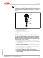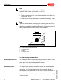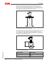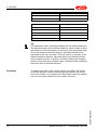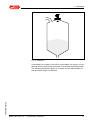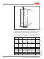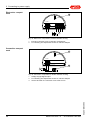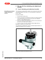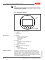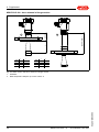
1
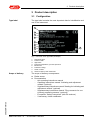
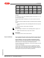
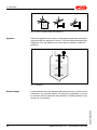
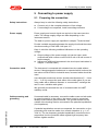
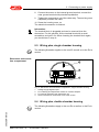
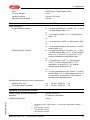
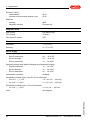
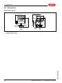
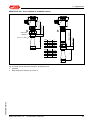
MBA PULS 400
4 … 20 mA/HART two-wire
Document ID:
36823
Contents
Contents
1
About this document
1.1
1.2
1.3
2
.
.
.
.
.
.
.
.
.
.
.
.
.
.
.
.
.
.
.
.
.
.
.
.
.
.
.
.
.
.
.
.
..
..
..
..
..
..
..
..
5
5
5
5
6
6
6
6
.
.
.
.
.
.
.
.
.
.
.
.
.
.
.
.
.
.
.
.
.
.
.
.
.
.
.
.
.
.
.
.
..
..
..
..
7
8
8
9
General instructions . . . . . . . . . . . . . . . . .
Mounting preparations - Horn antenna . . . .
Mounting preparations - Parabolic antenna.
Mounting instructions . . . . . . . . . . . . . . . .
.
.
.
.
.
.
.
.
.
.
.
.
.
.
.
.
.
.
.
.
.
.
.
.
..
..
..
..
10
10
11
12
.
.
.
.
.
.
.
.
.
.
.
.
.
.
.
.
.
.
.
.
.
.
.
.
.
.
.
.
.
.
.
.
.
.
.
.
..
..
..
..
..
..
25
26
27
27
29
29
Configuration . . . . . . . . . . . . . . . . .
Principle of operation . . . . . . . . . . .
Packaging, transport and storage . .
Accessories and replacement parts .
.
.
.
.
.
.
.
.
.
.
.
.
Preparing the connection . . . . . . . . . . . . .
Connection. . . . . . . . . . . . . . . . . . . . . . . .
Wiring plan, single chamber housing . . . . .
Wiring plan, double chamber housing . . . .
Wiring plan double chamber housing Ex d .
Switch on phase. . . . . . . . . . . . . . . . . . . .
Insert indicating and adjustment module.
Adjustment system . . . . . . . . . . . . . . . .
Parameter adjustment. . . . . . . . . . . . . .
Saving the parameter adjustment data . .
.
.
.
.
.
.
.
.
.
.
.
.
.
.
.
.
.
.
.
.
.
.
.
.
.
.
.
.
.
.
.
.
..
..
..
..
31
32
33
41
.
.
.
.
.
.
.
.
.
.
.
.
.
.
.
.
.
.
.
.
.
.
.
.
.
.
.
.
.
.
.
.
..
..
..
..
42
42
44
44
Diagnosis, fault rectification and service
Maintenance . . . . . . . . . . . . . . . . . .
Error messages according to NE 107
Rectify malfunctions . . . . . . . . . . . . .
How to proceed in case of repair. . . .
.
.
.
.
.
.
.
.
MBA PULS 400 • 4 … 20 mA/HART two-wire
36823-EN-091125
7.1
7.2
7.3
7.4
2
.
.
.
.
.
.
.
.
Set up with the indicating and adjustment module
6.1
6.2
6.3
6.4
7
.
.
.
.
.
.
.
.
Connecting to power supply
5.1
5.2
5.3
5.4
5.5
5.6
6
.
.
.
.
.
.
.
.
Mounting
4.1
4.2
4.3
4.4
5
.
.
.
.
.
.
.
.
Authorised personnel . . . . . . . . . . . . . .
Appropriate use . . . . . . . . . . . . . . . . . .
Warning about misuse . . . . . . . . . . . . .
General safety instructions . . . . . . . . . .
CE conformity . . . . . . . . . . . . . . . . . . .
Fulfillment of NAMUR recommendations
Radio approval for Europe . . . . . . . . . .
Radio approval for USA/Canada . . . . . .
Product description
3.1
3.2
3.3
3.4
4
4
4
4
For your safety
2.1
2.2
2.3
2.4
2.5
2.6
2.7
2.8
3
Function. . . . . . . . . . . . . . . . . . . . . . . . . . . . . . . . . .
Target group . . . . . . . . . . . . . . . . . . . . . . . . . . . . . .
Symbolism used. . . . . . . . . . . . . . . . . . . . . . . . . . . .
Contents
8
Dismounting
8.1
8.2
9
Dismounting steps . . . . . . . . . . . . . . . . . . . . . . . . . .
Disposal . . . . . . . . . . . . . . . . . . . . . . . . . . . . . . . . .
45
45
Supplement
9.1
9.2
Technical data . . . . . . . . . . . . . . . . . . . . . . . . . . . . .
Dimensions . . . . . . . . . . . . . . . . . . . . . . . . . . . . . . .
46
54
36823-EN-091125
Safety instructions for Ex areas
Please note the Ex-specific safety information for installation and
operation in Ex areas. These safety instructions are part of the
operating instructions manual and come with the Ex-approved
instruments.
MBA PULS 400 • 4 … 20 mA/HART two-wire
3
1 About this document
1 About this document
1.1 Function
This operating instructions manual provides all the information you
need for mounting, connection and setup as well as important
instructions for maintenance and fault rectification. Please read this
information before putting the instrument into operation and keep this
manual accessible in the immediate vicinity of the device.
1.2 Target group
This operating instructions manual is directed to trained qualified
personnel. The contents of this manual should be made available to
these personnel and put into practice by them.
1.3 Symbolism used
Information, tip, note
This symbol indicates helpful additional information.
Caution: If this warning is ignored, faults or malfunctions can
result.
Warning: If this warning is ignored, injury to persons and/or serious
damage to the instrument can result.
Danger: If this warning is ignored, serious injury to persons and/or
destruction of the instrument can result.
Ex applications
This symbol indicates special instructions for Ex applications.
l
à
1
List
The dot set in front indicates a list with no implied sequence.
Action
This arrow indicates a single action.
Sequence
Numbers set in front indicate successive steps in a procedure.
36823-EN-091125
4
MBA PULS 400 • 4 … 20 mA/HART two-wire
2 For your safety
2 For your safety
2.1 Authorised personnel
All operations described in this operating instructions manual must be
carried out only by trained specialist personnel authorised by the plant
operator.
During work on and with the device the required personal protective
equipment must always be worn.
2.2 Appropriate use
MBA PULS 400 is a sensor for continuous level measurement.
You can find detailed information on the application range in chapter
"Product description".
Operational reliability is ensured only if the instrument is properly used
according to the specifications in the operating instructions manual as
well as possible supplementary instructions.
2.3 Warning about misuse
Inappropriate or incorrect use of the instrument can give rise to
application-specific hazards, e.g. vessel overfill or damage to system
components through incorrect mounting or adjustment.
2.4 General safety instructions
This is a state-of-the-art instrument that fulfils the prevailing regulations
and guidelines. The instrument must only be operated in a technically
flawless and reliable condition. The operator is responsible for the
trouble-free operation of the instrument.
During the entire duration of use, the user is obliged to determine the
compliance of the required occupational safety measures with the
current valid rules and regulations and also take note of new
regulations.
The safety instructions in this operating instructions manual, the
national installation standards as well as the valid safety regulations
and accident prevention rules must be observed by the user.
36823-EN-091125
For safety and warranty reasons, any invasive work on the device
beyond that described in the operating instructions manual may be
carried out only by personnel authorised by the manufacturer. Arbitrary
conversions or modifications are explicitly forbidden.
The safety approval markings and safety tips on the device must be
also observed.
MBA PULS 400 • 4 … 20 mA/HART two-wire
5
2 For your safety
Depending on the instrument version, the emitting frequencies are in
the C or K band range. The low emitting frequencies are far below the
internationally approved limit values. When used correctly, no health
impairment is expected.
2.5 CE conformity
The device fulfills the legal requirements of the applicable EC
guidelines. By attaching the CE mark, we provide confirmation of
successful testing.
2.6 Fulfillment of NAMUR recommendations
The device fulfills the requirements of the applicable NAMUR
recommendations.
2.7 Radio approval for Europe
The instrument is approved according to EN 302372-2:2006-08 for
use in closed vessels.
2.8 Radio approval for USA/Canada
The radar sensor MBA PULS 400 with all antenna versions is FCC/IC
approved.
Modifications not expressly approved by the manufacturer will lead to
expiry of the operating licence according to FCC/IC.
The instrument is in conformity with part 15 of the FCC directives and
fulfills the RSS-210 regulations. Note the corresponding regulations for
operation:
l
l
The instrument must not cause any interfering emissions
The device must be insensitive to interfering immissions, including
those that may cause undesirable operating conditions.
The instrument is designed for operation with an antenna according to
chapter "Dimensions" of this operating instructions manual, with a
max. amplification of 33 dB. The instrument must not be operated with
antennas not listed therein or those having an amplification of more
than 33 dB. The required antenna impedance is 50 Ω.
36823-EN-091125
6
MBA PULS 400 • 4 … 20 mA/HART two-wire
3 Product description
3 Product description
3.1 Configuration
Type label
The type label contains the most important data for identification and
use of the instrument:
1
2
3
4
5
6
7
8
10
9
Fig. 1: Structure of the type label (example)
1
2
3
4
5
6
7
8
Scope of delivery
Instrument type
Product code
Approvals
Process temperature, process pressure
Electronics
Protection rating
Order number
Serial number of the instrument
The scope of delivery encompasses:
Radar sensor
Documentation
- this operating instructions manual
- Operating instructions manual "Indicating and adjustment
module" (optional)
- Supplementary instructions manual "Heating for indicating and
adjustment module" (optional)
- Supplementary instructions manual "Plug connector for continuously measuring sensors" (optional)
- Ex-specific "Safety instructions" (with Ex-versions)
- if necessary, further certificates
36823-EN-091125
l
l
MBA PULS 400 • 4 … 20 mA/HART two-wire
7
3 Product description
3.2 Principle of operation
Application area
A version of MBA PULS 400 is available for each area of application.
The version with horn antenna is particularly suitable for small silos
and vessels for measurement of virtually all bulk solids. The version
with parabolic antenna is particularly suitable for large silos and
vessels with up to 75 m (246 ft) measuring distance and for
measurement of bulk solids with low εr value
The instrument is also suitable for applications in liquids.
Functional principle
The antenna of the radar sensor emits short radar pulses with a
duration of approx. 1 ns. These pulses are reflected by the product
and received by the antenna as echoes. The running time of the radar
pulses from emission to reception is proportional to the distance and
hence to the level. The determined level is converted into an
appropriate output signal and outputted as measured value.
3.3 Packaging, transport and storage
Packaging
Your instrument was protected by packaging during transport. Its
capacity to handle normal loads during transport is assured by a test
according to DIN EN 24180.
The packaging of standard instruments consists of environmentfriendly, recyclable cardboard. For special versions, PE foam or PE foil
is also used. Dispose of the packaging material via specialised
recycling companies.
Transport
Transport must be carried out under consideration of the notes on the
transport packaging. Nonobservance of these instructions can cause
damage to the device.
Transport inspection
The delivery must be checked for completeness and possible transit
damage immediately at receipt. Ascertained transit damage or
concealed defects must be reported.
Storage
Up to the time of installation, the packages must be left closed and
stored according to the orientation and storage markings on the
outside.
Unless otherwise indicated, the packages must be stored only under
the following conditions:
8
Not in the open
Dry and dust free
Not exposed to corrosive media
Protected against solar radiation
Avoiding mechanical shock and vibration
l
Storage and transport temperature see chapter "Supplement Technical data - Ambient conditions"
MBA PULS 400 • 4 … 20 mA/HART two-wire
36823-EN-091125
Storage and transport
temperature
l
l
l
l
l
3 Product description
l
Relative humidity 20 … 85 %
3.4 Accessories and replacement parts
Indicating and adjustment module
The indicating and adjustment module is used for measured value
indication, adjustment and diagnosis. It can be inserted into the sensor
and removed at any time.
36823-EN-091125
You find further information in the operating instructions "Indicating and
adjustment module" (Document-ID 36825).
MBA PULS 400 • 4 … 20 mA/HART two-wire
9
4 Mounting
4 Mounting
4.1 General instructions
Screwing in
With instruments with threaded process fitting, suitable tools must be
applied for tightening the hexagon.
Warning:
The housing must not be used to screw the instrument in! Applying
tightening force can damage internal parts of the housing.
Moisture
Use the recommended cables (see chapter "Connecting to power
supply") and tighten the cable gland.
You can give your instrument additional protection against moisture
penetration by leading the connection cable downward in front of the
cable entry. Rain and condensation water can thus drain off. This
applies mainly to outdoor mounting as well as installation in areas
where high humidity is expected (e.g. through cleaning processes) or
on cooled or heated vessels.
Suitability for the process conditions
Make sure that all parts of the instrument exposed to the process, in
particular the antenna, seal and process fitting, are suitable for the
existing process conditions. These include above all the process
pressure, process temperature as well as the chemical properties of
the medium.
You can find the specifications in chapter "Technical data" or on the
type label.
4.2 Mounting preparations - Horn antenna
The instrument is also available in versions where the antenna has a
bigger diameter than the process fitting (thread, flange). The antenna
must therefore be disconnected from the process fitting before
mounting. Proceed as follows:
1
Loosen the hexagon screws (3) on the antenna socket with an
Allen wrench (size 3)
2
Remove the antenna (4)
Note:
The plastic conemust not be pulled out of the antenna socket.
Insert the antenna from below into the vessel socket and secure it
against falling off
4
Retighten the antenna with hexagon screws to the antenna socket;
torque max. 10 Nm (7.5 lbf ft)
MBA PULS 400 • 4 … 20 mA/HART two-wire
36823-EN-091125
10
3
4 Mounting
Note:
The radar sensor with rinsing air connection or antenna extension is
provided with a notch on the antenna socket. This notch must
correspond to the marking on the hexagon of the process fitting (the
marking specifies the position of the polarisation level of the radar
signal).
1
2
3
4
Fig. 2: Dismounting of the horn antenna
1
2
3
4
Marking of the polarisation plane
Notch at the antenna socket
Hexagon screws on the antenna socket
Antenna
4.3 Mounting preparations - Parabolic antenna
36823-EN-091125
The instrument is also available in versions where the antenna has a
diameter larger than the process fitting (thread, flange). With such
versions the antenna must be disconnected from the process fitting
before mounting. Proceed as follows:
1
Clamp MBA PULS 400 with the flange, e.g. in a bench vice
2
Hold the connection piece (3) with a wrench (width across flats 22)
on the flattenings
3
Loosen counter nut (2) completely with a wrench (width across
flats 36) in the antenna direction
4
Loosen compression nut (1) completely with a wrench (width
across flats 41) in the antenna direction
5
Remove the parabolic antenna (4) axially
6
Mount sensor flange to the adapter flange and clamp it
7
Check, if the O-ring seal is available on the connection piece and if
it is not damaged.
MBA PULS 400 • 4 … 20 mA/HART two-wire
11
4 Mounting
Note:
A damaged O-ring seal must be replaced: FKM (Viton) article no.
2.28248, FFKM (Kalrez 6375) article no. 2.27351
8
Remount the parabolic antenna (4)
9
Fasten compression nut (1) with a wrench (width across flats 41),
torque max. 50 Nm
10 Fasten counter nut (2) with a wrench (width across flats 36), torque
max. 40 Nm
Note:
Take note for the version with rinsing air connection that the holes in
the antenna and in the process fitting correspond. This ensures a
sufficient air flow (the air is led through the holes to the feed system. A
rinsing of the parabolic antenna in total is not intended).
1
2
3
4
Fig. 3: Dismounting, parabolic antenna
1
2
3
4
Compression nut
Locknut
Connection piece
Parabolic antenna
4.4 Mounting instructions
The illustrations with the following mounting instructions show a radar
sensor with horn antenna. The mounting instructions apply analogously also to the version with parabolic antenna.
Polarisation plane
The emitted radar impulses of the radar sensor are electromagnetic
waves. The polarisation level is the direction of the electrical wave
component. By turning the instrument in the connection flange or
mounting boss, the polarisation can be used to reduce the effects of
false echoes.
The position of the polarisation plane is marked on the process fitting
of the instrument.
12
MBA PULS 400 • 4 … 20 mA/HART two-wire
36823-EN-091125
Horn and parabolic antenna
4 Mounting
11
Fig. 4: Position of the polarisation level
1
Mounting position
Marking hole
Mount the sensor at least 200 mm (7.874 in) away from the vessel
wall.
1
> 200 mm
(7.87")
Fig. 5: Mounting of the radar sensor on round vessel tops
If you cannot keep this distance you should carry out a false echo
storage before setup. This applies mainly if buildup on the vessel wall
is expected. In this case, we recommend repeating a false echo
storage later with existing buildup.
Mounting should not be too close to the inflowing material as the
microwave signal will be interferred. The optimum mounting position is
on the opposite of the filling. To avoid strong pollution, the distance to
the filter or dust extraction must be as big as possible.
36823-EN-091125
Inflowing medium
MBA PULS 400 • 4 … 20 mA/HART two-wire
13
4 Mounting
Fig. 6: Mounting of the radar sensor with inflowing medium
The socket piece should be dimensioned in such a way that the
antenna end protrudes slightly out of the socket.
ca. 10 mm
Socket
14
MBA PULS 400 • 4 … 20 mA/HART two-wire
36823-EN-091125
Fig. 7: Recommended socket mounting
4 Mounting
When using a swivelling holder, keep in mind that the distance
between antenna and socket gets smaller as the inclination of the
sensor increases. Additional false reflections may be generated which
can influence the measuring result at close range.
Fig. 8: Distance between antenna and socket
h max.
If the medium has good reflective properties, MBA PULS 400 can also
be mounted on a longer socket piece. Recommended values for
socket heights are specified in the following illustration. You must carry
out a false echo storage afterwards.
d
36823-EN-091125
Fig. 9: Deviating socket dimensions
Socket diameter d
Socket length h
40 mm
100 mm
50 mm
150 mm
80 mm
250 mm
MBA PULS 400 • 4 … 20 mA/HART two-wire
15
4 Mounting
Socket diameter d
Socket length h
100 mm
500 mm
150 mm
800 mm
Socket diameter d
1½"
Socket length h
3.9 in
2"
5.9 in
3"
9.8 in
4"
19.7 in
6"
31.5 in
Tip:
The instrument is also optionally available with an antenna extension.
The antenna length can be selected (either ex works or later) to allow
the antenna to protrude slightly out of the end of the mounting socket.
Due to the antenna extension however, disturbing reflections are
generated in the close-up range. This can lead to an increase in the
required minimum distance, especially with poorly reflecting media
such as plastic powder. In practice, a cleanly constructed mounting
socket, if necessary with rounded edges, introduces fewer disturbing
influences than an antenna extension.
Orientation
To measure as much of the vessel volume as possible, the sensor
should be aligned so that the measuring beam reaches the lowest
level in the vessel. In a cylindrical silo with conical outlet, the easiest
way is to mount the instrument in the center of the silo.
36823-EN-091125
16
MBA PULS 400 • 4 … 20 mA/HART two-wire
4 Mounting
Fig. 10: Orientation
36823-EN-091125
If mounting in the center of the silo is not possible, the sensor can be
directed to the vessel center by means of an optional swivelling holder.
The following description gives an overview on the determination of
the necessary angle of inclination.
MBA PULS 400 • 4 … 20 mA/HART two-wire
17
4 Mounting
d
α
a
Fig. 11: Proposal for installation after orientation MBA PULS 400
The angle of inclination depends on the vessel dimensions. It can be
easily checked with a suitable level or water leve on the sensor.
The following chart specifies the distance "a" between installation
position and vessel centre dependent on the measuring distance for
inclination angles of 2° … 10°.
4°
6°
8°
10°
2
0.1
0.1
0.2
0.3
0.4
4
0.1
0.3
0.4
0.6
0.7
6
0.2
0.4
0.6
0.8
1.1
8
0.3
0.6
0.8
1.1
1.4
10
0.3
0.7
1.1
1.4
1.8
15
0.5
1.0
1.6
2.1
2.6
20
0.7
1.4
2.1
2.8
3.5
25
0.9
1.7
2.6
3.5
4.4
30
1.0
2.1
3.2
4.2
5.3
35
1.2
2.4
3.7
4.9
6.2
40
1.4
2.8
4.2
5.6
7.1
45
1.6
3.1
4.7
6.3
7.9
MBA PULS 400 • 4 … 20 mA/HART two-wire
36823-EN-091125
18
Distance d 2°
(m)
4 Mounting
Distance d 2°
(m)
4°
6°
8°
10°
50
1.7
3.5
5.3
7
8.8
55
1.9
3.8
5.8
7.7
9.7
60
2.1
4.2
6.3
8.4
10.6
65
2.3
4.5
6.8
9.1
11.5
70
2.4
4.9
7.4
9.8
12.3
Example:
In a vessel 20 m high, the installation position of the sensor is 1.4 m
from the vessel centre.
The necessary angle of inclination of 4° can be read out from this
chart.
Proceed as follows to adjust the angle of inclination with the swivelling
holder:
1
Loosen terminal screw of the swivelling holder with a fork spanner
SW 13
2
Direct the sensor, check angle of inclination
Information:
The max. angle of inclination of the swivelling holder is approx. 15°
3
Tighten the terminal screw, torque max. 20 Nm.
Information:
The hexagon screws must not be loosened.
Vessel installations
The mounting location of the radar sensor should be a place where no
other equipment or fixtures cross the path of the microwave signals.
Vessel installations, such as e.g. ladders, limit switches, heating
spirals, struts, etc., can cause false echoes that can influence the
useful echo. Make sure when planning your measuring site that the
radar sensor has a "clear view" to the measured product.
In case of existing vessel installations, a false echo storage should be
carried out during setup.
36823-EN-091125
If large vessel installations such as struts or supports cause false
echoes, these can be attenuated through supplementary measures.
Small, inclined sheet metal baffles above the installations scatter the
radar signals and prevent direct interfering reflections.
MBA PULS 400 • 4 … 20 mA/HART two-wire
19
4 Mounting
Fig. 12: Cover smooth profiles with deflectors
Agitators
If there are agitators in the vessel, a false signal suppression should be
carried out with the agitators in motion. This ensures that the interfering
reflections from the agitators are saved with the blades in different
positions.
Fig. 13: Agitators
Material heaps
Large material heaps are detected with several sensors, which can be
mounted on e.g. traverse cranes. For this type of application, it is best
to orient the sensor toward the solid surface. A mutual infuence of the
sensors is not possible.
36823-EN-091125
20
MBA PULS 400 • 4 … 20 mA/HART two-wire
4 Mounting
Fig. 14: Radar sensors on traverse crane
Information:
Keep in mind that for these applications, the sensors are designed for
relatively slow level changes. When using MBA PULS 400 on a
movable bracket, the max. measuring rate must be observed (see
chapter "Technical data").
Mounting in the vessel
insulation
Instruments for a temperature range up to 250 °C or up to 450 °C have
a distance piece between process fitting and electronics housing. Ths
distance piece is used for thermal decoupling of the electronics
against high process temperatures.
36823-EN-091125
Information:
The distance piece must only be incorporaed up to max. 50 mm in the
vessel installation. Only then, a reliable temperature decoupling is
guaranteed.
MBA PULS 400 • 4 … 20 mA/HART two-wire
21
4 Mounting
max. 50 mm
(1.97")
1
2
3
Fig. 15: Mounting of the instrument with insulated vessels.
1
2
3
Mounting in multiple
chamber silo
Electronics housing
Distance piece
Vessel insulation
The silo walls of multiple chamber silos are often made of profile walls,
such as e.g. profile sheeting, to ensure the required stability. If the
radar sensor is mounted very close to a heavily structured vessel wall,
considerable false reflections can be generated. Hence the sensor
should be mounted at a large distance from the separating wall. The
optimal mounting position is on the outer wall of the silo with the sensor
directed towards the emptying aperture in the silo center.
22
MBA PULS 400 • 4 … 20 mA/HART two-wire
36823-EN-091125
Fig. 16: Installation of MBA PULS 400 in multiple chamber silos
4 Mounting
Fig. 17: Orientation of MBA PULS 400 for emptying in the silo center
Dust layers
To avoid strong buildup and dust in the antenna system, the sensor
should not be mounted directly at the dust extraction of the vessel.
In case of extreme dust in the antenna system, MBA PULS 400 is
available with purging air connection. The air is distributed via
channels in the antenna system and keeps it virtually free of dust.
36823-EN-091125
Fig. 18: Purging air connection with horn antenna
MBA PULS 400 • 4 … 20 mA/HART two-wire
23
4 Mounting
Fig. 19: Purging air connection with parabolic antenna
The practice has shown that a pressure of approx. 0.2 … 1 bar
provides a sufficient air flow (see diagram in chapter "Technical data",
"Purging air connection".
36823-EN-091125
24
MBA PULS 400 • 4 … 20 mA/HART two-wire
5 Connecting to power supply
5 Connecting to power supply
5.1 Preparing the connection
Safety instructions
Always keep in mind the following safety instructions:
l
l
Power supply
Connect only in the complete absence of line voltage
If overvoltages are expected, install overvoltage arresters
Power supply and current signal are carried on the same two-wire
cable. The voltage supply range can differ depending on the
instrument version.
The data for power supply are specified in chapter "Technical data".
Provide a reliable separation between the supply circuit and the mains
circuits according to DIN VDE 0106 part 101.
Keep in mind the following additional influences on the operating
voltage:
l
l
Connection cable
Output voltage of the power supply unit can be lower under
nominal load (with a sensor current of 20.5 mA or 22 mA in case of
fault message)
Influence of additional instruments in the circuit (see load values in
chapter "Technical data")
The instrument is connected with standard two-wire cable without
screen. If electromagnetic interference is expected which is above the
test values of EN 61326 for industrial areas, screened cable should be
used.
Use cable with round cross-section. A cable outer diameter of 5 … 9 mm
(0.2 … 0.35 in) ensures the seal effect of the cable gland. If you are
using cable with a different diameter or cross-section, exchange the
seal or use a suitable cable gland.
We generally recommend the use of screened cable for HART
multidrop mode.
36823-EN-091125
Cable screening and
grounding
If screened cable is necessary, connect the cable screen on both ends
to ground potential. In the sensor, the screen must be connected
directly to the internal ground terminal. The ground terminal on the
outside of the housing must be connected to the potential equalisation
(low impedance).
If potential equalisation currents are expected, the connection on the
processing side must be made via a ceramic capacitor (e. g. 1 nF,
1500 V). The low frequency potential equalisation currents are thus
suppressed, but the protective effect against high frequency interference signals remains.
MBA PULS 400 • 4 … 20 mA/HART two-wire
25
5 Connecting to power supply
5.2 Connection
Connection technology
The connection of the voltage supply and the signal output is carried
out via the spring-loaded terminals in the housing.
The connection to the indicating and adjustment module or to the
interface adapter is carried out via contact pins in the housing.
Connection procedure
Proceed as follows:
1
Unscrew the housing cover
2
If an indicating and adjustment module is installed, remove it by
turning it slightly to the left.
3
Loosen compression nut of the cable entry
4
Remove approx. 10 cm (4 in) of the cable mantle, strip approx.
1 cm (0.4 in) of insulation from the ends of the individual wires
5
Insert the cable through the cable gland into the sensor
Fig. 20: Connection steps 5 and 6
6
Insert the wire ends into the terminals according to the wiring plan
7
26
Check the hold of the wires in the terminals by lightly pulling on
them
MBA PULS 400 • 4 … 20 mA/HART two-wire
36823-EN-091125
Information:
Solid cores as well as flexible cores with cable end sleeves are
inserted directly into the terminal openings. In case of flexible cores
without end sleeves, press the terminal head with a small screwdriver;
the terminal opening is freed. When the screwdriver is released, the
terminal closes again.
5 Connecting to power supply
8
Connect the screen to the internal ground terminal, connect the
outer ground terminal with potential equalisation
9
Tighten the compression nut of the cable entry. The seal ring must
completely encircle the cable
10 Screw the housing cover on
The electrical connection is finished.
Information:
The terminal block is pluggable and can be removed from the
electronics. For this purpose, lift the terminal block with a small
screwdriver and pull it out. When inserting the terminal block again,
you should hear it snap in.
5.3 Wiring plan, single chamber housing
The following illustration applies to the non-Ex as well as to the Ex-ia
version.
Electronics and connection compartment
2
3
4...20mA
(+)1
2(-)
5
6
7
8
4
1
Fig. 21: Electronics and connection compartment, single chamber housing
1
2
3
4
Voltage supply/Signal output
For indicating and adjustment module or interface adapter
For external indicating and adjustment unit
Ground terminal for connection of the cable screen
5.4 Wiring plan, double chamber housing
36823-EN-091125
The following illustrations apply to the non-Ex as well as to the Ex-ia
version.
MBA PULS 400 • 4 … 20 mA/HART two-wire
27
5 Connecting to power supply
Electronics compartment
2
4...20mA
(+)1
2(-)
1
5
6
7 8
1
Fig. 22: Electronics compartment, double chamber housing
1
2
Internal connection to the connection compartment
For indicating and adjustment module or interface adapter
Connection compartment
2
4...20mA
(+)1
2(-)
3
1
Fig. 23: Connection compartment, double chamber housing
1
2
3
Voltage supply/Signal output
For indicating and adjustment module or interface adapter
Ground terminal for connection of the cable screen
36823-EN-091125
28
MBA PULS 400 • 4 … 20 mA/HART two-wire
5 Connecting to power supply
5.5 Wiring plan double chamber housing Ex d
Electronics compartment
2
4...20mA
(+)1
2(-)
1
5
6
7 8
3
Fig. 24: Electronics compartment, double chamber housing
1
2
3
Internal connection to the connection compartment
For indicating and adjustment module or interface adapter
Internal connection to the plug connector for external indicating and
adjustment unit (optional)
Connection compartment
4...20mA
(+)1
2(-)
2
1
Fig. 25: Connection compartment double chamber housing Ex d
1
2
Voltage supply/Signal output
Ground terminal for connection of the cable screen
5.6 Switch on phase
36823-EN-091125
After connecting the instrument to power supply or after a voltage
recurrence, the instrument carries out a self-check for approx. 30
seconds:
l
l
l
Internal check of the electronics
Indication of the instrument type, the software version as well as
the measurement loop name
Output signal jumps to the adjusted error current until a plausible
measured value is found
MBA PULS 400 • 4 … 20 mA/HART two-wire
29
5 Connecting to power supply
Then the corresponding current is outputted to the signal cable. The
value corresponds to the actual level as well as the settings already
carried out, e.g. factory setting.
36823-EN-091125
30
MBA PULS 400 • 4 … 20 mA/HART two-wire
6 Set up with the indicating and adjustment module
6 Set up with the indicating and adjustment
module
6.1 Insert indicating and adjustment module
Mount/Dismount indicating and adjustment
module
The indicating and adjustment module can be inserted into the sensor
and removed again at any time. It is not necessary to interrupt the
power supply.
Proceed as follows:
1
Unscrew the housing cover
2
Place the indicating and adjustment module in the desired position
on the electronics (you can choose any one of four different
positions - each displaced by 90°)
3
Press the indicating and adjustment module onto the electronics
and turn it to the right until it snaps in.
4
Screw housing cover with inspection window tightly back on
Removal is carried out in reverse order.
36823-EN-091125
The indicating and adjustment module is powered by the sensor, an
additional connection is not necessary.
Fig. 26: Insert indicating and adjustment module
MBA PULS 400 • 4 … 20 mA/HART two-wire
31
6 Set up with the indicating and adjustment module
Note:
If you intend to retrofit the instrument with an indicating and adjustment
module for continuous measured value indication, a higher cover with
an inspection glass is required.
6.2 Adjustment system
1
2
Fig. 27: Indicating and adjustment elements
Key functions
Adjustment system
LC display
Adjustment keys
l
[OK] key:
- Move to the menu overview
- Confirm selected menu
- Edit parameter
- Save value
l
[->] key:
- Presentation change measured value
- list entry
- Select editing position
l
[+] key:
- Change value of the parameter
l
[ESC] key:
- interrupt input
- Jump to next higher menu
The sensor is adjusted via the four keys of the indicating and
adjustment module. The LC display indicates the individual menu
items. The functions of the individual keys are shown in the above
illustration. Approx. 10 minutes after the last pressing of a key, an
automatic reset to measured value indication is triggered. Any values
not confirmed with [OK] will not be saved.
MBA PULS 400 • 4 … 20 mA/HART two-wire
36823-EN-091125
32
1
2
6 Set up with the indicating and adjustment module
6.3 Parameter adjustment
With the parameter adjustment, the instrument is adapted to the
application conditions. The parameter adjustment is carried out via an
adjustment menu.
Information:
In this operating instructions manual, the instrument-specific parameters are described. Further general parameters are described in the
operating instructions manual "Indicating and adjustment module".
Main menu
The main menu is divided into five areas with the following functions:
Setup: Settings, for example, to measurement loop name, medium,
application, vessel, adjustment, signal output
Display: Language setting, settings for the measured value indication
as well as lighting
Diagnosis: Information, for example to the instrument status, pointer,
reliability, simulation, echo curve
Further settings: Unit, false signal suppression, linearisation curve,
reset, date/time, reset, HART mode
Info: Instrument name, hardware and software version, calibration
date, instrument features
In the main menu point "Setup", the individual submenu points should
be selected subsequently and provided with the correct parameters to
ensure the optimum adjustment of the measurement. The procedure is
described in the following.
Setup
Setup/Medium
Each medium has different reflection properties. With liquids, further
interfering factors are fluctuation product surface and foam generation.
With bulk solids, these are dust generation, material cone and
additional echoes from the vessel wall.
36823-EN-091125
To adapt the sensor to these different measuring conditions, the
selection "Liquid" or "Bulk solid" should be made in this menu item.
MBA PULS 400 • 4 … 20 mA/HART two-wire
33
6 Set up with the indicating and adjustment module
Through this selection, the sensor is adapted perfectly to the product
and measurement reliability, particularly in products with poor
reflective properties, is considerably increased.
Enter the requested parameters via the appropriate keys, save your
settings with [OK] and jump to the next menu item with the [ESC] and
the [->] key.
Setup/Application
In addition to the medium, also the application or the application place
can influence the measurement.
With this menu item, the sensor can be adapted to the applications.
The adjustment possibilities depend on the selection "Liquid" or "Bulk
solid" under "Medium".
The following options are available when "Liquid" was selected:
Caution:
If in the vessel, there is a separation of liquids with different εr value, for
example by condensation, the radar sensor can detect under certain
circumstances only the medium with the higher dielectric value. Keep
in mind that interfaces can cause faulty measurements.
34
MBA PULS 400 • 4 … 20 mA/HART two-wire
36823-EN-091125
If you want to measure the total height of both liquids reliably, please
contact our service department or use an instrument specially
designed for interface measurement.
6 Set up with the indicating and adjustment module
The selection "Standpipe" opens a new window in which the inner
diameter of the applied standpipe is entered.
The following options are available when "Bulk solid" is selected:
Through this selection, the sensor is adapted optimally to the
application or the location and measurement reliability under the
various basic conditions is increased considerably.
Enter the requested parameters via the appropriate keys, save your
settings with [OK] and jump to the next menu item with the [ESC] and
the [->] key.
Setup/Vessel height,
measuring range
With this selection, the operating range of the sensor is adapted to the
vessel height and the reliability with different frame conditions is
increased considerably.
Independent from this, the min. adjustment must be carried out.
Enter the requested parameters via the appropriate keys, save your
settings with [OK] and jump to the next menu item with the [ESC] and
the [->] key.
Also the vessel form can influence the measurement apart from the
medium and the application. To adapt the sensor to these measurement conditions, this menu item offers you different options for vessel
bottom and ceiling in case of certain applications.
36823-EN-091125
Setup/Vessel form
MBA PULS 400 • 4 … 20 mA/HART two-wire
35
6 Set up with the indicating and adjustment module
Enter the requested parameters via the appropriate keys, save your
settings with [OK] and jump to the next menu item with the [ESC] and
the [->] key.
Setup/Adjustment
As a radar sensor is a distance measuring instrument, the distance
from the sensor to the product surface is measured. To have the real
product level displayed, an allocation of the measured distance to the
percentage height must be made. To carry out this adjustment, the
distance is entered with full and empty vessel. If these values are not
known, an adjustment with the distance values, e.g. 10 % and 90 % is
also possible. Starting point for these distance specifications is always
the seal surface of the thread or flange. By means of these settings,
the real level is calculated.
The real product level during this adjustment is not important, because
the min./max. adjustment is always carried out without changing the
product level. These settings can be made ahead of time without the
instrument having to be installed.
Setup/Min. adjustment
1
Select the menu item "Setup" with [->] and confirm with [OK]. Now
select with [->] the menu item "Min. adjustment" and confirm with
[OK].
2
Edit the percentage value with [OK] and set the cursor to the
requested position with [->].
3
Set the requested percentage value with [+] and save with [OK].
The cursor jumps now to the distance value.
MBA PULS 400 • 4 … 20 mA/HART two-wire
36823-EN-091125
36
Proceed as follows:
6 Set up with the indicating and adjustment module
Setup/Max. adjustment
4
Enter the suitable distance value in m for the empty vessel (e.g.
distance from the sensor to the vessel bottom) corresponding to
the percentage value.
5
Save settings with [OK] and move with [ESC] and [->] to the max.
adjustment.
Proceed as follows:
1
Select with [->] the menu item max. adjustment and confirm with
[OK].
2
Prepare the percentage value for editing with [OK] and set the
cursor to the requested position with [->].
3
Set the requested percentage value with [+] and save with [OK].
The cursor jumps now to the distance value.
4
Enter the appropriate distance value in m (corresponding to the
percentage value) for the full vessel. Keep in mind that the max.
level must lie below the min. distance to the antenna edge.
5
Save settings with [OK]
Further settings
36823-EN-091125
Further settings/False signal suppression
The following circumstances cause interfering reflections and can
influence the measurement:
l
l
l
l
High sockets
Vessel installations such as struts
Agitators
Buildup or welded joints on vessel walls
MBA PULS 400 • 4 … 20 mA/HART two-wire
37
6 Set up with the indicating and adjustment module
Note:
A false signal suppression detects, marks and saves these false
signals so that they are no longer taken into account for level
measurement.
This should be done with a low level so that possible interfering
reflections can be detected.
Proceed as follows:
1
Select the menu item "Additional settins" with [->] and confirm with
[OK]. With [->] you have to select the menu item "False signal
suppression" and confirm with [OK].
2
Confirm again with [OK].
3
Confirm again with [OK] and select with [->] "Create new".
4
Confirm again with [OK] and enter the actual distance from the
sensor to the product surface.
5
All interfering signals in this section are detected by the sensor
and stored after confirming with [OK].
Note:
Check the distance to the product surface, because if an incorrect (too
large) value is entered, the existing level will be saved as false signal.
The filling level would then no longer be detectable in this area.
38
A linearization is necessary for all vessels in which the vessel volume
does not increase linearly with the level - e. g. in a horizontal cylindrical
or spherical tank - and the indication or output of the volume is
required. Corresponding linearization curves are preprogrammed for
these vessels. They represent the correlation between the level
MBA PULS 400 • 4 … 20 mA/HART two-wire
36823-EN-091125
Further settings/Linearization curve
6 Set up with the indicating and adjustment module
percentage and vessel volume. By activating the appropriate curve,
the volume percentage of the vessel is displayed correctly. If the
volume should not be displayed in percent but e.g. in l or kg, a scaling
can also be set in the menu item "Display".
Enter the requested parameters via the appropriate keys, save your
settings and jump to the next menu item with the [ESC] and [->] key.
Caution:
If the instrument is used as part of an overfill protection system
according to WHG (Water Resources Act), please note the following:
If a linearisation curve is selected, the measuring signal is no longer
compulsorily linear proportional to the level. This must be taken into
consideration by the user, particularly when adjusting the switching
point on the level switch.
Additional settings - Reset
With a reset, all settings despite a few exceptions will be reset. The
exceptions are: PIN, language, lighting, SIL and HART mode.
The following reset functions are available:
Delivery status: Restoring the parameter settings at the time of
shipment from the factory. A created false signal suppression, userprogrammable linearization curve as well as the measured value
memory will be deleted.
36823-EN-091125
Basic settings: Resetting the parameter settings incl. special and
laboratory parameters to the default values of the respective
instrument. A created false signal suppression, user programmable
linearization curve as well as the measured value memory will be
deleted.
MBA PULS 400 • 4 … 20 mA/HART two-wire
39
6 Set up with the indicating and adjustment module
Setup: Resetting of the parameter settings to the default values of the
respective instrument in the menu item Setup. Order-related settings
remain but are not taken over into the current parameters. Usergenerated false signal suppression, user-programmed linearization
curve, measured value memory as well as event memory remain
untouched. The linearization is set to linear.
False signal suppression: Deleting a previously created false signal
suppression. The false signal suppression created in the factory
remains active.
Pointer distance: Resetting the measured min. and max. distances to
the actual measured value.
The following table shows the default values of the instrument.
Depending on the instrument version, not all menu items are available
or differently assigned:
Menu
Menu item
Default value
Setup
Medium
Liquid/Water
Silo/Bulk solid
Application
Storage tank
Vessel height
Max. measuring range, see "Technical data" in the supplement
Vessel form
Vessel bottom, dished boiler end
Vessel top, dished boiler end
Distance min. ad- Max. measuring range, see "Technijustment
cal data" in the supplement
Distance max.
adjustment
Display
Further settings
Damping
0.0 s
Current output
Min. current 4 mA, max. current 20 mA
Displayed value
Distance
Display unit
m
Scaling
0.00 %, 0 l
100.00 %, 100 l
Linearisation
curve
linear
Distance unit
m
Temperature unit
°C
Probe length
Length of the standpipe Ex factory
MBA PULS 400 • 4 … 20 mA/HART two-wire
36823-EN-091125
40
0,000 m(d)
6 Set up with the indicating and adjustment module
6.4 Saving the parameter adjustment data
It is recommended noting the adjusted data, e.g. in this operating
instructions manual and archive them afterwards. They are hence
available for multiple use or service purposes.
If the instrument is equipped with an indicating and adjustment
module, the data in the sensor can be saved in the indicating and
adjustment module. The procedure is described in the operating
instructions manual "Indicating and adjustment module" in the menu
item "Copy sensor data". The data remain there permanently even if
the sensor power supply fails.
The following data or settings for adjustment of the indicating and
adjustment module are saved:
l
l
l
All data of the menu "Setup" and "Display"
In the menu "Additional settings" the items "Distance unit,
temperature unit and linearization"
The values of the user programmable linearization curve
36823-EN-091125
The function can be also used to transfer settings from one instrument
to another instrument of the same type. If it is necessary to exchange a
sensor, then the indicating and adjustment module is inserted into the
replacement instrument and the data are also written into the sensor
via the menu item "Copy sensor data".
MBA PULS 400 • 4 … 20 mA/HART two-wire
41
7 Diagnosis, fault rectification and service
7 Diagnosis, fault rectification and service
7.1 Maintenance
When the device is used correctly, no maintenance is required in
normal operation.
7.2 Error messages according to NE 107
The instrument has a self-monitoring and diagnosis according to
NE 107 and VDI/VDE 2650. The following status messages can be
outputted:
Failure: Due to a malfunction in the instrument, a failure message is
outpuuted. This status message is activated in the delivery status and
cannot be deactivated by the user.
Function check: The instrument is in operation, the measured value is
temporarily invalid (for example during simulation). This status
message is activatedin the delivery status and cannot be deactivated
by the user.
Error codes and text messages are dispayed via the indicating and
adjustment module during operation. Information to the error statstics
is displayed in the menu diagnosis under Device status" in the
indicating and adjustment module.
Failure (failure)
Code
Text message
Cause
F013
no measured
value available
l Sensor does not detect an l Check or correct installation and/or parameter adecho during operation
justment
l Antenna system contamil Clean or exchange process
nated or defective
component or antenna
Removal
F017
l Adjustment not within
specification
Adjustment
span too small
l Change adjustment according to the limit values
(difference between min.
and max. ≥ 10 mm)
F025
Error in the
linearization
table
l Check linearization table
l Delete table/Create new
l Index markers are not
continuously rising, for examle unlogical value pairs
MBA PULS 400 • 4 … 20 mA/HART two-wire
36823-EN-091125
42
The following table shows the codes and text messages of the status
message "Failure" and provides information on causes as well as
corrective measures.
7 Diagnosis, fault rectification and service
Code
Text message
Cause
Removal
F036
No operable
software
l Failed or interrupted software update
l
l
l
l
F040
Error in the
electronics
l Hardware defect
l Exchange the electronics
l Send instrument for repair
F080
l General software error
l Separate operating voltage
briefly
Repeat software update
Check electronics version
Exchange the electronics
Send instrument for repair
F105
l The instrument is still in the l Wait for the warm-up phase
start phase, the measured l Duration depending on the
Determine
value could not yet be
measured valversion and parameter addetermined
ue
justment up to approximately 3 min.
36823-EN-091125
l Temperature of the elecF125
tronics in the not specified
Unpermissible
section
electronics
temperature
Function check
l Check ambient temperature
l Isolate electronics
l Use instrument with higher
temperature range
F260
Error in the
calibration
l Error in the calibration car- l Exchange the electronics
ried out in the factory
l Send instrument for repair
l Error in the EEPROM
F261
Error in the
configuration
l Error during setup
l False signal suppression
faulty
l Error when carrying out a
reset
l Repeat setup
l Repeat reset
F264
Installation/Setup error
l Adjustment not within the
vessel height/measuring
range
l Max. measuring range of
the instrument not sufficient
l Check or correct installation and/or parameter adjustment
l Use an instrument with
bigger measuring range
F265
Measurement
function disturbed
l Sensor does no longer
carry out a measurement
l Operating voltage too low
l Check operating voltage
l Carry out a reset
l Separate operating voltage
briefly
The following table shows the codes and text messages of the status
message "Function check" and provides information on causes as well
as corrective measures.
MBA PULS 400 • 4 … 20 mA/HART two-wire
43
7 Diagnosis, fault rectification and service
Text message
Cause
Removal
C700
Simulation
l Simulation active
l Finish simulation
l Wait for the automatic end
after 60 mins.
7.3 Rectify malfunctions
Reaction when malfunctions occur
The operator of the system is responsible for taking suitable measures
to rectify malfunctions.
Fault rectification
The first measures to be taken are to check the output signal as well as
to evaluate the error messages via the indicating and adjustment
module. Further comprehensive diagnostics can be carried out on a
PC with the software PACTware and the suitable DTM. In many cases,
the causes can be determined this way and faults rectified.
Reaction after fault rectification
Depending on the failure reason and measures taken, the steps
described in chapter "Set up" must be carried out again, if necessary.
7.4 How to proceed in case of repair
If it is necessary to repair the instrument, please contact the
responsible MBA agency.
36823-EN-091125
44
MBA PULS 400 • 4 … 20 mA/HART two-wire
8 Dismounting
8 Dismounting
8.1 Dismounting steps
Warning:
Before dismounting, be aware of dangerous process conditions such
as e.g. pressure in the vessel, high temperatures, corrosive or toxic
products etc.
Take note of chapters "Mounting" and "Connecting to power supply"
and carry out the listed steps in reverse order.
8.2 Disposal
The instrument consists of materials which can be recycled by
specialised recycling companies. We use recyclable materials and
have designed the electronics to be easily separable.
WEEE directive 2002/96/EG
This instrument is not subject to the WEEE directive 2002/96/EG and
the respective national laws. Pass the instrument directly on to a
specialised recycling company and do not use the municipal collecting
points. These may be used only for privately used products according
to the WEEE directive.
Correct disposal avoids negative effects to persons and environment
and ensures recycling of useful raw materials.
Materials: see chapter "Technical data"
36823-EN-091125
If you have no possibility to dispose of the old instrument
professionally, please contact us concerning return and disposal.
MBA PULS 400 • 4 … 20 mA/HART two-wire
45
9 Supplement
9 Supplement
9.1 Technical data
General data
316L corresponds to 1.4404 or 1.4435
Materials, wetted parts
- Process fitting
316L, Hastelloy C22, Monell Alloy
-
Process seal
On site (instruments with thread: Klingersil C-4400
is attached)
-
Antenna
316L, Hastelloy C22, Tantalum, 316L electropolished, stainless steel investment casting 1.4848,
Monell Alloy, 316L Safecoat coated
-
Antenna impedance cone
PTFE (TFM 1600 PTFE), PP, PEEK, ceramic
(99.7 % Al2O3)
-
seal, antenna system
FKM (Viton), FFKM (Kalrez 6375), FFKM (Kalrez 2035), FFKM (Kalrez 6230 - FDA), graphite
(99.9 %)
Materials, non-wetted parts
- Plastic housing
plastic PBT (Polyester)
-
Aluminium die-casting housing
Aluminium die-casting AlSi10Mg, powder-coated basis: Polyester
-
Stainless steel housing - precision casting
316L
-
Stainless steel housing, electropolished
316L
-
Seal between housing and housing
cover
NBR (stainless steel housing, investment casting),
silicone (Aluminium/plastic housing, stainless steel
housing, electro-polished)
-
Inspection window in housing cover
(optional)
Polycarbonate
-
Ground terminal
316L
Process fittings
- Pipe thread, cylindrical (ISO 228 T1)
G¾ A, G1½ A, G2 A
-
American pipe thread, tapered
1½ NPT, 2 NPT
-
Flanges
DIN from DN 25, ANSI from 1"
Weights
- Instrument (depending on housing, process fitting and antenna)
-
Antenna extension
1.6 kg/m (1.1 lbs/ft)
5.85 m (19.19 ft)
Torque for NPT cable glands and Conduit tubes
- Plastic housing
max. 10 Nm (7.376 lbf ft)
-
46
Aluminium/Stainless steel housing
max. 50 Nm (36.88 lbf ft)
MBA PULS 400 • 4 … 20 mA/HART two-wire
36823-EN-091125
Length antenna extension max.
approx. 2 … 17.2 kg (4.409 … 37.92 lbs)
9 Supplement
Input variable
Measured variable
Distance between process fitting sensor and
product surface. The reference plane is the seal
surface on the hexagon or the lower side of the
flange.
1
3
4
2
Fig. 28: Data of the input variable
1
2
3
4
Reference plane
Measured variable, max. measuring range
Antenna length
Useful measuring range
Max. measuring range
75 m (246.1 ft)
Recommended meas. range depending on the antenna diameter
- ø 40 mm (1.575 in)
up to 15 m (49.21 ft)
-
ø 48 mm (1.89 in)
up to 20 m (65.62 ft)
-
ø 75 mm (2.953 in)
up to 40 m (131.2 ft)
-
ø 95 mm (3.74 in)
up to 50 m (164 ft)
-
Parabolic antenna
up to 75 m (246.1 ft)
Output variable
Output signal
Cycle time measuring cycle approx.
- Standard electronics
-
Electronics with increased sensitivity
36823-EN-091125
Signal resolution
4 … 20 mA/HART
0.5 s
1s
0.3 µA
Residual ripple
±0.4 µA
Failure signal current output (adjustable)
mA-value unchanged 20.5 mA, 22 mA, < 3.6 mA
Max. output current
22 mA
Starting current
≤ 3.6 mA; ≤ 10 mA for 5 ms after switching on
MBA PULS 400 • 4 … 20 mA/HART two-wire
47
9 Supplement
Load
see load diagram under Power supply
Damping (63 % of the input variable)
0 … 999 s, adjustable
HART output values according to HART 7.01)
- PV (Primary Value)
Distance to the level
-
SV (Secondary Value)
Level as percentage value
-
TV (Third Value)
Linearised percentage value
-
QV (Fourth Value)
Scaled measured value
< 1 mm (0.039 in)
Resolution, digital
Accuracy (similar to DIN EN 60770-1)
Process reference conditions according to DIN EN 61298-1
- Temperature
+18 … +30 °C (+64 … +86 °F)
-
Relative humidity
45 … 75 %
-
Air pressure
860 … 1060 mbar/86 … 106 kPa (12.5 … 15.4 psig)
Installation reference conditions
- Min. distance to installations
> 200 mm (7.874 in)
-
Reflector
Corner reflector
-
False reflections
Biggest false echo, 20 dB smaller than the useful
echo
Deviation with liquids
See following diagrams
10 mm (0.394 in)
2 mm (0.079 in)
0
- 2 mm (- 0.079 in)
1,0 m (3.28 ft)
- 10 mm (- 0.394 in)
1 2
3
Fig. 29: Deviation under reference conditions
1
2
3
Reference plane
Antenna edge
Recommended measuring range
The values are considerably application-dependent. Firm specifications are hence not possible.
Reproducibility
≤ ±1 mm
1)
48
Default values, can be assigned individually
MBA PULS 400 • 4 … 20 mA/HART two-wire
36823-EN-091125
Deviation with bulk solids
9 Supplement
Characteristics and performance data
Frequency
K-band (26 GHz technology)
Beam angle -3 dB
- Horn antenna ø 40 mm (1.575 in)
-
Horn antenna ø 48 mm (1.89 in)
22°
18°
-
Horn antenna ø 75 mm (2.953 in)
10°
-
Horn antenna ø 95 mm (3.74 in)
8°
-
Parabolic antenna
4°
Step response time
> 1 s (dependent on the parameter setting)
Max. level change
1 m/min.
2)
Emitted HF power of the antenna system
- Pulse peak power
-
< 10 mW
< 2 ns
Pulse duration
-
Average power
< 25 µW
-
Average power with 1 m distance
< 1 µW/cm²
Influence of the ambient temperature to the sensor electronics
Temperature drift
±0.03 %/10 K relating to the 16 mA span max.
±0.3 %
Temperature drift - Digital output
±3 mm/10 K relating to the max. measuring range
or max. 10 mm
Ambient conditions
Ambient, storage and transport temperature
-40 … +80 °C (-40 … +176 °F)
Process conditions
For the process conditions, you also have to note the specifications on the type label. Always the
lowest value is applicable.
Seal
Antenna impedance
cone
Process temperature (measured on the process
fitting)
FKM (Viton)
PFFE
-40 … +130 °C (-40 … +266 °F)
PFFE
-20 … +200 °C (-4 … +392 °F)
PP
-40 … +80 °C (-40 … +176 °F)
PEEK
-40 … +200 °C (-40 … +392 °F)
PFFE
-20 … +130 °C (-4 … +266 °F)
PFFE
-20 … +200 °C (-4 … +392 °F)
PP
-15 … +80 °C (+5 … +176 °F)
36823-EN-091125
FFKM (Kalrez 6375)
2)
Time span after a sudden level change until the output signal has taken for
the first time 90 % of the final value (IEC 61298-2).
MBA PULS 400 • 4 … 20 mA/HART two-wire
49
9 Supplement
Seal
FFKM (Kalrez 2035)
FFKM (Kalrez 6230)
Graphite
Antenna impedance
cone
Process temperature (measured on the process
fitting)
PEEK
-20 … +250 °C (-4 … +482 °F)
PFFE
-15 … +130 °C (5 … +266 °F)
PTFE
-15 … +200 °C (5 … +392 °F)
PEEK
-15 … +210 °C (5 … +410 °F)
PFFE
-15 … +130 °C (5 … +266 °F)
PTFE
-15 … +200 °C (5 … +392 °F)
PEEK
-15 … +250 °C (5 … +482 °F)
Ceramic
-200 … +450 °C (-328 … +842 °F)
Vessel pressure - horn antenna
- Antenna impedance cone PTFE
-1 … 40 bar/-100 … 4000 kPa (-14.5 … 580 psi)
-
Antenna impedance cone PEEK
-1 … 100 bar/-100 … 10000 kPa (-14.5 … 1450 psi)
-
Antenna impedance cone ceramic
-1 … 160 bar/-100 … 16000 kPa (-14.5 … 2320 psi)
Vessel pressure - parabolic antenna
-1 … 6 bar/-100 … 6000 kPa (-14.5 … 870 psi)
Vessel pressure relating to the flange nominal stage
see supplementary instructions manual "Flanges
according to DIN-EN-ASME-JIS"
Vibration resistance3)
- Horn antenna
mechanical vibrations with 4 g and 5 … 100 Hz
-
mechanical vibrations with 1 g and 5 … 100 Hz
Parabolic antenna
Data on rinsing air connection
Pressure max.
6 bar (87.02 psig)
Air quantity without reflux valve
- 0.2 bar (2.9 psig)
2.0 m3/h
-
0.5 bar (7.25 psig)
3.5 m3/h
-
1 bar (14.5 psig)
4.5 m3/h
-
1.5 bar (21.76 psig)
5 m3/h
-
2 bar (29.0 psig)
5.5 m3/h
Thread
G⅛ A
Catch
- with non-Ex
-
Dust protection cover of PE
Threaded plug of 316Ti
with Ex
3)
50
Tested according to the regulations of German Lloyd, GL directive 2.
MBA PULS 400 • 4 … 20 mA/HART two-wire
36823-EN-091125
Reflux valve - unmounted (as option with non-Ex version, included in the scope of delivery with Ex
version)
- Material
316Ti
9 Supplement
-
Seal
FKM (Viton), FFKM (Kalrez 6375)
-
for tube diameter
6 mm
-
opening pressure
0.5 bar (7.25 psig)
-
Nominal pressure stage
PN 250
Electromechanical data - version IP 66/IP 67 and IP 66/IP 68; 0.2 bar
Cable entry/plug4)
- Single chamber housing
l
1 x cable gland M20 x 1.5 (cable: ø 5 … 9 mm),
1 x blind stopper M20 x 1.5
or:
l
1 x closing cap M20 x 1.5; 1 x blind stopper
M20 x 1.5
or:
l
1 x closing cap ½ NPT, 1 x blind plug ½ NPT
or:
-
Double chamber housing
l
1 x plug (depending on the version), 1 x blind
stopper M20 x 1.5
l
1 x cable entry M20 x 1.5 (cable: ø 5 … 9 mm),
1 x blind stopper M20 x 1.5; 1 x blind stopper
M16 x 1.5 or optional5)1 x plug M12 x 1 for
external indicating and adjustment unit
or:
l
1 x closing cap ½ NPT, 1 x blind stopper
½ NPT, 1 x blind stopper M16 x 1.5 or
optionally6)1 x plug M12 x 1 for external
indicating and adjustment unit
or:
l
Spring-loaded terminals for wire cross-section
- Massive wire, cord
-
1 x plug (depending on the version), 1 x blind
stopper M20 x 1.5; 1 x blind stopper M16 x 1.5
or optionally7)1 x plug M12 x 1 for external
indicating and adjustment unit
0.2 … 2.5 mm² (AWG 24 … 14)
0.2 … 1.5 mm² (AWG 24 … 16)
Cord with cable end sleeve
36823-EN-091125
Indicating and adjustment module
Voltage supply and data transmission
through the sensor
Indication
LC display in dot matrix
Adjustment elements
4 keys
4)
5)
6)
7)
Depending on the version M12 x 1, according to DIN 43650, Harting, 7/
8" FF.
Only with Ex d version
Only with Ex d version
Only with Ex d version
MBA PULS 400 • 4 … 20 mA/HART two-wire
51
9 Supplement
Protection rating
- unassembled
-
mounted into the sensor without cover
Materials
- Housing
-
IP 20
IP 40
ABS
Inspection window
Polyester foil
Integrated clock
Date format
Day.Month.Year
Time format
12 h/24 h
Time zone Ex factory
CET
Electronics temperature measurement
Resolution
1 °C (1.8 °F)
Accuracy
±1 °C (1.8 °F)
Power supply
Operating voltage
- Non-Ex instrument
9.6 … 36 V DC
-
Ex-ia instrument
9.6 … 30 V DC
-
Ex-d-ia instrument
14 … 36 V DC
Operating voltage with lighted indicating and adjustment module
- Non-Ex instrument
16 … 36 V DC
-
Ex-ia instrument
16 … 30 V DC
-
Ex-d-ia instrument
20 … 36 V DC
Interpolation protection
Available
Permissible residual ripple - Non-Ex, Ex-ia instrument
≤ 0.7 Veff (16 … 400 Hz)
- for 9.6 V< UN < 14 V
-
for 18 V<
UN
< 36 V
≤ 1.0 Veff (16 … 400 Hz)
Permissible residual ripple - Ex-d-ia instrument
- for 18 V< UN < 36 V
≤ 1 Veff (16 … 400 Hz)
Load
see diagram
36823-EN-091125
52
MBA PULS 400 • 4 … 20 mA/HART two-wire
9 Supplement
Ω
1200
927
750
3
500
2
1
250
4
9,6
12
14 15,1 16
18
20
22
24
26
28
30
32
34
36
V
Fig. 30: Voltage diagram
1
2
3
4
HART load
Voltage limit Ex-ia instrument
Voltage limit non-Ex/Exd instrument
Operating voltage
Approvals
36823-EN-091125
Instruments with approvals can have deviating technical data (depending on the version). For such
instruments, the corresponding approval documents must be noted.
MBA PULS 400 • 4 … 20 mA/HART two-wire
53
9 Supplement
9.2 Dimensions
Aluminium housing
~ 87 mm (3.43")
~ 116 mm (4.57")
ø 84 mm
(3.31")
ø 84 mm (3.31")
M20x1,5
M20x1,5/
½ NPT
1
1
2
120 mm (4.72")
116 mm (4.57")
M16x1,5
M20x1,5/
½ NPT
2
Single chamber version
Double chamber version
36823-EN-091125
54
MBA PULS 400 • 4 … 20 mA/HART two-wire
9 Supplement
144 mm (5.67")
2
y
G1½A / 1½ NPT
mm
y
x
1½"
100
ø40
2"
120
ø48
3"
216
ø75
4"
430
ø95
22 mm (0.87")
38 mm (1.50")
1
SW 46 mm
(1.81")
22 mm (0.87")
MBA PULS 400 - horn antenna in threaded version
x
y
1½"
3.94"
4.72"
8.50"
16.93"
2"
3"
4"
x
ø1.58"
ø1.89"
ø2.95"
ø3.74"
y
inch
x
Fig. 32: Radar sensor with horn antenna in threaded version
Standard
With temperature adapter up to 250 °C
36823-EN-091125
1
2
MBA PULS 400 • 4 … 20 mA/HART two-wire
55
9 Supplement
MBA PULS 400 - horn antenna in flange version
2
166 mm (6.54")
240 mm (9.45”)
y
60 mm
(2.36")
1
x
mm
y
x
inch
y
1½"
100
ø40
1½"
2"
120
ø48
2"
3"
216
ø75
3"
4"
430
ø95
4"
3.94"
4.72"
8.50"
16.93"
x
ø1.58"
ø1.89"
ø2.95"
ø3.74"
Fig. 33: Radar sensor with horn antenna in flange version
1
2
Standard
With temperature adapter up to 250 °C/450 °C
36823-EN-091125
56
MBA PULS 400 • 4 … 20 mA/HART two-wire
9 Supplement
MBA PULS 400 - horn antenna and swivelling holder
max. 15
°
(0.59")
1
x
146 m
mm
y
x
1½"
100
ø 40
2"
120
ø 48
3"
216
ø 75
4"
430
ø 95
inch
y
x
1½"
2"
3"
3.94"
4.72"
8.50"
16.93"
ø 1.58"
ø 1.89"
ø 2.95"
ø 3.74"
y
4"
20 m
m
(0.79
")
y
20 m
m
(0.79
")
m (5.7
5")
40 m
m
(1.58
")
2
x
Fig. 34: Radar sensor with horn antenna and swivelling holder
Standard
With temperature adapter up to 250 °C
36823-EN-091125
1
2
MBA PULS 400 • 4 … 20 mA/HART two-wire
57
9 Supplement
MBA PULS 400 - parabolic antenna and swivelling holder
max. 15
°
(0.59")
1
130 m
m (5.1
2")
120 m
m (4.7
2")
40 m
m
(1.58
")
2
ø 243
mm (9
.57")
Fig. 35: Radar sensor with parabolic antenna and swivelling holder
1
2
Standard
With temperature adapter up to 200 °C
36823-EN-091125
58
MBA PULS 400 • 4 … 20 mA/HART two-wire
Index
INDEX
A
N
Accessory
- Indicating and adjustment module 9
Adjustment 36
- Max. adjustment 37
- Min. adjustment 36
Adjustment system 32
Agitator 20
Application
- Bulk solid 35
- Liquid 34
- Standpipe 35
NAMUR NE 107
- Failure 42
- Function check 43
C
Cable screening 25
Connection cable 25
D
Default values 40
E
Electronics and connection compartment, single
chamber housing 27
Electronics compartment, double chamber
housing 28-29
F
Fault rectification 44
Functional principle 8
O
Overfill protection according to WHG 39
P
Polarisation plane 12
Potential equalisation 25
Power supply 25
R
Reflection properties 34
Reset 39
S
Shielding 25
Status messages 42
T
Type label 7
V
Vessel
Vessel
Vessel
Vessel
form 35
height 35
installations 19
insulation 21
G
Gating out of false signals 37
Grounding 25
K
Key function 32
L
Linearisation curve 38
36823-EN-091125
M
Main menu 33
Medium
- Bulk solid 33
Moisture 10
MBA PULS 400 • 4 … 20 mA/HART two-wire
59
Druckdatum:
MBA Instruments GmbH
Friedrich-List-Str. 5
25451 Quickborn
Germany
Phone +49 4106 123 888 - 1
Fax +49 4106 123 888 - 9
Email: [email protected]
www.mba-instruments.de
Die Angaben über Lieferumfang, Anwendung, Einsatz und
Betriebsbedingungen der Sensoren und Auswertsysteme
entsprechen den zum Zeitpunkt der Drucklegung vorhandenen
Kenntnissen.
36823-EN-091125