1
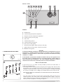
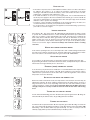
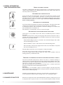
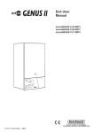
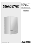
End User
Manual
microCombi 23 MFFI
microCombi 27 MFFI
Leave These Instructions
With the End User
Country of destination: GB / IE
Dear Customer,
Thank you for choosing an ARISTON boiler.
We guarantee that your boiler is a reliable and technically sound product.
This manual provides detailed instructions and recommendations
for proper installation, use and maintenance.
Remember to keep this manual in a safe place for future reference
i.e. by the gas meter.
Your local MTS Servicing Centre is at your complete
disposal for all requirements.
The guarantee on this appliance is valid for 12 months from the first day of installation.
Repairs to the electric, hydraulic or gas circuits may be carried out only by your local
authorised MTS Servicing Centre.
Every attempt has been made to avoid errors of any kind
in this manual, the Management invites customers to inform
of any inaccuracies which they may find.
This will help to improve our service
TABLE OF CONTENTS
1.
2.
3.
4.
5.
6.
GENERAL INFORMATION
page 3
Technical Information
page 3
Control Panel
page 4
OPERATING INSTRUCTIONS
USEFUL INFORMATION AND TROUBLESHOOTING
MAINTENANCE
CHANGE OF GAS TYPE
TIME CLOCK
page 4
page 6
page 7
page 7
page 7
IMPORTANT!
Please read this manual carefully.
For additional information, please consult the “Installation and Servicing Instructions.”
Make sure to keep the manuals provided with the appliance so that they can be used by
the end-user, installer or local service agent.
2
1. GENERAL INFORMATION
MTS (GB) Limited support the
initiative. Your installer will give you, and show
you how to use, a Log Book which will give you important information about your boiler,
and heating system. Please have this Log Book to hand whenever you contact a service
engineer or us.
All CORGI Registered Installers carry a CORGI ID card, and have a registration
number. Both should be recorded in your boiler Logbook. You can check your
installer is CORGI registered by calling CORGI direct on :- (01256) 372300.
This is a combined appliance for the production of Central Heating (C.H.) and Domestic
Hot Water (D.H.W.). This appliance must be used only for the purpose for which it is
designed. The manufacturer declines all liability for damage caused by improper or
negligent use.
Do not allow children or inexperienced persons to use the appliance without supervision.
If you smell gas in the room, do not turn light switches on or off, use the telephone or any
other object which might cause sparks.
Open doors and windows immediately to ventilate the room.
Shut the gas mains tap (on the gas meter) or the valve of the gas cylinder and call your
Gas Supplier immediately.
If you are going away for a long period of time, remember to shut the mains gas tap or
the gas cylinder valve. Consult the Installation and Servicing manual when turning off the
boiler for long periods of time.
Before any intervention within the boiler it is first necessary to isolate the electrical
supply by turning the external switch to “OFF”.
TECHNICAL INFORMATION
GENERAL DATA
Heating input max-min
Heating output max-min
Efficiency at Maximum Thermal Capacity (see
installation instructions)
23 kW
27 kW
kW
kW
%
25.6-11.0
23.7-9.6
92.5
29.3-11.0
27/9.27
92
°C
bar
litres
82-42
3-0.7
6
82-42
3-0.7
6
°C
bar
l/min
l/min
54-36
6-0.2
9.7
2.5
56-36
6-0.2
11.0
2.5
V/Hz
W
IP
230/50
135
X4D
230/50
155
X4D
mbar
mbar
20
29-37
20
29-37
CENTRAL HEATING
Operating Temperature max-min
Maximum-Minimum Heating Pressure
Built-in expansion vessel - Total capacity
DOMESTIC HOT WATER
Temperature of Water for Domestic Use (max-min)
Working pressure max-min
Flow rate ∆T 35°C
Minimum flow rate
ELECTRICAL DATA
Electrical Supply/ Frequency
Power Consumption
Protection of Electrical System
CATEGORY
Nominal Pressure Methane Gas (G20)
Nominal Pressure Liquid Gas (G30-G31)
3
CONTROL PANEL
FR019A
LEGEND:
A - On/Off button
B - Central heating temperature adjustment
C - Domestic hot water temperature adjustment
D - Heating system pressure gauge
E - Time clock
F - Central heating selector
G - Central heating L.E.D. (green)
H - Flue sensor L.E.D. (yellow)
I - Overheat and/or ignition failure (lockout) L.E.D. (red)
J - Ignition failure (lockout) and/or overheat reset button
K - ON/OFF L.E.D. (green)
CAUTION
2. OPERATING INSTRUCTIONS
In the United Kingdom installation, start-up, adjustments and maintenance must be
performed by a CORGI Registered Installer in accordance with the installation
standards currently in effect, as well as with any and all local health and safety
standards i.e.. CORGI.
D
UT009A
In the Republic of Ireland the installation and initial start up of the appliance must
be carried out by a Competent Person in accordance with the current edition of
I.S.813 “Domestic Gas Installations”, the current Building Regulations, reference
should also be made to the current ETCI rules for electrical installation.
E
HELPFUL SUGGESTIONS
To get the most out of your boiler, we have provided you with some useful advice on
proper use and maintenance:
- Periodically check the system pressure using the pressure gauge “D”, make sure that
the pressure is at 1.5 bar when the system is off and cool. If the pressure is below the
minimum recommended value (1 bar), consult your installer for checking and refilling
the system, an example of how a filling loop should be fitted is shown to the left “E”.
NOTE: DO
NOT UNDER ANY CIRCUMSTANCES USE THE APPLIANCE WITH THE PRESSURE GAUGE
READING ZERO.
FILL01
4
- The outer panels of the unit's case must only be cleaned with a damp cloth. Do not use
abrasive cleaners. The control panel can be wiped with either a damp or dry cloth.
Spray polishes must not be used on the control panel surface or knobs. Care must be
taken to prevent any liquid from entering the appliance.
PRACTICAL TIPS
G
F
- If the water is very hard, it is recommended that a water softener or in-line scale reducer
be added to the system so as to reduce the formation of limescale in the boiler
exchangers. This will ensure that the efficiency of the unit remains the same over time,
reducing gas consumption and maintenance costs.
- If the boiler should be out of use for a prolonged period, it is recommended that the
electrical power supply be disconnected and that the external gas cock “F” and “G” be
closed. If low temperatures are expected, the boiler and system pipe work should be
drained in order to prevent frost damage.
- To improve comfort and take full advantage of the heat produced by the boiler, it is
recommended that an external (room) thermostat be installed.
- It is good practice to clean and service the appliance and central heating system every
year. Call a local Service Agent.
IGNITION
K
I
UT002A
Press button “A”. The green L.E.D. “K” will illuminate indicating that the boiler is ready
to operate. The centralised electronic control unit will ignite the burner, upon demand for
either C.H. or D.H.W. If, after approximately 10 seconds, the burner has not ignited, the
boiler safety devices will shut off the gas and the red L.E.D. “I” illuminates. To reset the
ignition system, the reset “J” must be pressed and released. Should the boiler fail to
ignite a second time, check that the external gas cock is open. If the problem persists,
contact a local Service Agent. IMPORTANT!! Always wait 2 minutes before resetting
each time.
WINTER
G
F
UT003A
PROCEDURE
AND SUMMER OPERATING MODES
In the ‘winter operating mode’, the boiler will produce both central heating and domestic
hot water. In the ‘summer operating mode’, the boiler will produce only domestic hot water.
Press “F” button to select winter mode. The green L.E.D. “G” will illuminate.
ADJUSTING THE
B
HEATING
It is possible to set the temperature of the heating system by adjusting the knob “B”.
By positioning the indicator somewhere between 1 and 9, a temperature may be obtained
which varies from approximately 42˚C to about 82˚C.
UT004A
EXTERNAL (ROOM) THERMOSTAT
CONTROL
If an external (room) thermostat is installed, it is recommended that the temperature of
the heating system be set by means of the “B” knob, leaving it at 7-8 position in order to
obtain the best performance from the boiler and to allow the regulation of the external
temperature to function efficiently.
SETTING THE
C
UT005A
HOT WATER FOR DOMESTIC USE
Both in the winter and summer mode, the temperature of the domestic hot water may be
adjusted by using the “C” knob. A delivery temperature for the water may be chosen in a
range from 36˚C to about 54˚C, depending on the flow rate of the water and the position
of the knob between 1 and 9 settings. NOTE: Should the Domestic Hot Water not be hot
enough, it may be necessary to slow the flow rate from the hot water outlet being
used.
G
TURNING
F
UT003A
OFF THE CENTRAL HEATING
To turn off the Central Heating, press the “F” button; the respective green L.E.D. “G” will go off.
The boiler will stay in summer mode, only providing Domestic Hot Water
TURNING
K
UT002A
OFF THE BOILER
To turn the boiler off, press the button “A”; the respective green L.E.D. “K” will go off. Close the
gas cock located under the boiler by inserting a screw driver into the bottom slot (See F & G)
and turning 1/4 turn clockwise until it stops (slot horizontal). It is also necessary to turn the
electricity supply switch (located outside the boiler) to the OFF position.
5
3. USEFUL INFORMATION
AND TROUBLESHOOTING
BOILER
SHUTDOWN SITUATIONS
The boiler is equipped with safety devices that intervene in certain situations and shut it
off. Most of these situations are communicated by means of the L.E.D.s and at times the
user may be able to remedy them.
J
SHUTDOWN
DUE TO IGNITION FAILURE
In the event that the automatic ignition of the burner has failed, the red L.E.D. “I” will
illuminate. In order to reset the ignition, the button “J” must be pressed and released.
Should the boiler fail to ignite a second time, check that the external gas cock is open. If
the problem persists, contact a local Service Agent. IMPORTANT!! Always wait 2 minutes
before resetting each time.
I
J
SHUTDOWN
DUE TO OVERHEATING
In the event that the safety limit is exceeded for the temperature of the water in the boilers
exchanger, the thermostat shuts off the boiler and the red L.E.D. “I” illuminates.
To remedy this situation, wait a few minutes to allow the exchanger to cool down, then
press and release the reset button “J”.
If this situation occurs frequently, contact a local Service Agent.
I
SHUTDOWN
DUE TO INSUFFICIENT WATER CIRCULATION
D
If
UT001A
the boiler is off, one possible cause for this state is an insufficient pressure of water in
the system.
Check the system pressure on the pressure gauge “D” and if it is less than 0.5 bar, repressurise the system as instructed by your installer, should you be unsure some basic
instructions are provided hereafter;
Ensure that the filling loop hose is connected to the cold water inlet pipe and to either
the Central Heating flow or return
Open the handle/s or tap/s to allow water into the Central Heating system
H
Once the needle on the pressure gauge reaches 1 Bar, close the handle/s or tap/s and
disconnect the filling loop hose
Should it still be unclear how to proceed, please consult your installer.
If the boiler does not start up again, contact a local Service Agent.
If there are frequent drops in pressure within the system, have a plumber check the
heating system for possible water leaks.
TEMPORARY
SHUTDOWN DUE TO DEFECTIVE DISCHARGE OF EXHAUST PRODUTS
The boiler is fitted with safety devices, which in the event of a defective discharge of
exhaust products, automatically interrupts the gas supply, thereby shutting off the boiler.
The shut-off of the boiler is temporary and is indicated by the illumination of the yellow
L.E.D. “H” for a period of about 15 minutes.
Once this time period has passed and the discharge state of exhaust system has
returned to normal, the boiler automatically turns back on.
IMPORTANT!
If this situation occurs frequently, contact a local Service Agent so that they may check
that the exhaust fumes are being expelled correctly, that the flue is installed correctly and
that the area is ventilated properly.
4. MAINTENANCE
Schedule an annual maintenance check-up for the boiler with a competent person.
Correct maintenance always results in savings in the cost of running the system.
5. CHANGE OF GAS TYPE
Our boilers are designed to function either with Natural Gas (methane) or LPG gas. If you need
to changeover from one gas to the other, one of our local Service Agents should be contacted.
6
NOTE: the time clock is for Central Heating control only.
The time clock is provided with 96 switches, called riders, each of which covers a time
interval of 15 minutes (four per hour).
When a rider is switched from the inside (off setting) to the outside of the clock border (on
setting), the circuit is closed (switch on) for a period of 15 minutes and then the boiler
starts if the room thermostat (if installed) or the heating thermostat require heat (heating
function on).
6. TIME CLOCK
UT011Ap
EXAMPLE
To set the heating of your home in the time interval from 7.00 am to 9.30 am and from
7.00 pm to 10.00 pm every day:
- rotate the outer ring of the clock in a clockwise direction until the correct time of day
(24h) lines up with the arrow on the clock (at approx. 2 o’clock position);
- under no circumstances should the minute hand be moved manually;
- make sure all the switches, i.e. the riders, are placed on the inside of the clock border;
- pull outward the riders for 7.00 am and 9.30 am, and then all riders between these two;
- repeat this for 7.00 pm and 10.00 pm.
Other heating intervals may be set in the same way.
The clock is provided with a selector switch with three positions (see figure):
1. Position “I” CONSTANT: in this position, the clock circuit is always closed (switch on),
therefore the boiler will constantly be on and will only shut off upon the request of the
room thermostat (if installed) or the heating thermostat;
UT014A
2. Position “O” HEATING OFF: in this position, the clock circuit is always open (switch off)
and the boiler will therefore never ignite for heating;
UT014A
3. “Central” Position PROGRAMMING ACTIVE: in this position, the programme set by
the user is active.
UT014A
TECHNICAL DATA
Ambient
temperature: - 10°C to + 55°C
Shortest
switching time: 15 minutes
Programmable: Every 15 minutes
7
Merloni TermoSanitari SpA - Italy
Commercial subsidiary:
MTS (GB) LIMITED
MTS Building
Hughenden Avenue
High Wycombe
Bucks HP13 5FT
Telephone: (01494) 755600
Fax: (01494) 459775
Internet: www.ariston.co.uk
E-mail: [email protected]
Technical Service Hot Line: (01494) 539579
Cod. 2399841567111 - Edition 1 Revision 1 - 11/07/03
Manufacturer: