1
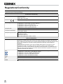
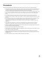
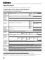
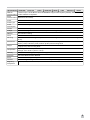
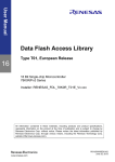
Addendum Sheet
In-Sight® Micro Series Vision System Installation Manual
The In-Sight® Micro series of vision systems now includes the In-Sight 1402. This addendum includes hardware
specifications to support this vision system, along with updates and corrections to existing precautions and
regulations/conformity information. This information will be included in the next revision of the In-Sight® Micro Series
Vision System Installation Manual. Please keep this addendum with your installation manual.
1
Regulations/Conformity
Note: For the most up-to-date regulations and conformity information, please refer to the In-Sight online support site:
http://www.cognex.com/Support/InSight.
Declaration of Conformity
Manufacturer
Cognex Corporation
One Vision Drive
Natick, MA 01760 USA
Declares this
-marked Machine Vision System Product
Product Type
In-Sight Micro 1020/1050/1100/1110/1400/1410: Type 821-0043-1R
In-Sight Micro 1100C/1400C: Type 821-0044-1R
In-Sight Micro 1402: Type 821-0078-1R
In-Sight Micro 1403/1413: Type 821-0047-1R
In-Sight Micro 1403C: Type 821-0048-1R
Complies With
2004/108/EC Electromagnetic Compatibility Directive
Compliance Standards
EN 55022:2006 + A1:2007 Class A
EN 61000-6-2:2005
European Representative
COGNEX INTERNATIONAL
Immeuble “Le Patio”
104 Avenue Albert 1er
92563 Rueil Malmaison Cedex - France
FCC
FCC Part 15, Class A
This device complies with Part 15 of the FCC Rules. Operation is subject to the following
two conditions: (1) this device may not cause harmful interference; and (2) this device must
accept any interference received, including interference that may cause undesired
operation.
This equipment generates, uses, and can radiate radio frequency energy and, if not
installed and used in accordance with the instruction manual, may cause harmful
interference to radio communications. Operation of this equipment in a residential area is
likely to cause harmful interference in which case the user will be required to correct the
interference at their own expense.
KCC
In-Sight Micro 1020/1050/1100/1110/1400/1410: CGX-ISM1400-00(A)
In-Sight Micro 1100C/1400C: CGX-ISM1400-C00(A)
In-Sight Micro 1402: KCC-REM-CGX-ISM1402-01
In-Sight Micro 1403/1413: CGX-ISM1403-00(A)
In-Sight Micro 1403C: CGX-ISM1403-C00(A)
NRTL
TÜV SÜD AM SCC/NRTL OSHA Scheme for UL/CAN 60950-1.
CB
TÜV SÜD AM, IEC/EN 60950-1. CB report available upon request.
RoHS
RoHS 6 Compliant.
Safety and Regulatory
2
Precautions
Observe these precautions when installing the vision system to reduce the risk of injury or equipment damage:
l
An IEEE 802.3af compliant, and UL or NRTL listed, Power over Ethernet (PoE) power source rated Class 0, 2, 3
or 4 must be used. Any other voltage creates a risk of fire or shock and can damage the In-Sight vision system
components. Applicable local and national wiring standards and rules must be followed.
l
To reduce the risk of damage or malfunction due to over-voltage, line noise, electrostatic discharge (ESD), power
surges, or other irregularities in the power supply, route all cables and wires away from high-voltage power
sources.
l
Do not install In-Sight vision systems where they are directly exposed to environmental hazards such as
excessive heat, dust, moisture, humidity, impact, vibration, corrosive substances, flammable substances, or static
electricity.
l
Do not expose the image sensor to laser light; image sensors can be damaged by direct, or reflected, laser light.
If your application requires the use of laser light that may strike the image sensor, a lens filter at the
corresponding laser's wavelength is recommended. Contact your local integrator or application engineer for
suggestions.
l
The In-Sight vision system does not contain user-serviceable parts. Do not make electrical or mechanical
modifications to In-Sight vision system components. Unauthorized modifications may void your warranty.
l
Changes or modifications not expressly approved by the party responsible for regulatory compliance could void
the user’s authority to operate the equipment.
l
Service loops should be included with all cable connections.
l
Cable shielding can be degraded or cables can be damaged or wear out more quickly if a bend radius or service
loop is tighter than 10X the cable diameter.
l
Class A Equipment (broadcasting and communication equipment for office work): Seller and user shall be
notified that this equipment is suitable for electromagnetic equipment for office work (Class A) and can be used
outside the home.
l
This device should be used in accordance with the instructions in this manual.
3
Specifications
The following sections list general specifications for the In-Sight Micro vision systems.
In-Sight Micro Vision System Specifications
Table 4-1: In-Sight Micro Vision System Specifications
Specifications
1020/1050
1100/1110
1100C
1400/1410
1400C
1402
In-Sight
version
4.6.0
1403/1413
1403C
Minimum
Firmware
Requirement
In-Sight version 4.4.3
In-Sight version 4.4.3
Job/Program
Memory
128MB non-volatile flash memory; unlimited storage via remote network device.
Image
Processing
Memory
256MB
Sensor Type
1/3-inch CCD
1/1.8-inch 1/1.8-inch CCD
CMOS
Sensor
Properties
5.92mm diagonal, 7.4 x 7.4µm sq. pixels
8.7mm
8.8mm diagonal, 4.4 x
diagonal, 4.4µm sq. pixels
5.3 x
5.3µm sq.
pixels
Resolution
(pixels)
640 x 480
1280 x
1024
Electronic
Shutter Speed
16µs to 1000ms
Acquisition
Rapid reset, progressive scan, full-frame integration.
Bit Depth
256 grey levels (8
bits/pixel)
Image
Gain/Offset
Controlled by software.
Frames Per
Second1
60 full frames per second 58 full
frames per
second
Lens Type
CS-mount and C-mount (with 5mm extension, included).
Image Sensor
Alignment
Variability2
±0.127mm (0.005in), (both x and y) from lens C-mount axis to center of imager.
Trigger
1 opto-isolated, acquisition trigger input. Remote software commands via Ethernet. (RS-232C
available when using the optional CIO-MICRO or CIO-MICRO-CC I/O module.)
Discrete Inputs
None. (Eight additional inputs available when using the optional CIO-MICRO or CIO-MICRO-CC I/O
module.)
Discrete
Outputs
2 opto-isolated, NPN/PNP high-speed outputs. (Eight additional outputs available when using the
optional CIO-MICRO or CIO-MICRO-CC I/O module.)
Status LEDs
Network, 2 user-configurable.
1600 x 1200
52µs to 1000ms
24 bit color
256 grey
levels (8
bits/pixel)
24 bit
color
256 grey levels (8
bits/pixel)
24 bit color
60 full
frames per
second
58 full
frames
per
second
60 full
14 full
frames per frames per
second
second
7 full frames
per second
1 Maximum frames per second is job-dependent and based on the minimum exposure for a full image frame capture.
2 Expected variability in the physical position of the image sensor, from vision system-to-vision system. This equates to ~ ±17 pixels on a 640 x
480 resolution CCD, ~ ±24 pixels on a 1280 x 1024 resolution CMOS and ~ ±29 pixels on a 1600 x 1200 resolution CCD.
4
Specifications
1020/1050
1100/1110
1100C
1400/1410
1400C
1402
1403/1413
1403C
Network
1 Ethernet port, 10/100 BaseT with auto MDI/MDIX. Supports DHCP (factory default), static and linkCommunication local IP address configuration.
Serial
None. (RS-232C: 4800 to 115,200 baud rates when connected to the optional CIO-MICRO or CIOCommunication MICRO-CC I/O module).
Power
Class 2 Power over Ethernet (PoE) device.
Power Type
A and B.
Power
Consumption
6.49 W maximum per Class 2 PoE.
Current
Per Class 2 PoE requirements.
Voltage
48 V nominal, applied from a Class 2 PoE injector which is typically powered from some other voltage.
Material
Die-cast zinc housing.
Finish
Painted
Mounting
Four M3 threaded mounting holes (1/4 - 20 and M6 mounting holes also available on mounting
block).
Dimensions
30mm (1.18in) x 30mm (1.18in) x 60mm (2.36in) without mounting block.
30mm (1.18in) x 38.2mm (1.50in) x 60mm (2.36in) with mounting block.
Weight
121g (4.27oz.) without mounting block.
146g (5.15oz.) with mounting block.
Temperature
Operating: 0°C to 45°C (32°F to 113°F)
Storage: -30°C to 80°C (-22°F to 176°F)
Humidity
90%, non-condensing (Operating and Storage)
Protection
IP51 with cables and lens attached.
Shock
80 G shock with 50 gram or lighter lens attached per IEC 68-2-27 EA.
Vibration
10 G with 50 gram or lighter lens attached 2 hrs/axis (10-500 Hz) per IEC 68-2-6, FC.
Regulatory
Compliance
CE, FCC, KCC, TÜV SÜD NRTL, RoHS
5
Acquisition Trigger Input
Table 4-2: Acquisition Trigger Input Specifications
Specification
Voltage
Current
Delay1
Description
ON
OFF
ON
OFF
Resistance
In-Sight Micro 1020, 1050, 1100,
1100C, 1110, 1400, 1400C,
1402 & 1410
In-Sight Micro 1403 & 1413
In-Sight Micro 1403C
20 to 28V (24V nominal)
0 to 3V (8V nominal threshold)
2.0 to 2.9mA
< 250µA
~10,000 Ohms
63µs maximum latency between leading edge of trigger and start of
acquisition. Input pulse should be minimum of 1 ms wide.
81µs maximum latency between leading edge of trigger and start of
acquisition. Input pulse should be minimum of 1 ms wide.
116µs maximum latency between leading edge of trigger and start of
acquisition. Input pulse should be minimum of 1 ms wide.
The acquisition trigger input is opto-isolated. To trigger from an NPN (pull-down) type photoelectric sensor or PLC
output, connect pin 3 (TRG+) to +24V and connect pin 4 (TRG-) to the output of the photoelectric sensor.
When the output turns ON, it pulls TRG- down to 0V, turning the opto-coupler ON. To trigger from a PNP (pull-up)
photoelectric sensor or PLC output, connect pin 3 (TRG+) to the output of the photoelectric sensor and connect pin 4
(TRG-) to 0V. When the output turns ON, it pulls TRG+ up to 24V, turning the opto-coupler ON.
Figure 4-1: Acquisition Trigger Input Schematic
P/N 597-0136-01
Printed in the USA
1 Maximum latency is based on a 1µs trigger debounce.
6