1
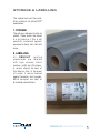
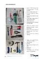
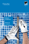
installation
Manual
renolit waterproofing
EXCELLENCE IN ROOFING
RENOLIT WATERPROOFING
1
There are bound to be questions
if you don’t know, don’t guess, ASK!
Call:
Training Manager
PAUL KENT - 07831 113599
Technical Manager
DAVID DAVIS - 07774 107758
Area Executives
South East:
GARY HUGHES - 07879 445222
South West:
MALCOLM HEAVENS - 07774 107759
South Central
CHRIS LEE - 07876 742025
Northern Area & Scotland
STEPHEN BADDELEY - 07872 194488
North East
TOM VAN-HUCK - 07774 148325
North West
NEIL SANDERS - 07769 883970
RENOLIT Sales Office: 01234 244230
[email protected] - www.alkorproof.com
2
RENOLIT WATERPROOFING
RENOLIT WATERPROOFING
INDEX
Help, Contact Numbers
P 2
Storage & Labelling
P 5
Equipment
P 6
Compatibility & Cleaning
P 7
Hot air Welding – Checks, Temperature & Testing
P 9
Welding – Overlaps - Welding Gun
P 10
Welding Check & Seam Sealer
P 11-12
Automatic Welding, Weld Test
P 13
Solvent Welding
P 14-15
alkorPLAN® F, Mechanically fastened System; VCL & insulation P 16
P 17-19
Roof Sheet - Fasteners - alkorPLUS® metalsheet
Butt Straps, T Joints, End Joints P 20-21
Upstands, Drip Edges
P 22
Corners
P 23
Repairs
P 24
Welds
P 25
P 26-27
alkorPLAN® A - Adhered system
P 28
alkorPLAN® L – Loose laid & Ballasted System
P 30
alkorPLAN®, alkorFLEX®, alkorTOP®
Pipe Penetrations, uPVC fittings, Profile System
P 31-32
Accessories
P 32
Details for Mechanical Fastening
P 34-47
Details for Loose laid & Ballasted
P 48-53
Details for Adhered
P 54-59
General Details
P 60-67
Summary of Measurements Back page
RENOLIT WATERPROOFING
3
NBS
SERVICES
The information contained in the present commercial literature has been given in good faith and with the intention of providing information.
It is based on current knowledge at the time of issue, and may be subject to change without notice. Nothing contained herein may induce
the application of our products without observing existing patents, certificates, legal regulations, national or local rules, technical approvals
or technical specifications or the rules and practices of good workmanship for this profession.The purchaser should verify whether import,
advertising, packaging, labelling, composition, possession, ownership and the use of our products or the commercialisation of them
are subject to specific territorial rules. He is also the sole person responsible for informing and advising the final end user. When faced
with specific cases or application details not dealt with in the present guidelines, it is important to contact our technical services, who
will give advice, based on the information at hand and within the limitations of their field of expertise. Our technical services cannot be
held responsible for the conception of, nor the execution of the works. In the case of negligence of rules, regulations and duties on the
part of the purchaser we will disclaim all responsibility. The colours respect the UV resistance required by EOTA, but are still subject to
the natural change over time. Are excluded from the guarantee: aesthetic considerations in case of partial repair of deficient membrane
covered by the guarantee.
www.aLKORpROOf.COM
10 Y
E
NT
O
LI
TW
RO
ATERP
O
N
4
FI
NG
Y
RE
The British Board of Agrément
have assessed the life
expectancy of alkorPLAN® F
used in the United Kingdom to
be in excess of 30 years.
WARR
A
AR
alkorPLAN® roofing products
and Systems have a standard
guarantee of 10 years, and
are installed by approved
contractors and installers who
are trained and assessed
by RENOLIT.
All RENOLIT waterproofing
membranes for roofing are
part of the RoofCollect®
collection and recycling
programme.
RENOLIT WATERPROOFING
The RENOLIT division
responsible for the roofing
activity has been approved to
EN ISO 9001:2000.
sTORagE & LabELLINg
This manual sets out the installation methods for alkorPLAN ®
membranes.
1. STOrAGE
The rolls are delivered to site on
pallets. These should be stored
in a dry place or, if this is not
possible, protected against
exposure to damp, rain, frost and
snow.
2. LABELLING
All rENOLIT roofing
membranes are labelled
w i t h t y p e n u m b e r, b a t c h
number, width and thickness.
A record should be kept of
this label so that, in the event
of a claim, it can be checked
against laboratory test samples.
Batch samples are kept of
all material manufactured.
RENOLIT WATERPROOFING
5
EQUIpMENT
• L eister TRIAC manual hot
air welding gun, 110 volt
or similar.
• 20 mm nozzle for detail work.
• 4 0 mm nozzle for seam
welding.
•40mmsiliconerollerformost
welding.
• 6 mm brass corner roller to
weld awkward details.
• Weldtestingprobe
• Woodentemplateforwelding
into right angles
• T o o l s f o r L e i s t e r m a i n tenance–brushes, screwdrivers, grips.
• Small (2inch) soft brush for
welding gun filter maintenance
• W i r e b r u s h f o r n o z z l e
cleaning
• To o l s f o r m e a s u r i n g ,
marking and cutting
• Tapemeasure
• Scissors
• Retractable bladed craft
knife
• Markerpen
• Stringline
• T i n s n i p s f o r c u t t i n g
alkorPLUS® metalsheet
6
RENOLIT WATERPROOFING
COMpaTIbILITy
CHEMICAL
COMPATIBILITY
Please check the data sheet
for general information on
the chemical compatibility of
alkorPLAN® roofing membranes.
INSULATION
As a general rule all synthetic
insulation boards must have a
separation layer either included
during manufacture or laid before
installing the membrane.
BITUMEN PrODUCTS
alkorPLAN ® must not be laid in
direct contact with any bitumen
product. A separation layer must
be used.
OTHEr PVC MEMBrANES
Or OTHEr FLExIBLE PVC
PrODUCTS
alkorPLAN ® must not be laid in
direct contact with, or welded
to other plasticised PVC membranes. As a general rule,
alkorPLAN ® membranes should
not be laid over old synthetic
or rubber membranes. These
membranes should be removed.
RENOLIT WATERPROOFING
7
CLEaNINg
CLEANING
Cleaning is best done with a rag.
If dirt is to be removed, use
a spray with water and a
diluted detergent with water or
alkorPLUS®cleaner.Ifbituminous
products have to be removed from
the membrane only alkorPLUS ®
cleaner may be used.
8
RENOLIT WATERPROOFING
HOT aIR WELDINg, TEMpERaTURE &
TEsTINg
HOT AIr WELDING
Preliminary checks ensur
the nozzle is clean and
open across its entire width.
Ensure the filter is cleaned.
TEMPErATUrE
Adjust the welding temperature in
the hand held welding gun to allow
a flow of hot air that induces a
slow charring on a piece of wood.
If the welding gun has an
internal heat setting with digital
thermometer display, set this to
480 deg C and allow the gun ten
minutes to heat up. This may be
adjusted depending upon ambient
conditions.
WELD TESTING
Make a weld sample to test the
material you will be using and
to test that the settings on your
welding gun are correct.
Check the weld test sample with
adestructivetest.(seetestingon
Page13)
RENOLIT WATERPROOFING
9
CABLES & WELD OVERLAPS
Cables
To avoid a voltage drop, never
use an excessively long extension cable or share a power cable
with others.To prevent damage
and fire, never use an extension
cable that is still coiled on a roll.
Weld OveRlaps
As a general rule, alkorPLAN ®
weld overlaps must be 100 mm
on mechanically fastened
systems, 80 mm on adhered
systems and 50 mm on ballasted
systems. It is important to have
a constant weld width of min.
30 mm.
10
RENOLIT WATERPROOFING
WELDINg gUN & WELDINg CHECK
WELDING GUN
The weld is now carried out
with the hot air welding gun
held between the sheets of
alkorPLAN ® to be welded at 45°
to the welding line.
Roll the weld with the silicone
roller held about 1 cm from the
nozzle of the gun. The operative
has three factors at his control:
The HEAT of the welding gun
The SPEED at which the welding
gun is moved
The PrESSUrE of the roller on
the two alkorPLAN® sheets
WELDING CHECK
On completion of the weld the
operative must check its integrity
by drawing a weld checking probe
down the length of the weld. The
probe will find any unwelded
areas which must be re-welded
immediately with hot air.
RENOLIT WATERPROOFING
11
sEaM sEaLER
SEAM SEALEr
When an area of welding is
completed and checked the
alkorPLAN ® seam sealer must
be applied. Ensure that the
membrane is clean and dry and
dust free before the application
of the seam sealer. It is good
practice to apply the seam
sealer as soon as possible after
the welding is completed and
checked although care must be
taken not to apply seam sealer
to areas that will have further
membrane welded to them.
12
RENOLIT WATERPROOFING
aUTOMaTIC WELDINg & WELD TEsT
AUTOMATIC WELDING
There are various automatic
welders on the market.
The manufacturer’s representatives will be available, on
request, to set up the machines
and train operatives in their
use - especially when buying
a new machine. Please check
with our technical dept. for the
required weld widths approved
for the various machines.
WELD TEST
When hot air welding with hand
or automatic tools it is good
practice to carry out a peel test
before every welding session on
a 50 mm wide sample weld, so
as to ensure that the tool settings
arecorrect.Iftheweldhasbeen
made correctly the membrane will
give way before the weld.
A 50 mm wide weld should
support a weight of at least
15 kgs.
RENOLIT WATERPROOFING
13
sOLVENT WELDINg
& sOLVENT bRUsH
SOLVENT WELDING
alkorPLAN ® can also be solvent
welded but this can only be used
for long seams, NOT for any detail
work & strict criteria must be
obeyed before the use of solvent
welding can be approved.
•T he air temperature must
be above 5 deg centigrade
•Relativehumidity<60%
•I t may only be used for
welding new alkorPLAN®
•ThealkorPLAN® must be clean,
dry & dust free & laying flat.
Check the expiry date of the
solvent. Do not use old solvent or
solvent that has been opened at
an unknown date.
Do not stand the solvent brush
applicator on the membrane.
SOLVENT BrUSH
The solvent is applied using a
brush applicator between the
sheets to be welded. The brush
applicator is moved in a circular
motion applying the minimum
amount of solvent to both sheets
being welded.
14
RENOLIT WATERPROOFING
sOLVENT WELDINg CONT.
SOLVENT WELDING CONT.
Immediately following the brush
applicator, a rolled rag is used to
apply pressure to the welded joint,
smoothing it out and expelling any
excess solvent.
As the welding progresses a weight
(e.g.sandbag)isplacedalongtheline
of the weld to give a short period of
constant pressure until the adjacent
welded area is completed. The weld
must be checked as before, using
the weld checking probe and any
unwelded areas sealed using hot air
welding techniques.
Aweldtestmustbeincluded.Itis
good practice to carry out a peel test
before every welding session on a 50
mm wide sample weld, to ensure that
the welding process is correct.
If the weld has been made correctly, the membrane will give way
before the weld. A 50 mm wide weld
should support a weight of at least
15 kg. Testing after 1 hour curing.
SOLVENT WELDING CANNOT BE USED TO rEWELD
UNWELDED ArEAS WHEN
SOLVENT WAS USED
INITIALLY.
Seam sealer is then applied to the
finished areas.
RENOLIT WATERPROOFING
15
f - THE fIXED sysTEM
VapOUR CONTROL LayER
& INsULaTION
THE FIxED SYSTEM
alkorPLAN ® F is the most
common system used when
installing rENOLIT roofing
membranes. It is usually laid
on a trapezoidal metal deck.
VAPOUr CONTrOL
LAYEr & INSULATION
Vapour Control Layer is laid over
themetaldeck.Itisoverlapped
by a minimum of 100 mm and
sealed.
The specified thickness of
insulation board is laid in a “breakbonded” style and fixed according
to the wind loading calculations
and the manufacturers approved
fixing system.
At terminations, the VCL is
taken up and sealed to details
and penetrations in accordance
with Part L2 of the UK Building
Regulations.
16
RENOLIT WATERPROOFING
f - ROOfINg sHEET
rOOFING SHEET
NOT OK
The alkorPLAN® roofing
membrane is laid at 90 degrees to the deck direction.
OK
The alkorPLAN ® roofing membrane has two lines printed along
the edge during the manufacturing
process. The first line is the
centre line for the fasteners and
the second line is the extent of
the overlap of the adjacent sheet
of alkorPLAN ®. This is known as
the weld line.
There must always be a minimum
of 10 mm between the edge
of the pressure plate and the
edge of the alkorPLAN ® roofing
membrane.
RENOLIT WATERPROOFING
17
fasTENERs
& alkorpLUs® metalsheet EDgE DETaILs
FASTENErS
The pressure plates are spaced
according to the wind loading
calculation but not closer than
twice the length of one plate.
A minimum of 2 fasteners
per m² must be respected
at all times. Only approved
fasteners shall be used. If in
doubt contact our technical
department. When installing
the pressure plates ensure
that they are not over tightened.
The pressure plates work in a
different way from those used
to fix the insulation board.
When installed correctly they
should move when twisted firmly
with the thumb and forefinger.
A fastener that is over tightened
becomes ineffective and places
greater strain on the adjacent
screws. Over tightened screws
must be replaced.
18
RENOLIT WATERPROOFING
alkorpLUs® metalsheet EDgE DETaILs
ALKOrPLUS® METALSHEET EDGE DETAILS
At the perimeter of the roof the
alkorPLUS ® metal profiles are
used to terminate the alkorPLAN®
roofing membrane. They are
prefabricated to the required
profile for each job and are
cut and bent on site to fit the
edge detail of the roof.
The alkorPLUS ® metal profiles
are fixed with a waterproof
joint before the installation of
the main alkorPLAN ® roofing
membrane. Unless otherwise
advised, the metal profile is fixed
using self tapping screws at
250 mm centres with the first fixing
50 mm from the end of the profile.
The alkorPLUS ® metal profiles
are fixed leaving a minimum
5 mm gap between each profile.
The gap is covered with a 50 mm
wide Aluband tape. This gives a
50 mm wide unwelded gap
between sections which allows
a sufficient area of membrane
for expansion and contraction
movement in the joint.
A 200 mm wide strap of
alkorPLAN ® is then welded over
the joint to form a waterproof
edge detail for the termination of
the alkorPLAN® field sheet.
RENOLIT WATERPROOFING
19
bUTT sTRaps
T JOINTs & CapILLaRIEs
BUTT STrAPS
Care must be taken to ensure
that alkorPLAN ® membrane is
securely welded into the right
angle corners of upstands.
Ifbuttstrapisspotweldedinto
position and these right angle
welds are carried out first, this will
ensure that the joint is waterproof.
After welding, the joint must be
checked but the seam sealer
must wait until the field sheet
hasbeeninstalled.Itisnotgood
practise to weld alkorPLAN ®
roofing membrane over seam
sealer.(AxonM1,Page34)
T JOINTS & CAPILLArIES
Where the alkorPLAN ® field
sheet runs across a butt strap
a “T” joint will be created. The
weld over the capillary should
be firmly welded using the
6 mm brass roller, before the
weld between membrane and
alkorPLUS® metalsheet is
completed.
20
RENOLIT WATERPROOFING
END JOINTs
END JOINTS
End joints of subsequent rolls of
alkorPLAN ® roofing membrane
must be cleaned to remove any
tape or adhesive used in the
rolling of the membrane and then
must be overlapped by 250 mm
and then welded in the normal
way. The end joints across the
roof must be staggered to give
a minimum of 500 mm between
each joint.
Exposed corners of
alkorPLAN ® roofing membrane
field sheet must be rounded.
Ensure that the diameter of this
rounded effect on the corner is
same over the whole roof. This will
give the roof a neat appearance.
RENOLIT WATERPROOFING
21
DIRECTION CHaNgEs & UpsTaNDs
DRIp EDgEs
DIrECTION CHANGES &
UPSTANDS
Where the roof shape changes
from a horizontal plane to an
angled or vertical plane, a section
of alkorPLUS ® metal profile
must always be used to facilitate
this change of direction. The
alkorPLAN® roofing membrane is
cut to fit the horizontal alkorPLUS®
metalsheet plane and welded
to it in the normal way. The
alkorPLUS ® metalsheet follows
the change of direction and
alkorPLAN® membrane is cut to fit
the vertical leg of the alkorPLUS®
metalsheet section and welded to
it. When a right angled section of
alkorPLUS® metalsheet is installed,
it must only be fastened to the
substrate, in the horizontal plane.
(AxonM2Page35;DetailF1,Page
36)
The spacing beween intermediate profiles is 500 mm.
The intermediate profile can
be substituted by gluing the
alkorPLAN® membrane to the roof
substrate. The alkorPLUS ®81040
contact glue must be applied on
both sides.
(2x150g/m²consumption).
22
RENOLIT WATERPROOFING
CORNERs
DrIP EDGES
Compressive foam tape must be
used to seal the drip edge to the
galvanised profile and substrate
to prevent wind ingress.
COrNErS
Corners are formed by cutting
and welding the areas of roofing
sheet to the point of the corner
and welding a prefabricated
internal or external corner piece
over the point where the roofing
sheets meet. Care must be
taken when installing corners
to ensure that the membrane
is welded into the point of the
corner. If the corner piece is
spot welded into position and
the point of the corner is welded
first, this will ensure that the
corner will be waterproof when
the rest of the welding has been
carried out.
RENOLIT WATERPROOFING
23
DaMagE & REpaIRs
DAMAGE & rEPAIrS
Damage to membrane must be
repaired using welded patches.
Ensure the area is clean and dry.
The patches must be cut to allow
a minimum welded width of 50
mm and a 50 mm gap between
the damage and the edge of the
patch. Hence the smallest patch
to repair a pinhole would be 200
mm in diameter.
It is good roofing practise to
disguise patches.
The customer does not want
a new roof with patches in it.
For patches in a new roof, cut
the required length from a full
width roll of alkorPLAN ® roofing
membrane and weld this piece
into position as if it were a roll
end. Round the corners in the
normal way.
24
RENOLIT WATERPROOFING
WELDs
WELDS
With the hot air welding gun, the
installer must endeavour to form
a 50 mm wide weld using the
fish tail nozzle. The welding must
be continuous and have no air
inclusions. Narrow welds will be
condemned.
Hot air welding can be used on all
areas to be waterproofed.
Solvent welding can only be
used on the lap joints of new
alkorPLAN ® roofing material and
then only when the conditions
areappropriate(seeearlier,under
solventwelding).
RENOLIT WATERPROOFING
25
a - THE aDHERED sysTEM
THE ADHErED SYSTEM
The alkorPLAN ® A system uses
alkorPLUS 81068 PU glue to glue
the alkorPLAN ® fleece backed
membrane to the substrate of
theroof.Itisappliedfromsingle
can or from a number of cans
mounted on an applicator trolley.
The amount of glue to be used
is specified by the wind load
calculation carried out by a
qualified engineer.
When the adhesive is applied in
lines, as illustrated, it must be
squeegeed across the width of
the membrane to create a full
bond.
26
RENOLIT WATERPROOFING
a - THE aDHERED sysTEM
The installation of the alkorPLAN®
A system differs from the
alkorPLAN® F, fixed system in one
important way. The alkorPLUS ®
metal profiles are installed, fixed
and water-proofed over the
installed alkorPLAN® roof sheet.
The junction between alkorPLUS®
metalsheet profile and roofing
sheet is then waterproofed by a
cover strap, welded to both in the
approvedmanner.(AxonA3Page
56;DetailA3page57)
Corners, vents and pipes are
installed using the same methods
as for the alkorPLAN® F system.
The alkorPLUS ® metal perimeter
roof terminations are waterproofed
as described in the alkorPLAN® F
system but, as detailed above,
fixed over the membrane and
waterproofed.
RENOLIT WATERPROOFING
27
L - THE LOOsE LaID aND
baLLasTED sysTEM
THE LOOSE LAID AND
BALLASTED SYSTEM
The alkorPLAN ® used in this
system is specially formulated for
use in the extreme environments
caused when the membrane is
covered and held down using a
ballastedrestrainingsystem.Itis
glass-fibre reinforced to give extra
dimensional stability.
Do NOT attempt to use other
types of membrane for this
application.
28
RENOLIT WATERPROOFING
L - THE LOOsE LaID aND
baLLasTED sysTEM
The essential difference
with this system is that the
alkorPLAN® roofing sheet
is loose laid. The welded
seams and edge restraints are
carried out as described in
the alkorPLAN ® F system.
T h e ro o f i n g s h e e t i s p ro t e c t e d b y a P V C / f l e e c e
laminate where corner support
pads and paving slabs are
employed.
RENOLIT WATERPROOFING
29
RENOLIT produce four different
roofing membranes:
Plasticised PVC
CPE – Chlorinated
Polyethylene
TPO – Thermoplastic
Polyolefin
TEC
EVA/EBA - Ethylene/Vinyl Acetate Ethylene/Butyl Acrylate
These are all different chemical
compounds
THEY ARE NOT
COMPATIBLE
This Manual is produced for
alkorPLAN ® installation. Should
you require further training on the
other products, please contact
the RENOLIT Technical dept.
30
RENOLIT WATERPROOFING
pIpE pENETRaTIONs
U-pVC fITTINgs
PIPE PENETrATIONS
Penetrations through the roofing
sheet such as pipe outlets,
supports for air handling units,
posts for Mansafe systems, etc.
are waterproofed with a patch of
alkorPLAN® membrane stretched
over the obstruction, and welded
to a collar of membrane around
the penetration. This is then
waterproofed with seam sealer
and/or a stainless steel clip.
(DetailG4,Page65)
U-PVC FITTINGS
alkorPLAN® can be hot air welded
directly to rooflights, outlets,
pipes and roof fittings made from
unplasticised PVC. (Axon G1
Page60;DetailG1Page61)
RENOLIT WATERPROOFING
31
pROfILE sysTEM
aCCEssORIEs
PrOFILE SYSTEM
Extruded profiles can be welded
to alkorPLAN® roofing membrane
to simulate lead, zinc, aluminium
and copper standing seam roofs.
The 3 meter lengths are spot
welded into position and then
the base of the A cross section is
welded to the roof sheet.
ACCESSOrIES
There is a full range of alkorPLAN®
& alkorPLUS® accessories:
•Internalandexternalpreformed
corners.
•a lkorPLUS ® metalsheet PVC/
Steel laminate
•Bottlesforseamsealer and welding fluid.
•Solvents,cleanersand
adhesives
•Seamsealer
32
RENOLIT WATERPROOFING
aCCEssORIEs
•Weldingprobes.
•Weldingbrushes.
•Extrudedprofile
•alkorPLAN® protection layers.
•alkorPLAN® walkway.
(DetailF5,Page42;
DetailF6,Page43)
•Pipeoutletsflexibleand
stainless Steel and grills.
(AxonG2,Page63;
Detail G2, Page 62;
DetailG3,Page64)
RENOLIT WATERPROOFING
33
F
34
RENOLIT WATERPROOFING
alkorPLAN® membrane welded to
alkorPLUS® metalsheet and over joint
200 mm wide strip of alkorPLAN®
membrane with min. 30 mm solvent/
heat welds
alkorPLUS® aluminium strip 50 mm wide
alkorPLUS® metalsheet with 5 mm max gap
between to allow for movement
Axonometric M1
alkorPLUS® metalsheet Section Joints
alkorPLUS® metalsheet sections are mechanically fastened leaving a 3 to 5 mm max. gap to allow for thermal movement.
A strip of 50 mm wide Aluminium Tape is applied over the gap to create an unwelded area.
This is then covered with 200 mm wide alkorPLUS® Junction Strip welded to the two metal sections with minimum 30 mm welds.
The alkorPLAN® roofing sheet is then welded to alkorPLUS® metalsheet sections and junction strip.
Details for Mechanical Fastening
RENOLIT WATERPROOFING
35
F
Steel decking
alkorPLUS® vapour control layer
Insulation
alkorPLAN® membrane welded to alkorPLUS®
metalsheet angle
alkorPLUS® metalsheet angle mechanically
fastened @ 250 mm cs on horizontal section only
alkorPLUS® metalsheet strips @ 500 mm cs
mechanically fastened @ 200 mm cs
alkorPLAN® membrane welded onto
alkorPLUS® metalsheet strips
Axonometric M2
Application to Vertical Faces
alkorPLUS® metalsheet strips are mechanically fastened to the vertical substrate at intervals of 500 mm. alkorPLAN® membrane is
welded to the alkorPLUS® metalsheet strips to form a fully supported vertical waterproof detail.
36
RENOLIT WATERPROOFING
F
alkorPLUS® vapour control layer
Insulation
alkorPLAN® membrane
alkorPLUS® sealer
alkorPLUS® metalsheet angle
welded joint
alkorPLAN® membrane
Detail F1
Typical Upstand Detail
alkorPLUS® metalsheet angle is mechanically fastened to the substrate around the base of the upstand.
alkorPLAN® membrane is then welded to the alkorPLUS® metalsheet angle on the horizontal and the vertical faces.
Where the upstand is in excess of 500 mm high then additional support is required to the alkorPLAN® membrane on the vertical
face. For further information refer to Axonometric M2.
RENOLIT WATERPROOFING
37
F
Profiled metal deck
Insulation
alkorPLUS® vapour control layer
alkorPLAN® membrane
alkorPLUS® seam sealer
100 mm overlap with welded joint
Mechanical fastening with pressure plate
alkorPLAN® membrane
Detail F2
Mechanically Fixed Seam
alkorPLAN® membrane is rolled out over the prepared roof. The edge is fastened with pressure plates at intervals determined by the
wind loading requirements. The pressure plates are located 10 mm min. from the edge of the alkorPLAN® membrane.
The adjoining roll overlaps the fastened edge by 100 mm min. and is welded to it.
38
RENOLIT WATERPROOFING
F
alkorPLUS® vapour control layer
Insulation
alkorPLAN® membrane
welded joint
alkorPLUS® seam sealer
alkorPLUS® metalsheet upstand
Code ‘4’ lead flashing
alkorPLUS® vapour control layer sealed ‘continuous’
Note:
If wall construction is not insulated block, then insulation will be required to a minimum height of 300 mm.
Detail F3
Typical Wall Abutment
alkorPLUS® metalsheet is mechanically fastened to the substrate forming an upstand against the abutment face.
alkorPLAN® membrane is then welded to the alkorPLUS® metalsheet.
The detail is then finished with a lead or pressed metal cover flashing and pointing.
RENOLIT WATERPROOFING
39
F
Insulation
alkorPLUS® vapour control layer
Steel roof deck
alkorPLAN® membrane
welded joint
alkorPLUS® metalsheet mechanically fastened
to roof decking
Lead or pressed metal cover flashing
Note:
If wall construction is not insulated block, then insulation will be required to a minimum height of 300 mm.
Axonometric F3
Typical Wall Abutment
This view shows how the detail is produced, built up from the steel decking, with the alkorPLUS® vapour control layer and insulation
laid over. The alkorPLUS® metalsheet is mechanically fastened to the decking and the alkorPLAN® membrane is welded onto the
alkorPLUS® metalsheet.
40
RENOLIT WATERPROOFING
F
Roof decking
alkorPLUS® vapour control layer
Insulation
alkorPLUS® metalsheet profile mechanically fastened to deck
alkorPLAN® membrane welded to alkorPLUS® metalsheet profile
Galvanised steel brackets fixed @ 1000 cs
Compressive foam strip
See further details below.
Axonometric F4
Water-Check Kerb
Typically at the exposed head of a mono-pitched roof or along the exposed verges of all pitched roofs there is a requirement to
contain the rainwater run-off. This detail produces a weathered upstand which prevents water spillage and provides a neat finish
to the roof edge.
RENOLIT WATERPROOFING
41
F
Insulation by blockwork contractor
must be sealed against u/s of roof buildup
Insulation
alkorPLUS® vapour control layer
Galvanised metal support pressing
alkorPLUS® seam sealer
alkorPLUS® compressive foam strip
Membrane welded joint
alkorPLAN® membrane
alkorPLUS® metalsheet
Detail F4
Water-Check Kerb
Galvanised steel brackets are fastened at 1000 mm cs along the roof kerb. A compressive foam strip is laid over the brackets and
alkorPLUS® metalsheet profile is mechanically fastened in place. The alkorPLAN® membrane is then welded to the alkorPLUS®
metalsheet.
42
RENOLIT WATERPROOFING
F
welded joint
Profiled metal deck
alkorPLAN® membrane
continuous over walkway
alkorPLUS® sealer
alkorPLAN® membrane walkway 1050 mm wide
alkorPLUS® vapour control layer
Insulation
0.9 mm galvanised steel sheet wrapped in
alkorPLUS® protection fleece secured to decking
mechanical fixings
Detail F5
Walkway (method 1)
Once the installation of the alkorPLAN® membrane is completed, walkway routes can be formed by laying 0.9 mm galvanised
steel sheets which are wrapped in alkorPLUS® protection fleece. This is then covered by 1050 mm wide alkorPLAN® walkway
membrane, the edges of which are welded to the main alkorPLAN® roof membrane.
RENOLIT WATERPROOFING
43
F
welded joint
Profiled metal deck
alkorPLAN® membrane
continuous over walkway
alkorPLUS® sealer
alkorPLAN® membrane walkway 1050 mm wide
alkorPLUS® vapour control layer
Insulation
0.9 mm galvanised steel sheet wrapped in
alkorPLUS® protection fleece secured to decking
mechanical fixings
Detail F6
Walkway (method 2)
The walkway routes are formed by mechanically fastening
0.9 mm galvanised steel sheets which are wrapped in alkorPLUS® protection fleece prior to the installation of the alkorPLAN®
membrane. This is covered by 1050 mm wide alkorPLAN® walkway membrane, the edges of which are welded to the alkorPLAN®
roof membrane.
44
RENOLIT WATERPROOFING
F
See further details below.
200 mm alkorPLAN® junction strip
welded to membrane
Compressive foam strip
Continuous alkorPLAN® membrane folded down
into gap
Movement joint in steel deck
Vapour control layer
Insulation
Axonometric F7
Typical Movement Joint
Although alkorPLAN® reinforced membrane is flexible, modern construction often requires larger movement tolerances to be
allowed for at specifically designed movement joints. alkorPLAN® junction strip has the strength and elasticity to cope with these
conditions.
RENOLIT WATERPROOFING
45
F
alkorPLUS® vapour control layer
Insulation
Rivet plate one side of joint only
Closer plate over joint
alkorPLAN® membrane
®
alkorPLUS seam sealer
200 mm wide alkorPLAN® membrane junction strip
Membrane welded joint ‘to manufacturers
recommendations’
alkorPLAN® membrane folded into joint
Compressible foam
Detail F7
Typical Movement Joint
alkorPLAN® membrane is laid continuously over the movement joint gap and a fold is formed to allow movement along this joint line.
A strip of compressive foam is inserted and a cover of alkorPLAN® junction strip is welded over the top.
46
RENOLIT WATERPROOFING
F
®
alkorPLUS vapour control layer
Insulation
Roof tiling
Lead flashing
alkorPLUS® metalsheet
Galvanised metal brackets @ 1000 mm cs
alkorPLUS® sealer
welded joint
alkorPLUS® compressive foam strip
alkorPLAN® membrane
Detail F8
Typical Drip Detail to Head of Tiled Roof
alkorPLUS® metalsheet is mechanically fastened to the substrate forming a drip profile over the top of a lead under-flashing at the
head of the tiled roof. The alkorPLAN® membrane is then welded to the alkorPLUS® metalsheet to produce a watertight detail.
RENOLIT WATERPROOFING
47
F
Insulation
alkorPLUS®
vapour control
layer
Roof tiling
Sarking felt/tiling underlay
Lead or pressed metal flashing
alkorPLUS® metalsheet
alkorPLUS® sealer
welded joint
alkorPLAN® membrane
Detail F9
Typical Upstand to Base of Tiled Roof
alkorPLAN® membrane is welded to a preformed alkorPLUS® metalsheet section forming a watertight upstand at the abutment of
the tiled roof. This detail is commonly used to form an abutment to an existing tiled roof or a new construction which incorporates a
mixture of alkorPLAN® membrane and tiles.
L
48
RENOLIT WATERPROOFING
Treated timber ground
Screed laid to falls
alkorPLUS® vapour control layer
alkorPLUS® metalsheet section
Insulation
alkorPLAN® membrane
Paving slabs on
support pads
500 mm gravel margin
alkorPLAN® protection membrane
alkorPLAN® membrane
Cover flashing
alkorPLUS® metalsheet
alkorPLUS® protection fleece
Note:
If wall construction is not insulated block, then insulation will be required to a minimum height of 300 mm.
See below for further details.
Axonometric L1
Warm Roof
The warm roof detail has the insulation layer immediately below the alkorPLAN® membrane.
The roof structure remains warm, preventing condensation forming and therefore, it does not require any means of ventilation.
Details for Loose laid
and ballasted
RENOLIT WATERPROOFING
49
L
Treated timber ground
alkorPLUS® vapour control layer
Insulation
alkorPLAN® membrane
alkorPLAN® protection membrane
Paving slabs on
support pads
Gravel margin 500 mm min. wide
alkorPLUS® metalsheet angle
®
alkorPLUS protection fleece
alkorPLAN® membrane
welded joint
alkorPLUS® metalsheet
Cover flashing
Note:
If wall construction is not insulated block, then insulation will be required to a minimum height of 300 mm.
Detail L1
Warm Roof Paved with Gravel Margin
alkorPLAN® membrane is laid over insulation and vapour control layer. A perimeter upstand is formed using alkorPLAN® membrane
and alkorPLUS® metalsheet sections. This is covered by alkorPLUS® protection layer ready to receive the paving and gravel margin.
50
RENOLIT WATERPROOFING
L
Treated timber ground
alkorPLUS® protection fleece
alkorPLAN® membrane
alkorPLAN® protection layer
Insulation
Filter layer
Paving slabs on
support pads
Gravel margin 500 mm wide
alkorPLUS® protection fleece
alkorPLAN® membrane
welded joint
alkorPLUS® metalsheet
Cover flashing
Note:
If wall construction is not insulated block, then insulation will be required to a minimum height of 300 mm.
Detail L2
Inverted Roof - Paved with Gravel Margin
In contrast to the Warm Roof L1 the insulation is immediately above the alkorPLAN® membrane.
For this reason a moisture resistant insulation must be specified.
RENOLIT WATERPROOFING
51
L
alkorPLUS® vapour control layer
Insulation
alkorPLAN® membrane
alkorPLAN® protection layer
Drainage & filter layer
Soil retention barrier
Vegetation, substrate and water
retention layer
Treated timber ground
Gravel margin 500 mm min. wide
®
alkorPLAN membrane
alkorPLUS® protection fleece
welded joint
alkorPLUS® metalsheet
Drainage & filter layer
alkorPLAN® protection layer
Cover flashing
Note:
If wall construction is not insulated block, then insulation will be required to a minimum height of 300 mm.
Detail L3
Garden Roof with Gravel Margin
The formation of a roof garden is a simple adaptation of the warm roof system Detail L1.
The gravel margin must be retained to allow drainage and to prevent accidental damage to the upstand detail.
52
RENOLIT WATERPROOFING
L
Insulation
Round washed ballast
alkorPLAN® protection membrane
®
alkorPLUS vapour control layer
alkorPLAN® membrane
welded joint
PVC-u rainwater outlet
Note:
Outlet body must be insulated from below.
Detail L4
PVC-u Rainwater Outlet
The PVC-u rainwater outlet is mechanically fastened to the roof substrate.
alkorPLAN® membrane is then laid over the outlet and the membrane is cut and welded to the outlet flange.
RENOLIT WATERPROOFING
53
L
alkorPLUS® vapour control layer
Insulation
alkorPLAN® membrane
alkorPLAN® protection membrane
Washed ballast
50 mm overlap welded joint
alkorPLUS® seam sealer
Detail L5
Loose Laid Ballasted Seam
When a ballasted system is being used the width of the overlap seam to the alkorPLAN® membrane is no more than
50 mm, which is welded. alkorPLAN® protection layer is laid over the membrane followed by the ballast material.
A
54
RENOLIT WATERPROOFING
Bonded vapour control layer
Bonded insulation
alkorPLAN® fleece backed
membrane
Strips of alkorPLUS® PU adhesive
30 mm overlap weld
alkorPLUS® seam sealer
alkorPLAN® fleece backed membrane
Detail A1
Partially Bonded Seam
When alkorPLAN® membrane is laid into the alkorPLUS® PU adhesive, the seam detail must be compatible to maintain the integrity
of the membrane. This detail uses a 30 mm weld with an 80 mm overlap. The alkorPLAN® fleece backed membrane has a
fleece-free selvedge for this purpose.
Details for Adhered
RENOLIT WATERPROOFING
55
A
alkorPLUS® PU adhesive
Fleece backed alkorPLAN® membrane
welded joints
alkorPLAN® 200 mm junction strip
alkorPLUS® sealer
alkorPLUS® metalsheet
Lead or pressed metal cover flashing
Detail A2
Typical Abutment Detail
alkorPLAN® membrane is laid up to the base of the abutment face and trimmed.
alkorPLUS® metalsheet is mechanically fastened over this, forming an upstand.
This is then covered on the horizontal plane with 200 mm alkorPLAN® junction strip.
The detail is finished off with a lead or pressed metal cover flashing.
56
RENOLIT WATERPROOFING
A
alkorPLUS® vapour control layer
Insulation
alkorPLAN® fleece backed membrane on
alkorPLUS® PU adhesive
200 mm alkorPLAN® junction strip welded to alkorPLUS®
metal sheet and alkorPLAN® membrane
alkorPLUS® metalsheet mechanically fastened to roof deck
Lead or pressed metal flashing
Sarking felt/tiling underlay
Roof tiling
Axonometric A3
Typical Upstand to Base of Tiled Roof
This view illustrates how the abutment detail is applied to the junction of a tiled roof which discharges water
onto the alkorPLAN® membrane roof below.
The upstand and flashing details ensures that splashed water runoff is not able to penetrate the roof envelope.
RENOLIT WATERPROOFING
57
A
Insulation
alkorPLUS®
vapour
control layer
Roof tiling
Sarking felt/tiling underlay
Lead or pressed metal cover flashing
alkorPLUS® metalsheet
alkorPLUS® sealer
alkorPLAN® 200 mm junction strip
welded joint
alkorPLAN® fleece backed membrane on alkorPLUS® PU adhesive
Detail A3
Typical Upstand to Base of Tiled Roof
alkorPLAN® membrane is laid up to the base of the abutment face and trimmed. alkorPLUS® metalsheet is mechanically fastened
over this forming an upstand. This is then covered on the horizontal plane with 200 mm alkorPLAN® junction strip.
The detail is finished off with a lead or pressed metal cover flashing.
58
RENOLIT WATERPROOFING
A
alkorPLUS® protection fleece
alkorPLAN® membrane welded on
to alkorPLUS® metalsheet
alkorPLUS® PU adhesive
alkorPLAN® fleece backed membrane
alkorPLUS® metalsheet
mechanically fastened
200 mm alkorPLAN® junction strip
welded on to alkorPLUS® metalsheet
Axonometric A4
Box Gutter
This view illustrates the method of constructing a box gutter between two sections of alkorPLAN® membrane roofing.
The same principle can be adapted for use as a parapet gutter where one face is an abutment.
RENOLIT WATERPROOFING
59
A
alkorPLUS® protection fleece
alkorPLAN® membrane welded
onto alkorPLUS® metalsheet
alkorPLAN® membrane
alkorPLUS® metalsheet
mechanically fastened
alkorPLUS® sealer
alkorPLAN® membrane welded onto alkorPLUS® metalsheet
alkorPLAN® fleece backed membrane
alkorPLUS® PU adhesive
alkorPLAN® 200 mm junction strip
Detail A4
Box Gutter
alkorPLAN® fleece backed membrane is laid over the main roof sections and trimmed to the lip of the gutter.
alkorPLUS® protection fleece is laid in the sole of the gutter followed by alkorPLUS® metalsheet mechanically fastened to the sole
and lip either side of the gutter.
alkorPLAN® membrane is then welded to this and a 200 mm alkorPLAN® junction strip is welded over the lip detail.
60
See further details below.
L
A
RENOLIT WATERPROOFING
Treated timber ground
alkorPLUS® vapour control layer
Insulation
alkorPLAN® membrane
alkorPLAN® membrane
welded direct to PVC-u kerb
PVC-u rooflight kerb
Axonometric G1
Rooflight Kerb Detail
The installation of proprietary rooflights is simplified by the compatibility of alkorPLAN® membrane and PVC-u.
The rooflight unit is positioned and then mechanically fastened to the roof deck.
The alkorPLAN® membrane is then laid over and welded to the rooflight kerb flange.
F
general Details
RENOLIT WATERPROOFING
61
A
L
F
Support/closer welded metal frame
Vapour control layer sealed ‘continuous’
alkorPLUS® vapour control layer
Insulation
alkorPLAN® membrane
alkorPLAN® welded direct to PVC curb
alkorPLUS® seam sealer
PVC rooflight curb insulated
Detail G1
Rooflight Kerb Detail
The rooflight unit is mechanically fastened to the roof deck.
The alkorPLAN® membrane is then laid over the PVC-u rooflight kerb and the overlapped alkorPLAN® membrane is heat welded to it.
62
RENOLIT WATERPROOFING
A
L
F
alkorPLUS® vapour control layer
sealed to outlet
Insulation
alkorPLAN® membrane
Outlet sealing flange
Glued joint
Outlet sealing ring
Metal outlet grille
Detail G2
Metal Rainwater Outlet
The alkorPLAN® membrane is laid over the previously installed outlet body section.
The membrane is then cut and glued to the outlet flange.
The outer sealing ring is then tightened into place, clamping the membrane edge, thus forming a watertight detail.
RENOLIT WATERPROOFING
63
A
L
F
Rigid insulation
alkorPLUS® vapour control layer
sealed to outlet
alkorPLAN® membrane clamped
in outlet compression rings
Metal rainwater outlet
Note:
Outlet manufacturers’ details and recommendations may vary.
Axonometric G2
Metal Rainwater Outlet
This axonometric view of the detail shows how the layers are built up.
The alkorPLUS® vapour control layer is laid out over the roof decking, laps and penetrations are tape sealed.
The insulation is laid on top of this, followed by the alkorPLAN® membrane which is then carefully cut to fit into the outlet,
then glued and clamped into the compression rings.
64
RENOLIT WATERPROOFING
A
L
F
alkorPLUS® vapour control layer
Insulation
alkorPLAN® membrane
alkorPLAN® membrane welded to outlet
PVC–u outlet ‘insulated’
Detail G3
PVC-u Rainwater Outlet
The PVC-u rainwater outlet is installed in the roof and connected prior to the installation of the alkorPLAN® membrane.
The membrane is laid over the outlet body and carefully cut to allow the alkorPLAN® membrane be heat welded to the
PVC-u outlet flange.
RENOLIT WATERPROOFING
65
A
L
F
Insulation
alkorPLUS® vapour control
layer (Must be sealed
around penetration)
welded joint
alkorPLAN® membrane
Pressed metal cover flashing
Rigid PVC–u pipe collar
alkorPLUS® sealer
Stainless steel clip
alkorPLUS® sealer
welded joint
alkorPLUS® sealer
alkorPLAN® membrane
alkorPLAN® membrane
alkorPLUS® contact adhesive
alkorPLUS® sealer
Stainless steel clip
Detail G4
Penetration for all alkorPLAN® Systems
There are two methods of sealing penetrations to the alkorPLAN® roof membrane.
These are : the PVC-u pipe collar which is welded to the alkorPLAN® membrane ; or the built-up collar formed from a collar of
alkorPLAN® membrane secured by a jubilee clamp.
66
RENOLIT WATERPROOFING
A
L
F
Horizontal rigid PVC
parapet outlet
alkorPLUS® vapour control layer
Insulation
alkorPLUS® seam sealer
welded joint
alkorPLAN® membrane
Code ‘4’ lead counter flashing
Insulation to be at least 100 mm above top of outlet
Detail G5
Balcony Outlet
The PVC-u balcony outlet can be produced in a variety of sizes with either circular or square outlet spigots.
They are produced using 4 mm thick PVC-u sheet fabricated by specialists to a design agreed with the specifier.
The outlet is mechanically attached to the structure; the membrane is laid over the flat flanges of the outlet and
welded to the PVC-u unit.
RENOLIT WATERPROOFING
67
A
L
F
Steel liner sheet
Filler block
alkorPLAN® membrane
welded joint
alkorPLUS® metalsheet ridge flashing
Galvanised steel ridge closure
Insulation
alkorPLUS® vapour control layer
Detail G6
Ridge
alkorPLUS® metalsheet is applied in continuous sections to reinforce a potentially vulnerable location at the junction of the insulation
boards. This also ensures that the membrane is anchored to the structure where the sheet ends coincide with the ridge line.
SQUAD.BE
Overlap on rolls of Vapour Control Layer
100 mm
Maximum Distance of alkorPLUS metalsheet Fixing Centres
250 mm
Gap between Sections of alkorPLUS® metalsheet
3-5 mm
®
Minimum Width of Horizontal Leg of alkorPLUS® metalsheet Sections
70 mm
Maximum Distance from Fixing to Edge of Membrane or Metal
30 mm
Minimum Distance from Fixing to Edge of Membrane or Metal
10 mm
Minimum Width of Membrane Sidelap:
Mechanically Fastened System
100 mm
Adhered System
80 mm
Ballasted System
50 mm
Minimum Overlap at Roll Ends
100 mm
Maximum Overlap at Roll Ends
250 mm
Minimum Width of Seam Welds
and Membrane Overlap over Metal
50 mm
Minimum Depth of Seal in Capillaries
30 mm
Minimum Diameter of Patches
200 mm
Minimum Overlap of Patches from Extent
of Damage (weld + unwelded area)
100 mm
Lowest Temperature for Solvent Welding
5° C
www.aLKORpROOf.COM
RENOLIT (UK) Ltd - RENOLIT House, Hammond Road
Elms Farm Industrial Estate - Bedford MK41 OUD - United Kingdom
T +44 1234 244230 - F +44 1234 357313 - [email protected]
LAYDEX (NI) Ltd. - Units 4 & 5 Falcon Way - Belfast BT 12 6 SQ
T + 44 (0) 2890 382 223 - F + 44 (0) 2890 382 230
RENOLIT WATERPROOFING
EXCEllEnCE In ROOFInG
R2270EE0609
LAYDEX Ltd. - Unit 3 - Allied Industrial Estate - Kylemore Road - Dublin 10
T +353(0) 1 642 6600 - F +353 (0) 1 642 6601 - [email protected]