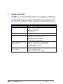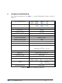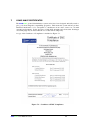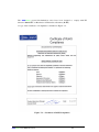
1
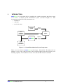
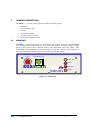
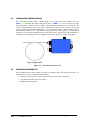
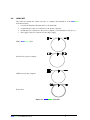
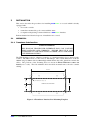
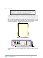
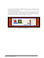
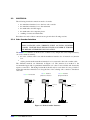
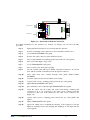
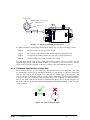
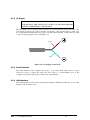
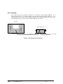
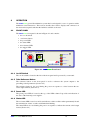
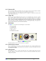
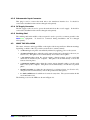
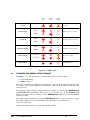
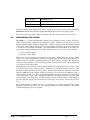
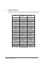
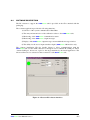
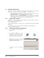
Seascan
User Manual
Model 102 & 202
SEA/07/5972 Issue 3
April 2007
seascan User Manual Issue 3
Seatronics Ltd
Geoscan House
Denmore Road
Aberdeen
AB23 8JW
Tel: +44 (0) 1224 853100
Fax: +44 (0) 1224 853101
seascan User Manual Issue 3
Systems Engineering & Assessment Ltd
Beckington Castle
PO Box 800
Frome BA11 6TB UK
Tel: +44 (0) 1373 852 000Fax: +44 (0) 1373
831 133
1
INTRODUCTION
3
2
GENERAL DESCRIPTION
4
2.1
MAIN UNIT
4
2.2
TRANSDUCER INTERFACE BOX
5
2.3
MOUNTING BRACKET KIT
5
2.4
CABLE KIT
6
INSTALLATION
7
3.1
MECHNICAL
7
3.1.1
Transducer Interface Box
7
3.1.2
Main Unit
8
3.2
ELECTRICAL
10
3.2.1
Echo Sounder Interface
10
3.2.2
Transducer interface box to Main Unit
12
3.2.3
DC Supply
13
3.2.4
Serial Interface
13
3.2.5
USB Interface
13
3.2.6
Earthing
14
3
4
OPERATION
15
4.1
FRONT PANEL
15
4.1.1
On-Off Switch
15
4.1.2
Power LED
15
4.1.3
Status LED
15
4.1.4
Reference LED
16
4.1.5
Trigger LED
16
4.2
REAR PANEL
16
4.2.1
Reference Button
15
4.2.2
RS232C Serial Connector
16
4.2.3
USB Connector
16
4.2.4
Echosounder Input Connector
17
4.2.5
DC Supply Connector
17
4.2.6
DC fuse
seascan User Manual Issue 3
Error! Bookmark not defined.
1
4.2.7
Earthing Stud
17
4.3
WHAT THE LEDS MEAN
17
4.4
CHANGING THE SERIAL OUTPUT FORMAT
18
4.5
REFERENCING THE SYSTEM
19
5
TROUBLE SHOOTING
20
6
TECHNICAL SPECIFICATION
21
7
COMPLIANCE CERTIFICATES
22
8
PATENT PROTECTION
24
seascan User Manual Issue 3
2
1
INTRODUCTION
seascan is a device which allows a standard echo sounder, navigation and plotter system
to be used as a complete ground discrimination system as shown in Figure 1-1. This
document provides the necessary information for:
• installation.
• operation.
• trouble shooting.
navigation
system
echo
sounder
electronics
latitude
longitude
depth
seascan
seascan
plotter
roughness
hardness
(depth)
echo
sounder
transducer
Figure 1-1 - Ground Discrimination System Components
There are two models in the seascan product range - 102 and 202. The 202 model can
interface to more echo sounders because it has a wider frequency range and a larger power
handling capability. The installation and use of the 102 and 202 models are identical.
seascan User Manual Issue 3
3
2
GENERAL DESCRIPTION
The seascan system package should contain the following items:
• main unit.
• remote interface unit.
• cable kit.
• mounting bracket kit.
• user guide (this document).
• PC Software Installation CD.
2.1
MAIN UNIT
The seascan main unit (Figure 2-1) is the heart of the system. It listens to the transmitted
echo sounder pulse in order to tune its own receiver and optimise its internal settings. It then
listens to the received echoes which it analyses into information about the seabed. This
information is then transmitted by the main unit to the plotter software. The main unit is
housed in a metal enclosure and is powered from the vessel's DC supply.
Take Reference
Power
Power OK
17mm
Status
seascan
3.66mm
SW1
Reference
Trigger
43mm
Figure 2-1 - Main Unit
seascan User Manual Issue 3
4
2.2
TRANSDUCER INTERFACE BOX
The Transducer Interface Box (TIB) (Figure 2-2) isolates the echo sounder from the
seascan main unit and ensures that the presence of seascan does not adversely affect
the performance of the host echo sounder. The transducer interface box is housed in a die
cast box and is installed close to the echo sounder itself. The enclosure is water resistant and
all cable entries are made through glands. A long umbilical cable to the main unit connects
the transducer interface box. This cable carries power and control signals to the transducer
interface box and carries transmitted pulse and received echo signals back to the main unit. A
white high voltage flying lead is also supplied connected to the echo sounder cable gland.
High voltage cable
Figure 2-2 - Transducer Interface Box
2.3
MOUNTING BRACKET KIT
The mounting bracket kit contains four slide-on brackets which allow the main unit to be
mounted in a variety of configurations including:
• attached to a horizontal or vertical surface such as chart table or desk area.
• suspended beneath a horizontal surface
• flush-mounted in a panel.
seascan User Manual Issue 3
5
2.4
CABLE KIT
The cable kit contains the cables necessary to complete the installation of the seascan
main unit, namely:
• a lead from Transducer Interface Box to the main unit;
• a serial interface cable for connection to the plotter computer;
• a USB cable for connection to the plotter computer (as an alternative to the above);
• a DC supply cable for connection to the ship's supply.
TIB to seascan cable
Serial lead to plotter computer
USB lead to plotter computer
Power lead
Figure 2-3 - seascan
seascan Cable Kit
seascan User Manual Issue 3
6
3
INSTALLATION
This section describes the procedures for installing seascan on a vessel which is already
equipped with:
• a host echo sounder.
• a transducer mounted in good contact with the water.
• a computer with plotting software which has a seascan interface.
Both mechanical and electrical aspects of installation are covered.
3.1
MECHNICAL
3.1.1 Transducer Interface Box
SAFETY WARNING
THE SEASCAN TRANSDUCER INTERFACE BOX CAN CONTAIN
HIGH VOLTAGES AND CURRENTS. ENSURE THAT IT IS NOT
CONNECTED TO THE HOST ECHO SOUNDER OR TO THE MAIN
UNIT WHEN MOUNTING.
The TIB should be bolted or otherwise secured to a convenient surface close to the host echo
sounder. The TIB consists of a die cast box with flanges. The overall dimensions of the are
160mm long by 90mm wide by 60mm high which include the cable glands but exclude the
cables. The positions of the mounting holes are shown in Error! Reference source not
found. (not to scale). The side with three holes should be mounted next to the echo sounder
cabling.
25mm
127.5mm
50mm
5mm diameter holes (5 off)
25mm
VIEWED FROM UNDERNEATH
Figure 3-1 Transducer Interface Box Mounting Template
seascan User Manual Issue 3
7
3.1.2 Main Unit
SAFETY WARNING
THE SEASCAN MAIN UNIT HAS SHARP EDGES.
WHEN
INSTALLING ON A DECKHEAD ENSURE THAT THERE IS NO
POSSIBILITY OF HEAD INJURY DURING NORMAL USE.
The main unit should be installed at a convenient place between the transducer interface box
and the plotter computer. Access to the front panel should be permanently available. Access
to the rear panel should be possible on an occasional basis. Using the brackets supplied, the
main unit can be mounted in a variety of configurations such as shown in Figure 3-2. To use
these brackets, take a screwdriver and gently undo the front panel (five screws). Slide it a
little to one side and two brackets can be slid onto either the upper or lower grooves in the
side of the casing (Figure 3-3). Slide the front panel the other way, and the other two brackets
can be slid onto the other side. Centre the front panel, and replace the five screws.
Figure 3-2 - Horizontal Mounting
Take Reference
Power
Power OK
17mm
Status
seascan
SW1
3.66mm
43mm
Reference
Trigger
Figure 3-3– Attaching the brackets
Deck head mounting is the same, but sliding the brackets into the upper channels; the other
way up.
seascan User Manual Issue 3
8
For either of these circumstances, the brackets can be moved to suit, or they can be at full
extension. In this case, the screws would be on a rectangle 130mm deep by 74mm wide. The
holes may be up to 5.5mm diameter.
To mount by the front panel, a rectangular cut-out must be made in a suitable panel, and the
Seascan unit slid in (much like a car radio), until its front panel is against the panel. The unit
should then be retained. This could be by small pieces of wood, screwed into the panel as
shown below. The cut-out should be 54mm by 170mm, or a little larger.
Take Reference
Power
Power OK
17mm
Status
seascan
SW1
3.66mm
43mm
Reference
Trigger
Figure 3-4 Panel Mounting
seascan User Manual Issue 3
9
3.2
ELECTRICAL
The following electrical connections need to be made:
• the transducer interface box to the host echo sounder.
• the transducer interface box to the main unit.
• the main unit to the DC supply.
• the main unit to the computer plotter.
• earthing of remote and main units.
Procedures for each of these connections are given in the following sections.
3.2.1 Echo Sounder Interface
SAFETY WARNING
HIGH VOLTAGES AND CURRENTS EXIST ON ECHO SOUNDER
CABLES. ENSURE THAT THE HOST ECHO SOUNDER IS TURNED
OFF BEFORE ATTEMPTING INSTALLATION.
The seascan interface to the host echo sounder is very simple and can be implemented by
one of two methods, namely,
• the echo sounder cable is cut and the transducer interface box is inserted as a junction
box.
• a flying lead from the transducer interface box is connected to the echo sounder cable.
The different methods are illustrated in Figure 3-5. The junction box method is the
recommended approach for permanent installation as it offers a more reliable and electrically
superior connection. The flying lead method should only be used where it is not possible to
mount the transducer interface box along the line of the existing echo sounder to transducer
cable run.
seascan installed
junction box method
seascan not installed
seascan installed
flying lead method
echo
sounder
cable
to main unit
to main unit
remote unit
remote unit
transducer
Figure 3-5 -Echo Sounder Interface
seascan User Manual Issue 3
10
To Echo-Sounder
1
1
4
To Transducer
6
Figure 3-6 - Junction Box Method Connections
For initial installation by the junction box method (see Figure 3-6) use the following
procedure
step 1
unplug transducer interface box from main unit if connected.
step 2
unscrew 4 retaining screws and remove lid of transducer interface box.
step 3
loosen ECHO SOUNDER cable gland.
step 4
unscrew the cable connectors (first and third screws).
step 5
remove ring terminal from earthing point between the two cable glands.
step 6
remove the white high voltage cable.
step 7
loosen TRANSDUCER cable gland.
step 8
remove nylon screw from gland opening.
step 9
cut echo sounder cable and expose 50mm of insulated conductors on both cut
ends, trim about 5mm of insulation from the signal conductors.
step 10
insert cable from echo sounder through cable gland marked ECHO
SOUNDER.
step 11
screw the cables into the first and third screw-clamps.
step 12
connect cable screen to earthing point between the two cable glands.
step 13
tighten ECHO SOUNDER cable gland
step 14
place transducer end of cable through TRANSDUCER cable gland.
step 15
screw the cables into the fourth and sixth screw-clamps, ensuring that
connection 3 & 4 are connected to the same colour conductor and that
connection 1 and 6 are both connected to the other colour conductor (see
Figure 3-6).
step 16
connect cable screen to earthing point between the two cable glands and
tighten.
step 17
tighten TRANSDUCER cable gland
step 18
replace lid, taking care to maintain the integrity of the waterproof seal and
tighten 4 retaining screws and ensuring that markings on lid align with the
correct glands.
seascan User Manual Issue 3
11
Signal wires
Cable between echo sounder
and transducer
Screen
White
Blue
1
1
4
6
Figure 3-7 - Flying Lead Method Connections
For initial installation by the flying lead method (Figure 3-7) use the following procedure
step 1
cut white cable to shortest possible length.
step 2
trim cable end exposing blue and white conductors and braid screen.
step 3
connect blue and white conductors to the echo sounder signal wires.
step 4
connect braid screen to echo sounder cable screen.
It is important that the high voltage cable run should be kept as short as possible. On the
supplied high voltage cable the black conductor is connected to the cable screen. Precise
details of the connection depends on the echo sounder cable and termination method.
3.2.2 Transducer Interface Box to Main Unit
The transducer interface box is connected by the umbilical cable to the main unit. The cable
is permanently connected at the transducer interface box end and has a connector at the main
unit end. The cable is 5m in length to accommodate the widest range of installations. The
cable should not be shortened. The 5m of cable allows installation of the transducer interface
box close to the echo sounder and the main unit close to the computer. If, after installation,
there is any slack cable then it should be bundled rather than coiled as shown in Figure 3-8.
Insert the connector in the socket marked TRANSDUCER INTERFACE BOX on the rear panel
of the main unit.
Figure 3-8 - Excess Cable Length
seascan User Manual Issue 3
12
3.2.3 DC Supply
SAFETY WARNING
ENSURE THAT THE VESSEL'S DC SUPPLY IS ISOLATED BEFORE
MAKING A PERMANENT CONNECTION.
The DC supply cable is supplied with a connector at one end and bare wires at the other. The
connections are brown for positive and blue for negative. The supplied cable is 1.5m long.
For a permanent installation this can be cut to suit the actual cable run. Connect the bare ends
to the vessel's DC supply as shown in Figure 3-9.
brown
blue
Figure 3-9 - DC Supply Connections
3.2.4 Serial Interface
The serial interface cable comprises two parts - a 3m cable itself with a 9 way D type
connector at each. Connect the other end of the cable to a serial interface port on the
computer as detailed in the plotter software user documentation.
3.2.5 USB Interface
The USB interface lead provides an alternative interface. Either the USB lead or the serial
interface lead should be used.
seascan User Manual Issue 3
13
3.2.6 Earthing
The main unit and the transducer interface box both have studs marked EARTH. It is
important that these are connected together with an earth strap that is then taken to a good
earthing point on the vessel. This earthing arrangement is shown in Figure 3-10. The end of
the earth strap can be tied to the echo sounder earth if it is grounded.
main unit
remote interface unit
to vessel earth
earth strap
Figure 3-10 - Earthing Arrangement
seascan User Manual Issue 3
14
4
OPERATION
The seascan ground discrimination system has been designed for ease of operation with a
minimum of user interaction. This section describes the controls, displays and connectors on
the front and rear panels and then the facilities available to the user.
4.1
FRONT PANEL
The seascan front panel is shown in Figure 4-1 and contains:
• the on-off switch.
• a reference button.
• the power LED.
• the status LED.
• the reference LED.
• the trigger LED.
Take Reference
Power
Power OK
17mm
Status
seascan
SW1
3.66mm
43mm
Reference
Trigger
Figure 4-1 - seascan
seascan Front Panel
4.1.1 On-Off Switch
The on-off switch is located at the left of the front panel and is protected by a surround.
4.1.2 Take Reference Button
The reference button on the front panel is used to reference the system outputs to the
prevailing seabed parameters (Section 4.5).
The reference button is also used during the power-on sequence to select between the two
serial output formats (Section 4.4).
4.1.3 Power LED
The green power LED is located at the top of the LED column. It provides an indication of
the state of the internal power supplies.
4.1.4 Status LED
The red status LED located second down indicates a fault condition when permanently lit and
the transmission of data over the serial link when flashing.
The status LED is also used during the power-on sequence to indicate the current serial output
format (Section 4.4).
seascan User Manual Issue 3
15
4.1.5 Reference LED
The red reference LED located third down on the right of the front panel indicates whether
the system output is referenced to known seabed parameters (Section 4.5).
The reference LED is also used during the power-on sequence to indicate the current serial
output format (Section 4.4).
4.1.6 Trigger LED
The front panel trigger LED indicates the presence of a transmitted pulse on the echo sounder
input. If the system consistently fails to find a pulse, for instance when the echo sounder is
turned off or the frequency is changed, the system will automatically enter a re-acquisition
mode. If pulses are being transmitted then the system can take up to 10 seconds to find the
pulse and re-tune the system, depending on the echo sounder depth setting. If no pulses are
being transmitted then the system will wait indefinitely.
4.2
REAR PANEL
The seascan rear panel is shown in Figure 4-2 and contains:
• DC power input
• an earthing stud
• RS232 connector
• USB connector
• the interface to the TIB.
17mm
3.66mm
SW1
Power
10-36 Vdc
43mm
O/P - RS232
Earth
O/P - USB
Echosounder
input
Figure 4-2 - seascan
seascan Rear Panel
In normal operation, access to the rear panel is not required.
4.2.1 RS232C Serial Connector
The 9 way RS232C port is used to connect the main unit to the computer which runs the
plotter program. Either it or the USB connector should be connected at installation time and
not changed subsequently.
4.2.2 USB Connector
The USB port is used to connect the main unit to the computer which runs the plotter
program. Either it or the Serial connector should be connected at installation time and not
changed subsequently.
seascan User Manual Issue 3
16
4.2.3 Echosounder Input Connector
This plug is used to connect the main unit to the transducer interface box. It should be
connected at installation time and not changed subsequently.
4.2.4 DC Supply Connector
The DC supply socket is used to power the main unit from the vessel's supply. It should be
connected at installation time and not changed subsequently.
4.2.5 Earthing Stud
The earthing stud in the middle of the rear panel is used to provide a common ground for the
seascan equipment. It should be connected during installation and not changed
subsequently.
4.3
WHAT THE LEDs MEAN
The status, reference and trigger LEDs on the right of the front panel have different meanings
depending on which of the six possible system modes is current, namely,
• a self test diagnostic phase automatically initiated by applying power to the system.
• a format selection phase when the serial output format can be changed by the user (see
Section 4.4). This phase follows immediately on from the self test phase.
• a test pattern phase when the system outputs a known pattern over the serial link
which can be checked by the computer. This phase follows immediately on from the
format selection phase.
• a parameter transfer phase when the system outputs internal settings over the serial
link for use by the computer. This phase follows immediately on from the test pattern
phase.
• normal operation, in either the un-referenced or referenced state (see Section 4.5).
This phase follows immediately on from the parameter transfer phase.
• the fault condition mode which can be entered at any time. The system remains in this
mode until turned off.
The flashing codes for the LEDs are shown in Figure 4-3.
seascan User Manual Issue 3
17
status
(red)
reference
(red)
trigger
(orange)
flash once
self test
basic
5 flashes, once a second
format selection
NMEA
basic
16 flashes, twice a second
test pattern
NMEA
basic
16 flashes, twice a second
parameter transfer
NMEA
un-referenced
flash once per ping
normal operation
referenced
permanently on
fault condition
Figure 4-3 - LED Codes
4.4
CHANGING THE SERIAL OUTPUT FORMAT
The seascan serial output can be produced in one of two formats, namely,
• basic ASCII string.
• NMEA sentence.
The choice of format is determined by which plotter is being used and this information should
be available in the plotter supplier's documentation. The system is delivered with the basic
format selected.
The currently selected message output format are checked by observing the REFERENCE
and STATUS LEDs immediately after power-on (see Section 4.3). If the STATUS LED
flashes then basic format is selected. If the REFERENCE LED flashes then the NMEA
format is selected.
The output format is changed by using the REFERENCE button on the front panel to toggle
the settings within four seconds immediately after the unit power is switched on:
1) Power on the Unit
2) Press the reference button to toggle through three settings
seascan User Manual Issue 3
18
Basic Format
REFERECE is lit
NMEA Format
STATUS is lit
Stored setting
REFERENCE and STATUS are lit.
After four flashes of the LEDs, data will be output in the selected format. The STATUS or
REFERENCE indicator will flash rapidly indicating diagnostic messages being output.
The selected message output format is remembered by the system when it is powered off.
4.5
REFERENCING THE SYSTEM
The seascan system automatically compensates for changes in echo sounder frequency,
power level and pulse length and for changes in depth. Therefore as long as the sea bed
remains unchanged the roughness and hardness outputs from the system will remain centred
on the same values. There will always be a small amount of variation about these values due
to system noise and natural variability. The actual numerical values which are produced are
governed by scaling within the system. This scaling can be set to one of two states, namely,
• factory default settings.
• known ground settings.
The system can be operated successfully in both states. When using the factory default
settings, it is called un-referenced operation and when using the known ground settings it is
called referenced operation. In either referenced or un-referenced operation, the outputs are
consistent and repeatable so that if the same ground is revisited the system outputs will return
to be centred on the same values.
The difference between the two states is that in referenced operation the user has some control
over the absolute values produced. This is achieved by pressing the reference button on the
front panel when traversing known ground. Pressing the button will light the front panel
reference LED and set the outputs for this sea bed type to be centred on a roughness value of
1 and a hardness value of 1. It is recommended that the system is referenced to a mid range
sea bed type such as sand. This scaling will remain in force until the button is pressed again
when it reverts to un-referenced operation using the factory default settings. If the button is
pressed again the system will be referenced to the latest sea bed type and not the previous
one.
The system remembers which state it is in (referenced or un-referenced) and the scaling
parameters when it is powered off. The scaling parameters are made available to the plotter
software during the power-on sequence.
seascan User Manual Issue 3
19
5
TROUBLE SHOOTING
The seascan ground discrimination system has been designed for reliability and
continuous trouble free operation. There is no need for routine maintenance. This section
gives initial guidelines for trouble shooting basic faults which can occur from time to time,
especially when the installation is disturbed. If the suggested simple remedies do not work,
the user should not open the unit and attempt repair himself but should contact his distributor.
Fault
action
power LEDs off
check on off switch
check vessel's DC supply
check DC supply lead
check DC fuse
status LED permanently on
turn off, turn on and if fault reoccurs contact distributor
trigger LED not flashing
check that echo sounder is transmitting
check that echo sounder is receiving
check echo sounder connection
check umbilical cable is connected
if all okay then contact distributor
trigger LED flashing but status check echo sounder power level within limits
LED not flashing
check echo sounder frequency within limits
check echo depth within limits
contact distributor
status LED flashing but plotter check serial or USB cable connection
not responding
check serial output format
contact distributor or plotter supplier
seascan User Manual Issue 3
20
6
TECHNICAL SPECIFICATION
The technical specification for the seascan ground discrimination systems is given in
Table 6.1.
echo sounder frequency
maximum echo sounder power
28kHz to 100kHz
20kHz to 200kHz
seascan 102
seascan 202
4kW
10kW
seascan 102
seascan 202
transducer impedance
50Ω to 200Ω
insertion loss
<0.5dB
frequency selection
automatic
power level compensation
automatic
pulse length compensation
automatic
power level referencing
manual, one time
minimum operating depth
10m
maximum operating depth
set by host echo sounder and bottom type
update rate
tracks host echo sounder PRF
RS232C serial interface settings
4800 baud, 8 data bits, 1 stop bit
or
38400 baud, 8 data bits, 1 stop bit
output format
basic ASCII string or NMEA-0183 sentence
diagnostics
built in self test at power on
DC supply voltage
10V to 36V
power consumption
3W
dimensions
228mm × 190mm × 56mm
160mm × 90mm × 60mm
Main unit
Transducer Interface
weight
1.1 kg
0.9kg
main unit
remote interface unit
operating temperature
0°C to 40°C
Table 6.1 - seascan
seascan Technical Specification
seascan User Manual Issue 3
21
7
COMPLIANCE CERTIFICATES
The seascan ground discrimination system series have been designed and fully tested to
give good electromagnetic compatibility properties. This means the system will not produce
unwanted interference or be susceptible to interference from other sources in a normal
operating environment. In the presence of high field strengths and electrostatic discharges
occasional pings may be missed but the loss of data will be temporary.
A copy of the Certificate of Compliance is included as Figure 7-1.
Figure 7-1 – Certificate of EMC Compliance
seascan User Manual Issue 3
22
The seascan ground discrimination series have been designed to comply with EU
directive 2002/95/EC on Restriction of Hazardous substances (RoHS).
A copy of the Certificate of Compliance is included as Figure 7-2.
Figure 7-2 – Certificate of RoHS Compliance
seascan User Manual Issue 3
23
8
PATENT PROTECTION
The seascan ground discrimination systems are based on patented techniques and enjoy
protection in a number of countries worldwide. The relevant patents are given in Table 8.1.
country
application
number
serial
number
United Kingdom
8221670
2102573
United States
572055
4648081
Canada
445335
1231168
France
85302020.4
0156636
United Kingdom
85302020.4
0156636
Australia
40193/85
586623
Canada
477145
1253612
India
216/MAS/85
164623
Norway
851118
166347
Spain
541508
541508/X
United States
715017
4777630
Europe
90112342.2
0397221
France
90112342.2
0397221
The Netherlands
90112342.2
0397221
United Kingdom
90112342.2
0397221
Australia
42821/89
626921
Norway
90.3831
180763
Europe
92301560.6
0501743
France
92301560.6
0501743
United Kingdom
92301560.6
0501743
United Kingdom
9927462.3
pending
Table 8.1 - Patents
seascan User Manual Issue 3
24
ANNEX A
PC SOFTWARE INSTALLATION AND SET-UP
seascan User Manual Issue 1
Error! Reference source not found.
A.1
SOFTWARE DESCRIPTION
The PC software to support the seascan unit is provided on the CD contained with the
packaging.
The software application provides the following functions:
1) Selection of the system communications Baud Rate
2) The entry and transmission of the calibration values to the seascan unit.
3) Monitoring of the seascan communication status
4) Monitoring of the seascan output messages
5) Display of the seascan output message stream within the message window
6) The ability for the user to input transducer depth (seascan 202 models only)
The software installation CD also installs drivers to allow communications with the
seascan unit over the USB connection as though it were a standard PC COM port. These
‘virtual COM port’ drivers are copied to the target machine by the install application. The
drivers will need to be activated on first connection of the seascan unit.
Figure A-1 Seascan PC software interface
seascan User Manual Issue 3
A-1
A.2
SOFTWARE INSTALLATION
Installation of the software application is carried out using a Windows software installer
application from the CD provided. To install the seascan follow these steps.
A.2.1
•
When following the Installation procedures, ensure that the Seascan unit is
DISCONNECTED to the host PC with the USB or the serial cable.
•
Ensure the subject PC is DISCONNECTED from any Internet access. (Pull the
Ethernet plug until this entire procedure is complete). This will prevent Windows
from attempting to access the internet to look for the Seascan drivers.
Installing .NET Framework
The seascan software application requires installation of extension libraries to Windows.
These are included on the Installation CD.
1) Insert the Installation CD
2) From ‘Windows Explorer’ open the directory on the Installation CD called ‘MS .NET
Framework’.
3) Double Click on the ‘dotnetfx’ to unpack and install Microsoft .NET Framework
4) Follow the instructions presented.
A.2.2
Installing the Seabed Profiling Application
1
Insert the seascan CD into the PC
CD driver
2
Use “Windows Explorer” or “My
Computer” to select the CD drive letter
and display the file contents of the CD.
The CD will contain the following files.
3
Double click on setup to run the
installation application. This following
installation window will appear.
Click Next to continue the installation
procedure
seascan User Manual Issue 3
A-2
4
Select the required installation folder.
It is recommended that the default folder
(shown in the folder box) is used,
otherwise, the user may choose to input
an alternative folder name..
Click Next to continue the installation
procedure
5
The software will install to the chosen
location.
On completion, Click Next to continue
the finish procedure
6
The Installation Complete window will
be displayed.
To complete the installation procedure,
press Close
7
The installation procedure will produce
the Seascan Seabed Profiling icon on the
desktop.. An entry for Seascan will be
created in the programmes menu
(start/programmes/Seascan) that will
contain the both a shortcut to
seascan software application and the
user manual.
Installation is now completed
seascan User Manual Issue 3
A-3
A.2.3
Uninstalling the Seascan Seabed Profiling Application
Un-installing any existing Seabed profiler application from the host PC may be carried out in two
ways
a. By re-running the installer from the original disk and selecting ‘remove’
b. From Control Panel/Add Remove Programmes,
i. Select Seascan102 (or Seascan 202)
ii.
A.2.4
Click Remove.
Connecting Seascan for the first time over USB
1. After installation of the software to the host PC, power up the seascan.
2. Insert the USB cable in the PC, and the other end in the seascan.
3
After a short delay note the pop-up
window:
4
This is followed by the ‘Wizard:’we start installation for the
SEASCAN Device Serial Port
converter
Click Next to Continue
seascan User Manual Issue 3
A-4
5
The Install Hardware device drivers
menu will be displayed.
Select the Option to search a
suitable drive for my device
Click Next to continue
6
On the Locate Driver Files window
Select the option to Specify a
Location
Click Next to Continue
7
When this menu appears, select
browse
Use the menu
following folder
to
select
the
C:\Seascan Drivers
Click OK to Continue
8
The Driver File search results
window and will automatically
install the necessary driver for the
Seascan unit.
Click Next to Continue
seascan User Manual Issue 3
A-5
9
The driver will install and the
following
window
will
be
displayed.
Click FINISH
10
A second driver will then install
and the following window will
appear. This driver is the USB
Serial Port driver
Click Next to continue
11
Repeating the process, select the
specify a location option.
Click Next to continue
seascan User Manual Issue 3
A-6
12
Click Browse
Use the menu
following folder
to
select
the
C:\Seascan Drivers
Click OK to Continue
13
The Driver File search results
window and will automatically
install the necessary driver for the
Seascan unit.
Click Next to Continue
14
The driver will install and the
following
window
will
be
displayed.
Click FINISH
15
You may be requested to restart the
PC after the installation
Click Yes.
seascan User Manual Issue 3
A-7
A.3
CHECKING THE COM PORT CONFIGURATION
The virtual COM port allocated to the seascan when using the USB connection may vary
and is dependant on the particular configuration of the host PC.
The actual COM port may be checked through the windows setting by following these
instructions.
1
Ensure that the Seacsan unit is
connected to the PC using the USB
connection
2
Navigate to Windows Control Panel
<Start/Settings/Control Panel >
3
Select System to bring up the system
menu and select the hardware tab
4
Click on the Device Manager to obtain a
window displaying the hardware tree.
5
Expand the items ‘ports (COM & LPT)’
and note an additional entry with a
descriptor such as “USB Serial Port
(COM8).
6
DETACH
the
USBSeascan
Connection and note that the entry
seascan User Manual Issue 3
A-8
described above is removed from the
hardware tree.
Reinstate the connection and note the
reverse.
7
A.4
Note the COM port number. This is the
virtual COM port number used withing
the Seascan Seabed profiling application
for connection of the unit over USB.
USING THE SEABED PROFILING APPLICATION
Each time the seascan unit is turned on, or connected over the USB, the virtual COM port
driver is automatically loaded. This occurs during the seascan initiation sequence. To ensure
that the application connects to the newly loaded driver, follow these instructions.
Run the seascan Seabed Profiling Application from the desktop or programme menu
1) Initialise the seascan so it is in normal operation.
2) After a short delay the driver will load.
3) The appropriate COM port may be selected by clicking off the COM setting in the right
hand side of the application window and clicking back on it again.
4) This procedure should be followed each time that the seascan is restarted.
seascan User Manual Issue 3
A-9
A.5
SELECTING THE BAUD RATE
As supplied, the seascan unit will communicate at 4800 baud, the older NMEA standard.
From the year 2000, a higher standard of 38,400 baud has been adopted. This will normally
be configured by the dealer on request.
If it is wanted to use this speed, then it is necessary to remove both front and back panels, and
unclip all connectors. Slide the PCB out, and onto an anti-static surface. Locate link P17.
Place the supplied link so that it shorts the two pins together.
Slide the PCB most of the way back in again. Reconnect the exposed connectors in the same
places as detached from. This should be easily achieved without straining the cables.
From the other side, pull the PCB out a little, and attach the connectors from the other panel.
Screw the rear panel and plastic bezel back into place; then do the same with the front panel.
Note that the PC’s software will also need to be set to the correct baud rate on next use.
Link at P17 shorting = 38,400 baud. Link not shorting = 4800 baud
seascan User Manual Issue 3
A-10