1
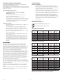
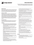
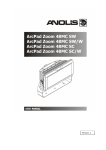
Manufactured by Day4 Energy Inc.
#401, 4621 Canada Way, Burnaby, BC Canada V5G 4X8
office:
1 604 297 0444
fax:
1 604 297 0445
email: [email protected]
web: www.day4energy.com
INSTALLATION MANUAL
This manual applies to the following products: Day4 Energy 36MC, 48MC, 48MC-S and 60MC-I.
Please read and study this manual completely before installation or use of any Day4 Energy Inc. (Day4 Energy) photovoltaic modules.
Refers to instructions for
Europe installations only
Refers to instructions for
USA and Canada installations only
Refers to instructions for
36MC, 48MC & 48MC-S modules only
INTRODUCTION
• To avoid the danger of electric shock, fire and injury, do not
disassemble the Day4 Energy module, or remove any part
installed by Day4 Energy or any authorized dealer or integrator.
With proper installation, operation and maintenance, Day4 Energy modules
will provide you with clean, renewable solar electricity for many years.
This manual contains important installation, maintenance and safety
information. Retain this manual for future reference. The word “module(s)”
as used in this manual refers to one or more Day4 Energy 36MC, 48MC,
48MC-S and 60MC-I photovoltaic modules.
• Unauthorized persons should not open the cover of the junction
box as this increases chances of dangerous electric shock, may
cause damage to the module and will void the warranty. Only a
qualified licensed professional should attempt to open the cover
of the junction box.
Disclaimer of Liability
• To avoid the risk of electric shock or injury, employ suitable
clothing and tools to prevent direct contact with solar electric
systems with voltage greater than 40V.
Day4 Energy does not assume responsibility and expressly disclaims
liability for loss, damage or expense arising out of or in any way connected
with installation, operation, use or maintenance by using this manual.
Day4 Energy assumes no responsibility for any infringement of patents or
other rights of third parties which may result from the use of Day4 Energy
modules. No license is granted by implication or under any patent or patent
rights. The information in this manual is believed to be reliable, but does
not constitute an expressed and/or implied warranty. Day4 Energy reserves
the right to make changes to the product, specifications or manual without
prior notice and on its sole discretion.
• Use caution when carrying Day4 Energy modules. It is
recommended that two or more persons carry the module by its
frame and use non-slip gloves.
• Do not carry a Day4 Energy module by its connecting wires or
junction box.
• Do not drop anything on the surface of a Day4 Energy module. A
damaged surface can cause electric shock and injury.
• To avoid the hazard of electric shock and fire, be sure that all
system components are compatible with Day4 Energy modules.
Components should not subject the module to mechanical or
electrical hazards.
General Information
The installation of photovoltaic Day4 Energy modules requires a great
degree of skill and should only be performed by qualified licensed
professionals, including, without limitation, licensed contractors and
licensed electricians.
• Since sparks may occur, do not install the Day4 Energy module
where flammable gases or vapors are present.
• Never leave a Day4 Energy module unsupported or unsecured,
especially on elevated places of installation like roofs, buildings
and on scaffoldings.
WARNING
• All instructions should be read and understood before attempting
to install, wire, operate or maintain the photovoltaic Day4 Energy
module. Contact with electrically active parts of the module such
as terminals can result in burns, sparks and lethal shock whether
the module is connected or disconnected.
• Do not drop a Day4 Energy module.
• Do not use or install a broken or damaged Day4 Energy module.
• Day4 modules with damaged back-sheets should never be
installed or operated.
• To avoid the risk of fire or damage, do not artificially concentrate
sunlight on a Day4 Energy module.
• Some transformer-less inverters are not suitable for use with
photovoltaic modules in specific applications. Check with the
inverter manufacturer, the inverter installation manual and attain
the inverter manufacturer’s approval prior to use.
• Do not touch the junction box terminals. This can cause electric
shock and injury.
• The installer assumes the risk of any injury that might occur
during installation, including, without limitation, the risk of
electric shock and or fire.
• Do not change the wiring of bypass diodes.
• Do not install Day4 Energy modules above flammable material.
Special attention needs to be paid when Day4 Energy modules
are installed as building integrated product (BIPV).
• Day4 Energy modules generate DC electrical energy when
exposed to sunlight or simulated sunlight sources. Although a
single module produces only a low voltage and current, shocks
and burns are still a potential risk.
• Do not remove the frame or parts thereof.
• Do not run reverse current through a Day4 Energy module in an
attempt to de-ice the module or for any other purpose.
• To avoid the danger of electric shock and injury, cover the front
glass surface of the Day4 Energy module with a dense, opaque
material during installation and handling.
• Do not stand or walk on the surface of a Day4 Energy module as
you may cause damage to the frame or other parts of the module.
• The shock hazard increases as Day4 Energy modules are
connected in parallel producing higher current. The shock risk
increases as modules are connected in series producing higher
voltages.
CAUTION
• Use a Day4 Energy module for its intended purpose only. (Please
refer to the Day4 Energy 36MC, 48MC, 48MC-S and 60MC-I series
warranty document.)
• To avoid the peril of electric shock, work only under dry conditions
with dry modules and tools.
• To avoid reduced module functionality, damage, inoperable
conditions and other unknown troubles, do not treat the
backsheet or front surface with paint or adhesives.
• To avoid the risk of injury and damage to the module, do not
stand or step on a Day4 Energy module.
• Do not disconnect connectors under load.
• To avoid the threat of electric shock and/or fire, do not puncture
or damage the backsheet of a Day4 Energy module. To avoid
the peril of electric shock and injury, children and unauthorized
persons should not be allowed near the installation of modules.
• In Europe grounding is recommended for Day4 Energy modules.
• In USA and Canada it is a requirement to completely ground all
Day4 Energy modules.
101310-A4-EN
Refers to instructions for
60MC-I module only
1
GENERAL SAFETY
INSTALLATION
General
Follow all permission, installation and inspection requirements.
• Please read this guide completely before installation or use of
Day4 Energy modules. This section contains electrical and
mechanical specifications needed before using your modules.
• Before installing Day4 Energy modules, contact the appropriate
authorities to determine permissions, installation and inspection
requirements to be followed.
• Day4 Energy modules should be firmly fixed in place in a
manner suitable to withstand all expected loads, including
wind and snow loads.
• Electrically ground Day4 Energy modules for all systems of any
voltage (mandatory in USA and Canada, recommended in Europe).
If not otherwise specified it is recommended that requirements
of the latest National Electrical Code (USA) or Canadian Electric
Code (Canada) or any other applicable national or international
electrical standards be used.
• Do not drill additional mounting holes into module frames,
as this will void the warranty.
• Day4 Energy modules must not be fitted as overhead or vertical
glazing.
• Be sure that the construction or structure (roof, facade, etc.)
where the Day4 Energy modules are being installed has enough
strength to support the added module and structure weight. For
modules that are to be mounted on roofs, special construction
or structures may be required for proper installation. Both roof
construction and module installation design have an effect on the
fire resistance of a building. Improper installation may contribute
to fire hazards. Additional devices such as ground fault, fuses and
disconnects may be required.
• Day4 Energy modules must be installed in a way that ensures the
junction box is in the uppermost position.
• The appropriate material should be used for mounting hardware
to prevent the module frame, mounting structure and hardware
itself from corrosion.
• Install Day4 Energy modules where they are not shaded by
obstacles like buildings and trees. Pay attention to avoid partial
shading by objects during the daytime.
• Do not use Day4 Energy modules of different specifications
(power class, size, etc.) in the same system.
• Do not operate the module if it is shadowed or otherwise covered
in its entirety or partially by debris, leaves, tree branches, dirt,
bird droppings, snow, ice and/or any other substance or objects
capable of preventing the light from illuminating the front
surface of the module in a uniform unobstructed manner (refer to
section in this manual labeled “Notes on Installation”).
• Follow all safety precautions of other system components used.
• Do not change or alter Day4 Energy modules or apply improper
means, such as, but not limited to, mirrors and/or other optical
systems of any kind. Do not operate the modules under artificially
concentrated sunlight such as an optical system and/or in direct
contact with solar thermal systems.
• Do not permanently operate the module if it is shadowed or
otherwise covered in its entirety or partially by debris, leaves,
tree branches, dirt, bird droppings, snow, ice and/or any other
substance or objects capable of preventing the light from
illuminating the front surface of the module in a uniform
unobstructed manner (refer to section in this manual labeled
“Notes on Installation”).
UL Listing Information
(applies to USA and Canada only):
To satisfy UL requirements when installing Day4 Energy modules be sure to:
1. Use only stranded single-conductor wire of listed type USE-2,
12 AWG, rated 90°C, 600 V, sunlight resistant for Day4 Energy
modules and interconnect wiring that is exposed to weather.
• Please contact your Day4 Energy authorized representative with
questions regarding mounting profiles for modules.
2.Observe the requirements described in sections of this manual
labeled “Installation” and “Specifications”.
Notes on Installation
• Clearance between the Day4 Energy module frame and the
mounting surface is required to allow cooling air to circulate
around the back of the module. This also allows any condensation
or moisture to dissipate. The module should never be sealed to
the mounting surface with sealant preventing air from circulating
under the module.
3.Grounding of the Day4 Energy module frame is required. When
ground wires greater than 6 mmC (No. 10 AWG) are required the
installer will need to provide suitable terminal connectors.
IEC 61730 Application Class A Information
In Europe only:
The recommended distance is minimum 50 mm.
(applies to Europe only)
Day4 Energy modules are designed to pass the criteria of application class A
requirements according to IEC 61730-part 1.
In USA and Canada only: In order to maintain UL Listing, a
minimum clearance of 10.16 cm (4 in) is required between
module and any installation surface. A minimum slope
of 5 inch/ft for installations over a roof is required to
maintain the fire class ratings.
To satisfy IEC 61730 requirements when installing the Day4 Energy modules
be sure to:
1. Use only double insulated stranded copper type cable. The cable
should be resistant to UV, water, ozone, fluids, salt, general weathering and abrasion. The cable should be halogen free and flame
retardant for the Day4 Energy module and interconnect wiring. Be
sure the cable is certified according to IEC 60228 class 5.
• In order to determine the maximum annual yield, the optimum
orientation and tilt of the Day4 Energy modules must be
identified. Sunlight shining vertically onto the modules will
give the best conditions to generate maximum power. To avoid
performance drops in series circuits, ensure all modules have the
same orientation and tilt. Modules should be of the same power
class.
2.Observe the requirements described in sections of this manual
labeled “Installation” and “Specifications”.
3.Equipotential bonding of the Day4 Energy modules and module
frame is recommended. The equipotential bonds between
modules may only be connected and approved by a qualified
electrician.
• Even the slightest partial shading, like from dirt deposits, will
cause a reduction in yield. A module is considered “shadow-free” if
it is un-obscured across its entire surface for the entire year. Even
on the shortest day of the year, un-obstructed sunlight should
reach the module.
• Option 1: Connect the module frame using cables [16 mmC (0.64
inC)] with cable lugs. Use the holes [diameter 4 mm (0.16 in)]
for this purpose. To create the conductive connection (frame is
anodized), use a self-tapping screw [diameter 5 mm (0.20 in)] or a
serrated washer.
• The recommended standoff height minimum to satisfy the UL
fire class C rating is 10.16 cm (4 in). Other mounting methods will
affect the fire class rating. The fire class rating of the PV module
installation must meet the code requirements as well as the
requirements of the specific place of installation.
• Option 2: Create an electrical connection between the frames and
the mounting system by using serrated lock nuts
(see “Installation”, Figure 1 – Example B).
• Please refer to Figure 1 and Figure 2 for proper installation.
4.Do not apply any external voltage higher than Voc labeled on the
module.
5.Refer to the module label for maximum series fuse rating.
101310-A4-EN
2
DIODES
Earth Ground Wiring
Ground should be carried out by securing the Day4 Energy module or
array frame to avoid the hazards of electric shock or fire. The array frame
should be grounded in accordance with NEC Article 250 (USA). Installations
in Canada shall be in accordance with CSA C22.1, Safety Standard for
Electrical Installations, CEC part 1. Contact local authorities to determine the
necessary grounding code requirements.
Bypass Diodes
Day4 Energy modules in series strings that are partially shaded may cause
reverse voltage across cells or modules because current from other cells in
the same series is forced to flow through the shaded area. This may cause
undesirable heating to occur. The use of a diode to bypass the shaded area
can minimize both heating and reduce the array current.
Proper grounding is achieved
by connecting the module
frames and structural members
contiguously together using a
suitable “grounding conductor.” It is
recommended to utilize a UL listed
grounding lug made of stainless
steel. Use a tin-plated or beryllium
grounding lug if the grounding
method involves attachment of
a grounding lead to the module
frame.
All Day4 Energy modules are equipped with factory installed bypass
diodes. The factory installed diodes provide proper circuit protection
for the systems within the specified system voltage so that no other
additional bypass diodes are required. Contact your authorized Day4 Energy
representative for the proper diode type if it is necessary to add or change
diodes due to system specifications.
WIRING
General
All wiring methods should be in accordance with the NEC in USA or CEC in
Canada or any other code, electrical code, law or bylaw applicable for the
place of installation.
MODULE FRAME
1
2
3
4
The grounding conductor,
grounding lead, or strap may be
Ilsco Model GBL-4DB
copper, copper alloy, or another
Ground Lug
material acceptable for use as an
electrical conductor per NEC/CEC.
1 6-32 stainless steel nut
The grounding conductor must
2 #6 stainless steel star washer
make a connection to earth using
3 #6 stainless steel washer
a suitable earth ground electrode.
4 6-32 stainless steel screw
Ensure positive electrical contact
through the anodizing on the
module’s frame by utilizing one of the following grounding methods:
• All wiring should be completed by a qualified licensed
professional.
• Wiring should be protected to help ensure personal safety and to
prevent damage.
• All Day4 Energy modules connected in series should be of the
same model class and/or type.
• Do not connect Day4 Energy modules in parallel without using a
connection box.
• Cable used for any wiring should be sized according to applicable
electrical codes.
Attach the grounding conductor:
1. To one of the 4 mm (0.16 in) holes marked ‘ground’ with a nut,
bolt or screw assembly and a serrated washer, external toothed
washer, or a paint piercing washer for attachment of the
grounding lug to the Day4 Energy module frame.
• Any cable used in the installation should conform to the
requirements of IEC 60228 class 5 (Europe only).
Day4 Energy Module Wiring
2.To electrically conductive metal, such as that of a support
structure which has been bonded to the module frame through
a bonding or external tooth washer, or a welded, or a soldered for
brazed joint or other suitable means as described above.
• The maximum number of Day4 Energy modules that can be wired
in series or parallel design is dependent on legal requirements,
maximum current and voltage ratings as indicated on the module
label, installation design, space and further specifications of
additional equipment such as inverters and converters.
3.With two or more screws or two full threads of a single screw
engaging the module frame metal.
• Day4 Energy modules must have the same amperage when
connected in series. When connected in parallel, the modules
must have the same voltage. The modules must not be connected
together to create a voltage higher than the permitted system
voltage according to protection class A.
Attention: Do not allow dissimilar metals such as copper and aluminum
to come in contact with each other. Use grounding lugs made of stainless
steel, beryllium or tin-plated. Never use self-tapping screws to connect the
grounding conductor.
• The Day4 Energy modules can be used for off-grid installations,
like charging batteries, if electronic equipment such as a power
tracker is used to control module output parameters and provides
accurate electrical output according to off-grid appliance
specifications.
Day4 Energy Module Terminations
A junction box as a terminal enclosure is equipped for electrical connections
on Day4 Energy modules. Day4 Energy modules are equipped with industry
proven interconnection systems in either UL or IEC compliant versions,
output cables, and male and female cable couplers. Use the couplers for
electrical connections only.
• Please contact your local licensed installer regarding the use of
Day4 Energy modules in off-grid applications and in combination
with charge controllers or similar equipment.
Please refer to module data sheet and contact your Day4 Energy authorized
representative with questions regarding electrical connections for Day4
Energy modules.
• Day4 Energy modules contain factory installed bypass diodes. If
these modules are incorrectly connected to each other the bypass
diodes, cables or junction boxes may be damaged.
Junction Box and Terminals
Day4 Energy modules are equipped with one junction box with terminals
for both positive and negative polarity and bypass diodes.
Array Wiring
The term “array” is used to describe the assembly of several Day4 Energy
modules on a support structure with associated wiring. Use insulated
copper wire that is suitable for outdoor use and is insulated to withstand
the maximum possible system open circuit voltage. Check local codes for
further requirements.
One terminal is dedicated to each polarity with the polarity symbols
engraved onto the terminals or junction box.
No modifications to the junction box are permitted.
Conduit
For applications where wire conduits are used, follow the applicable codes
for outdoor installation of wires in conduits. Verify that all fittings are
properly installed to protect wires against damage and prevent moisture
intrusion.
101310-A4-EN
3
STANDARD OPERATING CONDITIONS
SPECIFICATIONS
Notes on Specification
It is recommended that Day4 Energy modules be operated under
“Standard Operating Conditions” (SOC).
• Rated electrical characteristics are within 3.5% of the values
measured at Standard Test Conditions (STC). STC are: Irradiance
of 1000 W/mC, 25°C cell temperature and solar spectral irradiance
per IEC 60904-3 (AM1.5 solar spectral irradiance).
An installation location with conditions different from SOC or with other
“Special Conditions” (see below) should be avoided. SOC of Day4 Energy
modules are as follows:
• The current output for the Day4 Energy modules is shown in the
Specifications as measured at Standard Test Conditions. These
conditions may not be frequently observed in actual practice.
1.) Standard Operating Conditions
• The Day4 Energy module should be operated only in
terrestrial applications. No space or other “Special
Conditions” (see below).
• Under normal conditions a Day4 Energy module may experience
conditions that produce more current and/or voltage than
reported at Standard Test Conditions. Accordingly, the values of
Isc and Voc marked on listed module should be multiplied by a
safety factor of 1.25 when determining voltage ratings, conductor
capacities, fuse sizes, and size of controls connected to the
module output.
• The operating temperature of the module should be
within -35°C (-31°F) to 90°C (194°F).
• The relative humidity should be within 45% to 85%.
• Installations have to be carefully reviewed in regards to wind
loads. Appropriate installation methods must be used. If wind
loads higher than 2400N/mC are expected, contact Day4
Energy for further information.
Electrical ratings at STC:
Maximum system voltage rating:
2.) Special Conditions
Europe: IEC 61215/IEC61730 rating = 1000V
• Operating temperature and installation place conditions are
different from SOC.
USA and Canada: UL 1703 rating = 600V
• The salt damage is extreme at the installation location.
• The local climate generates snow accumulations heavier
than 2400N/mC for extended periods of time which are not
regularly removed by authorized personnel.
Day4 36MC Series Modules
Pmax
Maximum
Maximum
Short Circuit
(Umpp*Impp) Power Voltage Power Current
Current
(W)
(V)
(A)
(A)
115
16.80
6.89
7.60
120
16.95
7.08
7.70
125
17.21
7.30
7.90
130
17.55
7.46
8.05
135
17.78
7.60
8.10
140
17.98
7.79
8.20
145
18.24
7.95
8.30
• The local climate generates hail storms with hailstones larger
than 20 mm in diameter.
• The local climate generates sand and dust storms on more
than three days/year.
• The air pollution, chemically active vapors, acid rain, soot, or
other pollutants are extreme at the installation location. In
areas with higher than normal concentration of gases like
CxHy, NH3, H2S, Day4 Energy shall be consulted upon special
installation requirements not covered by this installation
manual.
Open Circuit
Voltage
(V)
20.98
21.23
21.52
21.90
22.05
22.28
22.57
Day4 48MC Series Modules
MAINTENANCE
Pmax
Maximum
Maximum
Short Circuit
(Umpp*Impp) Power Voltage Power Current
Current
(W)
(V)
(A)
(A)
155
22.30
6.97
7.55
160
22.60
7.08
7.70
165
22.95
7.19
7.80
170
23.04
7.38
7.90
175
23.40
7.48
8.05
180
23.70
7.60
8.10
185
23.82
7.77
8.20
190
24.00
7.92
8.30
195
24.24
8.08
8.40
Some maintenance is recommended to maintain optimal output
performance of the Day4 Energy modules. If the module surface
becomes dirty, it may reduce output power. It is recommended to clean
the surface of the module with plenty of water and a soft cloth or
sponge. A mild non-abrasive detergent may be applied for persistent
dirt. Never scratch or rub away any dirt when dry. Do not use a high
pressure cleaner or automated cleaning equipment.
It is also recommended to inspect the Day4 Energy module’s electrical
and mechanical connections annually. All fastenings should be tight
and secure and free of corrosion. All cable connections should be secure,
tight, clean and free of corrosion. Cables may not be damaged in any
way. Take care that the lid of the junction box is tightly secured and
electrical connectors are properly connected and free of corrosion.
Open Circuit
Voltage
(V)
28.00
28.30
28.60
28.80
29.20
29.40
29.51
29.70
29.94
Day4 60MC Series Modules
To avoid the risk of electric shock and/or injury, it is recommended an
authorized professional carry out the electrical and/or mechanical
inspection and/or maintenance is required.
Pmax
Maximum
Maximum
Short Circuit
(Umpp*Impp) Power Voltage Power Current
Current
(W)
(V)
(A)
(A)
205
28.42
7.22
7.73
210
28.69
7.33
7.84
215
29.08
7.41
7.92
220
29.36
7.51
8.05
225
29.47
7.62
8.12
230
29.52
7.80
8.32
235
29.77
7.89
8.42
240
30.03
7.98
8.54
245
30.29
8.08
8.58
250
30.55
8.17
8.64
If modules are stored prior to installation, ensure that no water, dirt,
dust, etc. accumulates on the module’s back side. The contacts and the
junction box especially, must be kept free of any moisture. Inside storage
is strongly recommended.
The return of any Day4 Energy module will not be accepted by Day4
Energy unless prior written authorization has been given by Day4
Energy.
As part of our policy of continuous improvement, Day4 Energy reserves
the right to change product specifications at any time without prior
notice and at its sole discretion.
Open Circuit
Voltage
(V)
35.41
35.75
36.03
36.23
36.48
36.71
37.90
37.12
37.32
37.54
USA: Refer to Section 690-8 of the U.S. National Electrical Code for an
additional multiplying factor of 1.25 which may be applicable.
101310-A4-EN
4
Figure 1
A
CLAMPING ON
1
B
3
2
BOLTING
4
5
1
2
3
4
5
Figure 2
A
5
1
2
Stainless steel M8 nut
Stainless steel serrated washer
Aluminum clamping plate
EPDM washer 2 mm (0.78 in)
Stainless steel M8 T-head bolt
60MC-I Module Physical Dimensions
1013
39.882
B
MODULE FRAME
13
0.512
40.4
1.591
49
1000 (±10)
39.37 (±0.393)
30
1.181
1650
64.96
980
38.583
4-
Weight:
22.5 kg
49.6 lbs
4
It is recommended that a torque wrench be used for installation. In Figure 1
– Example A the tightening torque (using stainless steel M8 bolts) should be
approximately 15-20 Nm (11-15 ft-lb). Use the existing holes for securing the
module. Do not drill additional holes as doing so would void the warranty. Use
appropriate corrosion-proof fastening materials.
825
32.48
Each module must be securely fastened at a minimum of 4 points. The frame
has been stress tested for mounting on the long sides. The module must not be
secured by its short sides. This method offers maximum loading capacities on
the module surface. (See Figure 2)
The support points of the mounting racking profiles on which the modules are
fastened, e.g., by means of clamp connections must correspond in the distance
to each other to the position of the pre-installed mounting holes on the module
frames with a divergence of maximum 100 mm.
• In Europe only: Day4 Energy modules have been evaluated by
third party testing for a maximum positive design loading of
5400 N/mC and a maximum negative design load of 2400 N/mC.
335
13.189
FRAME WITH
DRAINAGE
969
38.15
48MC-S Module Physical Dimensions
991.5
39.035
MODULE FRAME
13
0.512
• In Europe only: Day4 Energy modules have been evaluated
for mounting using a clamp-on or a bolting technique
(refer to Figure 1 – Example A and B).
9
• In USA and Canada only: Day4 Energy modules have been evaluated for
mounting using a bolting technique (refer to Figure 1 – Example B).
1307.5
51.476
4-
• In USA and Canada only: Day4 Energy modules have been evaluated by
UL for a maximum positive or negative design loading of 1436.4 N/mC
(30 lbs/ftC).
Millimetres
Inches
925 (±10)
36.42 (±0.393)
40.2
1.583
30
1.181
501
19.724
44
FRAME WITH
DRAINAGE
653.5
25.728
– +
403
15.867
Weight:
16.0 kg
35.2 lbs
Millimetres
Inches
947
37.283
4-ø4 denotes 4 holes (grounding holes) centered on each edge with a diameter
Grounding Hole
of 4mm
4-ø9 denotes 4 holes (mounting holes) with a diameter of 9mm
Specifications and design are subject to change without notice. The features, functions and appearance
of Day4 MC modules may differ from details given due to continual product development. For updated
documentation please contact Day4 Energy Inc. or check our website: www.day4energy.com.
101310-A4-EN
NOTE: All dimensions are accurate within ±1.5mm tolerance unless otherwise stated. Product
dimensions in imperial inches (conversion of 1mm equals 0.03937in, 1kg equals 2.2lbs) are
provided for information purposes only.
5