1
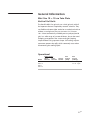
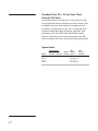
user manual Vertical Gel Electrophoresis Systems Twin Plate Vertical Gel Units Mini Size 10 × 10 cm Twin Plate Vertical Gel Unit, Cat. No. E4100 Mini Size 10 × 10 cm Twin Plate Vertical Gel Unit with Casting Base, Cat. No. E4100-Y Cooled Mini Size 10 × 10 cm Twin Plate Vertical Gel Unit, Cat. No. E4101 Cooled Mini Size 10 × 10 cm Twin Plate Vertical Gel Unit with Casting Base, Cat. No. E4101-Y Standard Size 20 × 20 cm Twin Plate Vertical Gel Unit, Cat. No. E4200 Standard Size 20 × 20 cm Twin Plate Vertical Gel Unit with Casting Base, Cat. No. E4200-Y Cooled Standard Size 20 × 20 cm Twin Plate Vertical Gel Unit, Cat. No. E4201 Cooled Standard Size 20 × 20 cm Twin Plate Vertical Gel Unit with Casting Base, Cat. No. E4201-Y um DNTV100-IM/Rev. A0/08-11 Contents Safety Warnings and Precautions General Information Packing Lists System Details Using the Denville Vertical Gel Electrophoresis Units A. Setting Up the Vertical Unit B. Care and Maintenance C. Gel Plate Preparation D. Gel Plate Assembly E. Casting Using the Gel-running Module F. Casting G. Gel Pouring H. Sample Loading I. Gel and Buffer Volumes/Run Conditions J. At the End of the Run Ordering Information Warranty Disposal ii 1 3 5 6 6 7 8 8 9 10 11 13 14 15 16 18 19 • pi Safety Warnings and Precautions Important user information Please read this entire manual to fully understand the safe and effective use of this product. The exclamation mark within an equilateral triangle is intended to alert the user to the presence of important operating and maintenance instructions in the literature accompanying the instrument. Should you have any comments on this manual, we will be pleased to receive them at: Denville Scientific, Inc. P.O. Box 4588 Metuchen, NJ 08840-4588 Denville Scientific, Inc. reserves the right to make changes in the specifications without prior notice. When used correctly, these units pose no health risk. However, these units can deliver dangerous levels of electricity and are to be operated only by qualified personnel following the guidelines laid out in this instruction manual. The unit must never be used without the safety lid correctly in position. The unit should not be used if there is any sign of damage to the external tank or lid. These units comply with the statutory CE safety directives: 73/23/EEC: low voltage directive: IEC 1010-1:1990 plus amendment 1:1992 EN 61010-1:1993/BS EN 61010-1:1993 • pii General Information Mini Size 10 × 10 cm Twin Plate Vertical Gel Units The Denville Mini Size gel units are a dual-gel unit, with all the important features required by research scientists. They are flexible and come either cooled or un-cooled and with or without a casting base. They can run most 8 × 10 cm or 10 × 10 cm commercially available pre-cast polyacrylamide gels, in a wide range of cassette thickness, due to the novel clamping arrangement. Two screws make gel clamping simple without using separate clamps. Self-sealing snap-on connectors prevent the spills, which commonly occur when disconnecting the cooling liquid. Operational Model Buffer Volume Max Upper Lower Approx. Voltage Chamber Chamber Gel Vol. (Volts) E4100 100 ml 1000 ml 7 ml 80 –150 E4100-Y E4101 E4101-Y Max Current (mAmps) 25 – 45 1 gel 50 – 85 2 gels • p1 Standard Size 20 × 20 cm Twin Plate Vertical Gel Units The Denville Standard Size gel units are dual-gel units, with all the important features required by research scientists. They are flexible and come either cooled or un-cooled and with or without a casting base. The gels are in a large format for increased sample throughput and longer separation. High resolution can be maintained with the excellent cooling features. Self-sealing snap-on connectors prevent the spills, which commonly occur when disconnecting the cooling liquid. Operational Model Buffer Volume Max Upper Lower Approx. Voltage Chamber Chamber Gel Vol. (Volts) E4200 650 ml 3500 ml 35 ml E4200-Y E4201 E4201-Y • p2 Max Current (mAmps) 90 –120 20 – 30 per gel Stacking gel 120 –180 Resolving gel Packing Lists The packing lists should be referred to as soon as the unit is received to ensure that all components have been included. The unit should be checked for damage when received. Be sure to keep all packaging material for damage claims for to use should it become necessary to return the unit. Please contact your supplier if there are any problems or missing items. E4100 Series Mini Size 10 × 10 cm Twin Plate Vertical Gel Units Mini Size 10 × 10 cm Twin Plate Vertical Gel Unit (E4100) Package includes: Tank, lid, gel-running module, a black cable, a red cable, 2× plain glass plates, 2× notched glass plates, 2× 1 mm thick 12-sample combs, 4× 1 mm spacers, 2× spacer aligners, and a dummy plate. Mini Size 10 × 10 cm Twin Plate Vertical Gel Unit with Casting Base (E4100-Y) Package includes: Tank, lid, gel-running module, caster base with silicone seals, a black cable, a red cable, 2× plain glass plates, 2× notched glass plates, 2× 1 mm thick 12-sample combs, 4× 1 mm spacers, 2× spacer aligners, and a dummy plate. Cooled Mini Size 10 × 10 cm Twin Plate Vertical Gel Unit (E4101) Package includes: Cooled tank, lid, gel-running module, a black cable, a red cable, 2× plain glass plates, 2× notched glass plates, 2× 1 mm thick 12-sample combs, 4× 1 mm spacers, 2× spacer aligners, and a dummy plate. Cooled Mini Size 10 × 10 cm Twin Plate Vertical Gel Unit with Casting Base (E4101-Y) Package includes: Cooled tank, lid, gel-running module, caster base with silicone seals, a black cable, a red cable, 2× plain glass plates, 2× notched glass plates, 2× 1 mm thick 12-sample combs, 4× 1 mm spacers, 2× spacer aligners, and a dummy plate. • p3 E4200 Series Standard Size 20 × 20 cm Twin Plate Vertical Gel Units Standard Size 20 × 20 cm Twin Plate Vertical Gel Unit (E4200) Package includes: Tank, lid, gel-running module, a black cable, a red cable, 2× plain glass plates, 2× notched glass plates, 2× 1 mm thick 24-sample combs, 4× 1 mm spacers, 2× spacer aligners, and a dummy plate. Standard Size 20 × 20 cm Twin Plate Vertical Gel Unit with Casting Base (E4200-Y) Package includes: Tank, lid, gel-running module, caster base with silicone seals, a black cable, a red cable, 2× plain glass plates, 2× notched glass plates, 2× 1 mm thick 24-sample combs, 4× 1 mm spacers, 2× spacer aligners, and a dummy plate. Cooled Standard Size 20 × 20 cm Twin Plate Vertical Gel Unit (E4201) Package includes: Cooled tank, lid, gel-running module, a black cable, a red cable, 2× plain glass plates, 2× notched glass plates, 2x 1 mm thick 24-sample combs, 4× 1 mm spacers, 2× spacer aligners, and a dummy plate. Cooled Standard Size 20 × 20 cm Twin Plate Vertical Gel Unit with Casting Base (E4201-Y) Package includes: Cooled tank, lid, gel-running module, caster base with silicone seals, a black cable, a red cable, 2× plain glass plates, 2× notched glass plates, 2× 1 mm thick 24-sample combs, 4× 1 mm spacers, 2× spacer aligners, and a dummy plate. • p4 System Details Usage guidance and restrictions • Maximum altitude 2000 m. • Temperature range between 4 °C and 60 °C. • Maximum relative humidity 80% for temperatures up to 31 °C decreasing linearly to 50% relative humidity at 40 °C. • Not for outdoor use. This apparatus is rated POLLUTION DEGREE 2 in accordance with IEC 664. POLLUTION DEGREE 2, states that: “Normally only non-conductive pollution occurs. Occasionally, however, a temporary conductivity caused by condensation must be expected”. • p5 Using the Denville Vertical Gel Electrophoresis Units A. Setting Up the Vertical Unit Instructions for attaching electrode leads to the lid: 1 Note the position of the lid on the unit. This shows the correct polarity and the correct orientation of the cables, black is negative and red is positive. 2 Remove the lid from the unit. Note if the lid is not removed, fitting the cables may loosen the gold plug and cause damage to the electrode. 3 Screw the cables into the tapped holes as fully as possible so that there is no gap between the lid and the leading edge of the cable fitting. 4 • p6 Refit the lid. B. Care and Maintenance Units are best cleaned using warm water and a mild detergent. Water at temperatures above 60 °C can cause damage to the unit and components. The units should not be left in detergents for more than 30 minutes. The tank should be thoroughly rinsed with warm water and distilled water to prevent build up of salts but care should be taken not to damage the electrode. Vigorous cleaning is not necessary or advised. Air drying is recommended before use. Caution! The units should never come into contact with the following cleaning agents, these will cause irreversible and cumulative damage: Acetone, Phenol, Chloroform, Carbon tetrachloride, Methanol, Ethanol, Isopropyl alcohol, Alkalis. Caution! DEPC is a suspected carcinogen. Always wear gloves and safety glasses. • p7 C. Gel Plate Preparation 1 Clean the plates, spacers and combs in mild laboratory detergent. DO NOT use abrasive creams or scourers. If a particularly clean finish is required (e.g. for silver-stained gels) glass plates can be soaked in chromic acid overnight, rinse with water then wipe successively with ethanol, acetone and ethanol again. NEVER allow organic solvents or chromic acid come into contact with the plastic components. 2 The notched glass plate can be siliconized in a fume hood with dimethyldichlorosilane if required to assist in plate separation after the run. 3 Handle clean plates with gloved hands (remove any fingerprints with acetone). D. Gel Plate Assembly 1 On a clean level bench, position the two side spacers flush with the edges of the rectangular glass plate and then overlay the notched plate. 2 The gel plates can be sealed either with tape, or by clamping greased spacers between the plates with bulldog clips, or by using a casting base (see Casting Using the Gel-running Module, page 9). 3 For tape sealing, hold or clamp the plates firmly and seal the edges of the gel cassette with gel sealing tape. The tape should be applied smoothly with no wrinkles. Reinforce the corners by overlapping extra pieces of tape onto the glass. Grease or fingerprints will prevent a good seal being formed. 4 If greasing is the preferred method, smear a little silicone grease or Vaseline over the spacers before assembly and use the long spacer to seal the bottom of the gel and clamp with bulldog clips. Note that the side spacers will seem too long if this sealing method is chosen. The side spacers should be cut to size — make sure the cut is a clean right angle. • p8 E. Casting Using the Gel-running Module 1 Loosen the clamping plates on the gel-running module by untightening the screws. Place the gel-running module on its side on a level bench surface, and slide the gel cassettes, comprising the glass plates and spacers, into the gel-running module until they meet notched overhangs. The notched glass plates should face the centre of the gel-running module (GRM). Ensure the glass plates are level with the bottom of the GRM. It is important that the plates are square in the GRM and on a flat surface before installing in the caster base (step 4). 2 Put the gel-running module in an upright position on the bench surface. If using plain glass plates without bonded spacers, use the spacer aligner to push the spacers so that they are perfectly aligned with the bottom of the glass plates (there is no need to do this with plain glass plates with bonded spacers). Tighten the screws, using your other hand to hold the plates and spacers in position on the bench surface. 3 Once the gel cassettes are tightened into the gel-running module, invert the gel-running module to check that the plates and spacers are aligned correctly in the gel-running module. Readjust the plates and spacers if necessary. 4 Place the gel-running module onto the casting base with the silicone seals sitting in the grooves and the cam-pin levers pointing into the bench surface. 5 Slot the cam pins into position, turning them in a clockwise direction so that the gel-running module and gel cassettes are drawn onto the silicone seals. The cam pins should then point upwards at 180° to the bench surface. 6 Check for leaks by adding 2 ml distilled water into each gel cassette. The glass plates should be firmly embedded within the silicone seals, ensuring that the gel cassettes remain leak-free. Discard the water and pour the acrylamide gels. • p9 F. Casting 1. Place each plain glass plate on a level bench surface, followed by the spacers and then the notched glass plate. 4. Run your forefinger along the bottom edge of the glass plates to ensure that they are flush with bottom edge of each spacer — if not, repeat step 3. 2. Place the gel-running module (GRM) on its side on the bench and insert the glass plate cassette. Lightly tighten the screws before turning over the GRM to repeat on the other side. 3. If not using plain glass plates with bonded spacers, get a spacer aligner to align the spacers flush with the vertical edges of the plain glass plates before tightening the screws within the GRM. 5. Lower the assembled GRM onto the casting base with the cam pins pointing downwards into the bench surface. 6. Turn the cam pins through 180° to secure the GRM onto the casting base — as you turn the cam pins you will experience increased resistance. 7. Pour the acrylamide gel between the glass plates. 8. Carefully insert the appropriate comb between the glass plates and allow the gel to set for at least 30 minutes. 9. After carefully removing the combs, release the GRM by turning the cam pins in opposite direction on the casting base. 10. Place the GRM into the gel tank, ensuring that there is sufficient buffer to cover the bottom of the glass plates. 11. Fill the inner buffer chamber within the GRM so that it just covers the top of the gel — the gel is now ready to be loaded. 12. Replace the lid and insert the power cables into the power supply, making sure that it is first switched off — the unit is now ready for electrophoresis. • p10 G. Gel Pouring 1 For reproducibility and uniform polyacrylamide crosslinking, we recommend using Electran grade materials and degassing gel solutions before use. Acrylamide solutions should be stored in a cool, dark environment, such as a refrigerator, and allowed to reach room temperature before pouring. Avoid exposure to heat and sunlight. 2 Polymerization conditions should be adjusted to effect polymerization within about 5 –10 minutes. Test a small volume in a vial before pouring the gel. As a rough guide 100 ml of degassed 6% acrylamide gel will set in about 5 minutes at room temperature when gently mixed with 450 µl of freshly prepared 10% (w/v) ammonium persulphate plus 200 µl TEMED. The setting time increases to about 10 minutes if the TEMED volume is reduced to 100 µl, and to approximately 15 minutes with 75 µl. The amount of catalyst may need to be reduced under warm conditions. Do not pour under direct sunlight. 3 Gel pouring can be carried out directly in a gel-casting unit (included with some models and available as optional accessory) or by clamping a taped gel into the tank unit. 4 Run the acrylamide separating gel mix slowly down the inside edge of the gel cassette. Avoid aeration. If a stacking gel is to be used, carefully overlay the separating gel to a depth of 3 – 5 mm with 1× separating gel buffer or water-saturated butanol (If no stacking gel is to be used, insert the required comb into the solution at the top of the gel cassette before polymerization). 5 Following polymerization of the separating gel, pour off the overlay layer (rinse off the butanol with electrophoresis gel buffer) and pour a stacking gel. Insert the comb ensuring bubbles are not trapped. Once the stacking gel has polymerized the gel may be used immediately. • p11 6 If tape has been used, remove the gel tape from the bottom of the gel and from any region that could affect the seal between the glass and the silicone gasket. Clean both the silicone gasket, located on the upper buffer and thebefore outsideconnecting of the gel plates. • The safety lid mustchamber, be in place theIf the gasket becomes unseated from its groove simply press it back power leads to a power supply. into place. Secure the gel plates into position in the • Turn all power supply controls and theplate facing gel running unitoff with thedisconnect short or notched power leads beforeinward. removing the safety lid. DO NOT OVER TIGHTEN the screws as this will cause the glass plates to crack. When running only one • Circulate only water or 50/50 water/ethylene glycol gel, a blank glass plate is required on the other side of the through the heat exchanger. Never introduce antiunit, to retain the top buffer level. Safety information freeze or any organic solvent into any part of the instrument. Organic solvents will cause irreparable 7 Place the gel running unit into the bottom buffer chamber. damage to the unit! IMPORTANT! DO NOT fill above the 8 Add the appropriate volume of running buffer to Maximum fill lines or above the top of upper and lower chambers (seetap General Information, • Do not connect thethe heat exchanger to a water the rectangular gel plate if using glass pagewhere 1). plates smaller than 10 × 10 or cm.any coolant source the water pressure is unregulated. • Do not operate with buffer temperature above 45 °C. All plastic parts are rated for 45 °C continuous duty. Circulate coolant through the heat exchanger during electrophoresis to minimize heating. Overheating will cause irreparable damage to the unit! • Only accessories and parts approved or supplied by Hoefer, Inc, may be used for operating, maintaining, and servicing this product. • p12 H. Sample Loading 1 Samples should be prepared using the relevant sample buffer and procedures. 2 If the sample may contain insoluble material, centrifuge at 12000 × g for 5 minutes. If this stage is omitted samples may streak during electrophoresis. 3 Carefully remove the sample comb and immediately flush the wells with electrophoresis buffer from a syringe. Table 1 provides a guide to the amounts of protein that can be successfully applied when using a Tris Glycine SDS system to a 5-mm wide, 1 mm gel slot. Table 1 Comb Single Band Multiple Bands Sample Vol. 1 mm × 5 mm wide 1– 6 µg 30 – 60 µg < 40 µl 1.5 mm × 5 mm wide 1– 10 µg 50 –100 µg < 60 µl The volumes of sample wells can be estimated by simply multiplying the width, thickness and depth of the well. 4 Load the samples using a gel loading pipette tip. If possible avoid taking liquid from the pellet area at the bottom of the tube. During sample loading the pipette tip should be 1–2 mm above the bottom of the well to minimise dilution of the sample and to keep the sample as a tight layer. 5 Fill unused wells with the equivalent volume of sample buffer to maintain uniform electrical resistance across the gel. 6 Replace the safety lid firmly making sure that the electrical connectors form a good contact. 7 Connect the electrophoresis apparatus to the power pack and connect the power pack to the mains supply. Turn all settings to zero before turning on the mains supply. Adjust the controls to the desired settings. Follow the manufacturer’s instructions. • p13 I. Gel and Buffer Volumes/Run Conditions Guidelines for operating conditions are given in General Information on page 1, however, conditions vary according to the number of gels, their composition, length and cross sectional area. The current required will increase proportionally to the number of gels or gel thickness providing that the voltage is not limiting, e.g. 2 gels require twice the current of 1, but the same voltage. Longer gels require proportionally higher voltages. By increasing the gel concentration the electrical resistance is increased and the rate of migration decreases. Higher voltages may be applied, but take care not to overheat the gel. The conductivity of gels using non-dissociating buffer systems often vary and therefore conditions need to be determined empirically. 1 The run conditions are to be taken as a guideline only and apply to SDS Tris-glycine gels. If the plates become hot reduce the power settings. 2 If a native gel is being used, it may be necessary to pre-electrophorese the gel for 15– 40 minutes prior to sample loading. 3 For SDS gels do not pre-electrophorese the gel. • p14 J. At the End of the Run 1 Stop the run, turn the power supply settings to zero, turn off the power source and disconnect the power leads. 2 Remove the safety lid by gripping the edges and pressing on the locating lugs with your thumbs. 3 Remove the internal gel running unit by lifting vertically. 4 After unclamping the gel and removing the tape (if used), separate the plates with a strong, broad blade (not metal, as this will damage the plates). If you are using notched or eared plates DO NOT pry them apart at the ears. 5 After removing the gel for staining, clean the plates thoroughly and rinse in distilled water. A clean sheet of foam rubber placed in the bottom of the sink serves as a useful support and minimizes the risk of glass plate damage. Safety information 6 Empty the buffer chambers with a vacuum line and trap or carefully decant the buffer away from the electrical connectors. Rinse the chambers with distilled water then • The safety lid must be in place before connecting the dry the electrode connectors with tissue. NEVER USE power leads to a power supply. ORGANIC SOLVENTS. Avoid direct contact of objects with platinum electrodes. Ensure that theoff connectors are •the Turn all power supply controls and disconnect the clean and dry before usage or storage. power leads before removing the safety lid. • Circulate only water or 50/50 water/ethylene glycol throughAcrylic the heat Never introduce antiIMPORTANT! plasticexchanger. is NOT resistant to aromatic freeze orhydrocarbons, any organicketones, solvent intoalcohols any part of the or halogenated esters, solvents cause irreparable (over instrument. 25%) and acidsOrganic (over 25%). They willwill cause “crazing” damage unit! plastic and should NOT be especially of the to UVthe transparent used for cleaning. DO NOT use abrasive creams or scourers. • Do not connect the heat exchanger to a water tap Dry components with clean tissues prior to use. Ensure that or any coolant source where the water pressure is the connectors are clean and dry before use or storage. unregulated. • Do not operate with buffer temperature above 45 °C. All plastic parts are rated for 45 °C continuous duty. Circulate coolant through the heat exchanger during electrophoresis to minimize heating. Overheating will cause irreparable damage to the unit! • Only accessories and parts approved or supplied by Hoefer, Inc, may be used for operating, maintaining, and servicing this product. • p15 Ordering Information E4100 Series Mini Size 10 × 10 cm Twin Plate Vertical Gel Unit Replacement Parts and Accessories Combs 8 Sample wells, 0.75 mm E4122-8MC 10 Sample wells, 0.75 mm E4122-10 12 Sample wells, 0.75 mm E4122-12 16 Sample wells, 0.75 mm E4122-16MC 8 Sample wells, 1.0 mm E4123-8MC 10 Sample wells, 1.0 mm E4123-10 12 Sample wells, 1.0 mm E4123-12 16 Sample wells, 1.0 mm E4123-16MC 8 Sample wells, 1.5 mm E4124-8MC 10 Sample wells, 1.5 mm E4124-10 12 Sample wells, 1.5 mm E4124-12 16 Sample wells, 1.5 mm E4124-16MC 8 Sample wells, 2.0 mm E4125-8MC 10 Sample wells, 2.0 mm E4125-10 12 Sample wells, 2.0 mm E4125-12 16 Sample wells, 2.0 mm E4125-16MC Spacers 0.75 mm Spacer set, 10 × 100 mm E4161 1.0 mm Spacer set, 10 × 100 mm E4162 1.5 mm Spacer set, 10 × 100 mm E4163 2.0 mm Spacer set, 10 × 100 mm E4164 Plates Plain 10 × 10 cm glass with bonded 0.75 mm spacers, pkg/2 E4151 Plain 10 × 10 cm glass with bonded 1 mm spacers, pkg/2 E4152 Plain 10 × 10 cm glass with bonded 1.5 mm spacers, pkg/2 E4153 Plain 10 × 10 cm glass with bonded 2 mm spacers, pkg/2 E4154 Plain glass 10 × 10 cm, pkg/2 E4155-P Notched glass 10 × 10cm, pkg/2 E4155-N • p16 E4200 Series Standard Size 20 × 20 cm Twin Plate Vertical Gel Units Replacement Parts and Accessories Combs 18 Sample wells, 0.75 mm E4222-18MC 24 Sample wells, 0.75 mm E4222-24 36 Sample wells, 0.75 mm E4222-36MC 48 Sample wells, 0.75 mm E4222-48 18 Sample wells, 1.0 mm E4223-18MC 24 Sample wells, 1.0 mm E4223-24 36 Sample wells, 1.0 mm E4223-36MC 48 Sample wells, 1.0 mm E4223-48 18 Sample wells, 1.5 mm E4224-18MC 24 Sample wells, 1.5 mm E4224-24 36 Sample wells, 1.5 mm E4224-36MC 48 Sample wells, 1.5 mm E4224-48 Spacers 0.75 mm Spacer set, 20 × 200 mm E4261 1.0 mm Spacer set, 20 × 200 mm E4262 1.5 mm Spacer set, 20 × 200 mm E4263 Plates Plain 20 × 20 cm glass with bonded 0.75 mm spacers, pkg/2 E4251 Plain 20 × 20 cm glass with bonded 1 mm spacers, pkg/2 E4252 Plain 20 × 20 cm glass with bonded 1.5 mm spacers, pkg/2 E4253 Plain glass 20 × 20 cm, pkg/2 E4255-P Notched glass 20 × 20 cm, pkg/2 E4255-N • p17 Warranty Denville warrants that the unit you have received has been thoroughly tested and meets its published specification. This unit (excluding all accessories) is warranted against defective material and workmanship for a period of twelve (12) months from the date of shipment ex factory. Denville will repair all defective equipment returned during the warranty period without charge, provided the equipment has been used under normal laboratory conditions and in accordance with the operating limitations and maintenance procedures outlined in this instruction manual and when not having been subject to accident, alteration, misuse or abuse. No liability is accepted for loss or damage arising from the incorrect use of this unit. Denville’s liability is limited to the repair or replacement of the unit or refund of the purchase price, at Denville’s option. Denville is not liable for any consequential damages. Denville reserves the right to alter the specification of its products without prior notice. This will enable us to implement developments as soon as they arise. Denville’s products are for research use only. A return authorization must be obtained from Denville before returning any product for warranty repair on a freight- prepaid basis. • p18 Disposal This equipment is marked with the crossed out wheeled bin symbol to indicate that it must not be disposed of with unsorted waste. Instead it is your responsibility to dispose of your equipment correctly at lifecycle-end by handing it over to an authorized facility for separate collection and recycling. It is also your responsibility to decontaminate the equipment in case of biological, chemical and/or radiological contamination, so that the persons involved in the disposal and recycling of the equipment are protected from any potential hazard. For further information about where you can drop off your waste equipment, please contact your local Denville representative. By doing so, you will help to conserve natural and environmental resources and you will ensure that your equipment is recycled in a manner that protects human health. Thank you • p19 Denville Scientific, Inc. P.O. Box 4588 Metuchen, NJ 08840-4588 Toll Free: 1-800-453-0385 Phone: 1-908-757-7577 Fax: 1-908-757-7551 Email: [email protected] Web: www.densci.com © 2011 Denville Scientific, Inc. All rights reserved. Printed in the USA. • p20