1
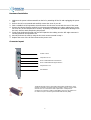
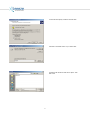
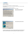
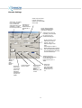
Breeze Technologies Ltd
User Manual
Version 1.0
1
Hardware Installation
1. Make sure the power is disconnected from the PC by switching off the PC and unplugging the power
cord.
2. Refer to the PC’s user manual and carefully remove the cover of your PC.
3. Find a suitable free PCI expansion slot and remove the slot cover screw and slot cover if they exist.
4. Remove the Breeze Encoder carefully from its protective packaging by its edge, making sure you do
not touch any of the components or circuitry. If possible, to prevent any electrostatic discharge onto
the card, wear an earth strap during this process.
5. Firmly press the Breeze Encoder into the PCI Expansion slot making sure the PCI edge connector is
securely seated in the expansion slot.
6. Securely fix down the card by using the slot cover screw removed in step 3.
7. Replace the cover of the PC and reconnect the power cord.
Connector layout
S-Video in & out
Composite in & out
Phono unbalanced Audio Left channel in
Phono unbalanced Audio Right channel in
Mini-jack stereo out
LED indicators
The Breeze Encoder works as an Encoder and Decoder simultaneously. If the
encoder is switched to Composite then the Decoder’s output is on the S-Video
and visa versa. To convert the S-Video output back to a composite for
monitoring we provide an S-Video to RCA adapter as shown. This feature can
be used for Loop Thru monitoring and Decode While Encode (DWE).
2
Driver Installation
Remove the supplied software (PowerStream CDROM) from the box.
On re-booting the PC place the PowerStream CD into your CDROM drive.
1. The Operating system will automatically detect the new hardware
and request a driver.
2. Follow the Hardware Installation wizard. Continue by clicking
‘Next’.
3. Select search for a suitable driver and click ‘Next’.
3
4. Check the box ‘Specify a location’ and click ‘Next’.
5. Browse to the folder ‘driver’ on your cdrom drive
6. Select the file ‘breeze.inf’ and click on ‘Open’. Then
click on OK.
4
7. The following screen is displayed pressed ‘Yes’.
8. And finally on completion of the wizard you will have
the driver installed.
5
Software Installation
There are two key parts to PowerStream. The 'Transmitter' and 'Receiver'.
The Transmitter is loaded onto the host PC and controls the encoder functions. The Receiver is loaded
onto the receive PC.
To install the Transmitter run Setup.exe from the folder;
‘Breeze PowerStream Transmitter’. This is found on your supplied CDROM.
On running ‘Setup’ you will be presented by our
End User License Agreement. If you are happy
with the terms of this license then click ‘Yes’.
Choose a suitable directory to install the software. If
you are happy with the default then just click ‘Next’.
To install the PowerStream receiver follow the exact same process as above for the install software in the
folder ‘Breeze PowerStream Receiver’. The Receiver software should be installed onto other PC on the
network. It can also be installed the same PC as the transmitter for monitoring the received stream.
6
7
MPEG PowerStream
MPEG PowerStream is a streaming solution built around the Breeze Blue MPEG encoder.
•
•
•
•
•
•
Suitable for Broadband & ADSL networks.
Supports Multiple Streams
Unicast, point-to-point, Multicast and Broadcast
Windows Media Player Receiver
Microsoft DirectShow Compatible
MPEG1, MPEG2 support
Applications:
Satellite Distribution
Distance Learning
Corporate Training
Business Television
Surveillance & Monitoring
MPEG PowerStream runs on Windows XP, Windows 2000 or Windows NT 4.0 Service Pack 5.
The Breeze PowerStream application can be found in the Start Menu under Programs. Run the application
MPEG PowerStream from the Programs. The following screen will appear on the computer screen.
Click this button to start a real-time feed
from the Breeze Blue encoder or a file
transfer.
Click this button to stop a real-time feed from the
Breeze Blue encoder or a file transfer.
The encoder should be stopped, by pressing this
button, prior to resetting other configurations.
There are 4 buttons on the application.
Options
The 'options' button provides a pull-down menu which gives access to 3
areas: Settings, Preferences and Schedule.
8
Settings
Settings provides 5 screens:
Net Settings: Provides for network settings such as unicast and multicast.
UDP/RTP, host addresses and so on. When set these also need to be applied with the ‘Apply’ button.
Encoder Settings: where such things as inputs, formats stream types,standards, bit rates, resolution,
audio and so on are set. The particular settings need to be made and applied.
Advanced MPEG settings: CBR/VBR, GOP structure etc.
Video Settings: Video-out through loop-through, decode whilst encode (encoder monitoring), color
bars, display on loss of sync (actually loss of signal). This can be seen when running the encoder.
Remove the video input and these choices will appear on the screens (receiver and transmission side).
Color bars can be enabled to provide an output signal when no input signal is present.
Note: on the rear of the encoder is a red & green LED. The red LED lights
also if there is no video input. A useful way to detect which board in
a rack has lost input - or no input present.
We recommend enabling the TBC at all times. The TBC provides a high degree of stability of the encoder
whilst in operation, and it controls some of the warning signals.
Video Calibration: This is where, if required, such things as brightness, contrast and other video levels
can be set. There is a default button to restore standard settings.
9
Net Settings
This indicates the local IP address of
the Network adaptors installed in
the PC. It allows the user to select a
particular network card if multiple
cards are installed.
This indicates which Protocol will be used. Choose
either UDP or RTP. UDP stands for Unified Datagram
Protocol. RTP stands for Real Time Protocol.
These radio buttons define to transfer type. This can be one
of the following:
Multicast:
IP multicast addresses range from 224.0.1.0 to
238.255.255.255.
Unicast:
Unicast sends traffic from a source to a particular destination
on a network. Unicasted traffic is destined for a unique
address.
Broadcast:
Broadcast traffic is received and processed by all computers
on the network.
Clicking the default button will set the default settings.
All subsequent settings will be destroyed.
This Statistics box indicates the
buffer fullness on the Transmitter.
This is a good indicator of the health
of the Transmission and also can
indicate any failure.
These boxes allow you to enter a port number and
IP Address for the transmission. The port and IP
Address must match on the receiver if you are
using Multicast. If you are using Unicast then the
IP Address must be set to the IP address of the
receiver and the port number must then match on
the transmitter and receiver.
Boundary
TTL-based boundaries prevent the forwarding of IP multicast traffic with a TTL less than a specified value. TTL-based boundaries apply
to all multicast packets regardless of the multicast group. Typically used TTL thresholds are listed below.
TTL Thresholds and Their Scope
TTL Threshold
Boundary
Scope
0
Host
Restricted to the same host.
1
Subnet
Restricted to the same subnet.
32
Intranet
Restricted to the same site.
64
Region
Restricted to the same region.
128
Internet
Worldwide.
255
Unrestricted
Unrestricted in scope.
Therefore, setting a Boundary to Intranet on the Boundary interface prevents the forwarding of IP multicast traffic that is intended to
be restricted to the site. Only regional or beyond traffic is forwarded.
10
Encoder Settings
Video Input. According
to your analog video
source, choose the
appropriate video input,
composite or s-video
from the drop-down list.
Stream Type. Set either
Program, Transport or
System. This is the MPEG
mux format.
Depending on
your local TV
standard choose
either NTSC or
PAL.
Choose between MPEG1,
MPEG2 and MPEG4 video
compression standards
Check this box if you are
trancoding. This will select
the source from the
selected decoding file.
Set the resolution of the
Video that you wish to
encode. This is the
width and height of the
video
Closed Caption. Enable or
disable Closed Caption insertion.
This will embed Closed Captions
into the MPEG stream according
to ATSC standard A/53.
Specify the
desired
video
bitrate in
Mbit/s
Choose the
Audio Input
Lite Blue has
phono only.
Deep Blue
has Balanced
and phono or
Digital.
Sampling Frequency.
Set the sampling frequency
of the audio capture.
Choose from 32,44.1 or
48kHz.
Choose the Audio
Bitrate in kbps.
Select the audio
compression
required from
MPEG1,
MPEG2,AC3, AAC
or PCM
11
Audio Layer.
Choose the
appropriate audio
layer in the MPEG
standard from 1,2
or 3
Advanced MPEG Settings
This page is used to set advanced features of the Breeze MPEG encoder.
This enables variable Bitrate. The
Average Bitrate can be selected up to
the maximum bitrate defined by the
Video Bitrate in the Encoder Settings
GOP Structure. Define the distance
between corresponding I frames (N)
and the distance between I and P
frames (M). So if M is set to 3 and I is
set to 12 then an I frame is inserted
every half a second for PAL. Setting
this to 15 will give a similar value for
NTSC. The sequence of frames will be
IBBPBBPBBPBBI for PAL.
If you are encoding Transport Streams
then these are the default Program Ids for
the Video and Audio. These are used to
identify the Video and Audio elementary
streams within the Transport Mux. The
Program Number is used to define these
streams in the Program Map Table (PMT).
Define the individual
Elementary Stream Ids.
12
Video Calibration
This page is used to set the Sharpness, Brightness,
Contrast, Saturation, Hue and Gamma for the video
input. All settings can be adjusted in real-time. The
Default button sets the adjustments back to their
defaults.
13
Video Settings
Video Out. Use the Check box to Disable
or Enable Video Out. This can be used
for Loop Thru which loops the video or
for Decode-while-encode for monitoring
the actual encoding. Loop Thru
monitors the video after TBC and
conditioning. You will need to use the Svideo to composite converter (as shown
in hardware installation) if you are
going into the encoder s-video the loopthrough signal can be picked-up from
the composite (BNC) output.
Time Base Correction. Enable this
for either VCR (unstable) or
Broadcast signals (stable). This
makes sure the video signal is
consistent by cleaning the Video
input by inserting correct VSYNCs
and re-timing the video.
Color Bars can be displayed
either continuously or on loss
of Sync i.e. loss of video.
Warning messages can be
displayed along with Color bars
if loss of Sync i.e loss of video is
detected. Enter the text to be
displayed.
On Screen Display. This allows real-time
text to be displayed during the encoding
process. You can position the text using
the x and y positions. To remove the
text click on ‘Clear’. To add the text click
on ‘Set’.
14
Preferences
The 'Preferences' screen enables settings for streaming and archiving.
Auto Start allows the encoder to
automatically start when the
application is run.
Stream to Network. When this is
enabled MPEG is delivered over
the network as a stream defined
by the settings on the Network
Settings page.
Stream from File allows an MPEG file to be
“pumped” onto the network. Use the
‘Change” button to browse to a file on the
hard disk drive. If the loop box is checked
then the file is repeated continuously.
Write to Disk. Enabling ‘Write to
Disk’ allows a file to be created on
the Hard Disk drive. Use “Change’ to
browse to the file to be written. This
can be used simultaneously with
Stream to Network.
Select a file to decode. Select a file to
decode. This file will be decoding thru
the video out. Use ‘Change’ to browse
for the file to use on the hard disk
drive. Decoding and encoding can be
done simultaneously as long as the
Decode-while encode feature is not
enabled in the Video Settings pages.
If ‘Transcode’ is enabled then the
decoded stream is used as the source
for the encoder.
15
Schedule
This page allows a schedule encoding to take place. Once
enabled, this will allow a stream to be delivered at a
particular time of day.
16
PowerStream Receiver
MPEG PowerStream uses Windows Media Player as its receiver.
In Media Player 6.4 select File and
then choose ‘Open’.
You are then presented with the Open box.
Type in the URL. BLUE://
For multicasting this is the multicast IP address
and port number defined by the Transmitter.
e.g BLUE://224.1.1.1:11111
For a unicast the port number is only needed.
The syntax for this is:
BLUE://11111
17
For Windows Media Player 9.0, select File
and then ‘Open URL’.
You are then presented with the Open URL box.
Type in the URL. BLUE://
For multicasting this is the multicast IP address and
port number defined by the Transmitter.
e.g BLUE://224.1.1.1:11111
For a unicast the port number is only needed. The
syntax for this is:
BLUE://11111
18