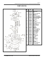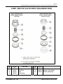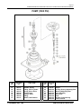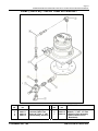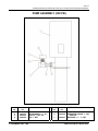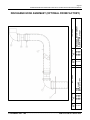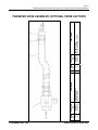
1
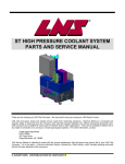
HIGH PRESSURE COOLANT SYSTEM PARTS AND SERVICE MANUAL Thank you for choosing an LNS Chip Conveyor. We are proud to have you among our LNS family of users. LNS Chip Conveyors simply and reliably remove waste from machining operations. Machine efficiency is increased and operator safety is improved since the conveyor work with little operator attention and without interrupting production time. LNS Conveyors are available for many types of machine tools or other applications. They can be arranged to deliver wet or dry waste to containers or to conveyor or chute-type disposal systems. For further information, contact: Inside Sales Department LNS TURBO 203 Turbo Drive Kings Mountains, NC 28086 This Service Manual is intended to assist with the normal maintenance that will assure long service life of your LNS Chip Conveyor. It is in two parts – a Service Instruction Section, followed by a Parts Section, which includes drawings and parts lists for the basic elements of the conveyors. © DECEMBER 2003– LNS PUBLICATION NO. 864510-0015 T Page 1 POWERSTREAM HIGH PRESSURE COOLANT SYSTEM PARTS AND SERVICE MANUAL NOTICE ALL INFORMATION CONTAINED IN THIS MANUAL IS INTENDED TO BE CORRECT; HOWEVER INFORMATION AND DATA IN THIS MANUAL ARE SUBJECT TO CHANGE WITHOUT NOTICE. LNS MAKES NO WARRANTY OF ANY KIND WITH REGARD TO THIS INFORMATION OR DATA. FURTHER, LNS IS NOT RESPONSIBLE FOR ANY OMISSIONS OR ERRORS OR CONSEQUENTIAL DAMAGE CAUSED BY THE USER OF THE PRODUCT. LNS RESERVES THE RIGHT TO MAKE MANUFACTURING CHANGES, WHICH MAY NOT BE INCLUDED IN THIS MANUAL. LNS supplies data necessary for the proper instruction, test, operation and maintenance of this product. LNS retains all proprietary rights in and to the information so disclosed and such shall not be reproduced, copied, or used in whole or in part for purposes other than those for which it is furnished. 1. TABLE OF CONTENTS CONTENTS Introduction & Table of Contents . . . . . . . . . . . . . . . . . . . . . . . . . . Instructions for Ordering Parts . . . . . . . . . . . . . . . . . . . . . . . . . . . . Warranty . . . . . . . . . . . . . . . . . . . . . . . . . . . . . . . . . . . . . . . . . . . . Benefits of High Pressure Coolant . . . . . . . . . . . . . . . . . . . . . . . . High Pressure Coolant Requirements/Considerations . . . . . . . . . Features of PowerStream High Pressure Coolant System . Standard Features . . . . . . . . . . . . . . . . . . . . . . . . . . . . . . . . . . . . Performance Characteristics (Standard System) . . . . . . . . . . . . Optional Equipment . . . . . . . . . . . . . . . . . . . . . . . . . . . . . . . . . . . Size Information . . . . . . . . . . . . . . . . . . . . . . . . . . . . . . . . . . . . . . Installation Instructions . . . . . . . . . . . . . . . . . . . . . . . . . . . . . . . . . . System Schematic . . . . . . . . . . . . . . . . . . . . . . . . . . . . . . . . . . . . Prestart-Up Procedures . . . . . . . . . . . . . . . . . . . . . . . . . . . . . . . . . Maintenance Procedures: . . . . . . . . . . . . . . . . . . . . . . . . . . . . . . Duplex Filter Maintenance Procedure . . . . . . . . . . . . . . . . . . Pressure Switch Installation & Maintenance . . . . . . . . . . . . . . Level Switch Installation & Maintenance . . . . . . . . . . . . . . . . . High Pressure Pump (1000 PSI) Maintenance . . . . . . . . . . . . Trouble Shooting . . . . . . . . . . . . . . . . . . . . . . . . . . . . . . . . . . . . . . Maintenance Schedule . . . . . . . . . . . . . . . . . . . . . . . . . . . . . . . . . PowerStream® Service Parts. . . . . . . . . . . . . . . . . . . . . . . . . . . . . PowerStreamElectrical Information . . . . . . . . . . . . . . . . . . . . . . . . PAGE 1 2 2 3 3-4 4 5 5 6 6 7 8 9 10-20 10 11 12 13-20 21-24 25 26-40 41-42 2. INSTRUCTIONS FOR ORDERING PARTS © DECEMBER 2003– LNS ................................................................................ PUBLICATION NO. 864510-0015 Page 2 POWERSTREAM HIGH PRESSURE COOLANT SYSTEM PARTS AND SERVICE MANUAL INSTRUCTIONS FOR ORDERING PARTS Furnish the following information on your order: • Model and serial no. of machine • Catalog number and name of part • Quantity wanted • Purchase order number • Bill to address Furnish exact shipping instructions: • Complete shipping address • Mode of delivery • Parcel post, truck line, etc How to find the model and serial number of your machine: The machine model number and serial number is stamped on the machine nameplate located on the motor cover. DIRECT YOUR ORDER TO: LNS Turbo 203 Turbo Drive Kings Mountains, NC 28086 U.S.A. Telephone: (704) 739-7111 Fax: (704) 739-6039 WARRANTY Seller warrants that within 12 months from original shipment, if its products are operated by the original specified user: Seller will repair or replace, at its option, free of charge except freight, FOB shipping point, any parts it finds nonconforming on these conditions: a. on request, user promptly allows seller to inspect, and user returns all requested parts to seller’s plant, and b. user has operated and maintained products in accordance with seller’s maintenance and operational literature and good business practice; and c. products have not been misused, abused, damaged by accident or altered without seller’s written consent; and d. user employs trained maintenance and operating personnel; and e. buyer meets all payment obligations; Seller warrants products manufactured by others to the extent warranted by their original manufacturers, on these conditions. Parts, which have expected life shorter than one year under normal usage, are excluded. USED PRODUCTS ARE SOLD AS IS. SELLER MAKES NO WARRANTY FOR USED PRODUCTS EXCEPT AS TO TITLE. BUYER MAY INSPECT AND TEST BEFORE SHIPMENT AND ACCEPTS USED PRODUCTS ON THESE TERMS. THIS WARRANTY IS EXCLUSIVE AND IN LIEU OF ALL OTHER WARRANTIES WHETHER WRITTEN, ORAL, OR IMPLIED, (INCLUDING ANY WARRANTY OF MERCHANTABILITY OR FITNESS FOR PARTICULAR PURPOSE.) © DECEMBER 2003– LNS ................................................................................ PUBLICATION NO. 864510-0015 Page 3 POWERSTREAM HIGH PRESSURE COOLANT SYSTEM PARTS AND SERVICE MANUAL BENEFITS OF HIGH PRESSURE COOLANT 1. CYCLE TIME The introduction of high pressure coolant at the tool to part interface allows the cutting fluid to do its job more effectively. With lower pressures, the coolant does not effectively cool the shear zone; rather most heat is dissipated via conduction to material around the shear zone. Higher pressures allow the coolant to dissipate heat at the cut more directly enabling higher metal removal rates and, therefore lower cycle times. 2. TOOL LIFE Properly applied high pressure coolant helps to break chips and evacuate them from the cutting area. This minimizes re-cutting of chips. Along with more effective cooling, this not only reduces tool wear; it also makes tool life more predictable. Tooling wears, it doesn’t fail from chip damage and heat. 3. PART FINISH Elimination of chip re-cutting, higher metal removal rates, more effective cooling, predictable tool wear, along coolant filtration all contribute to a better surface finish. 4. • • • • • OTHER Improved accuracy by the reduction of chips contaminating the tool holder to spindle taper interface. Improved chip evacuation from fixtures and the machining area. Improved machining capability / range (e.g. Larger L/D ratios, higher metal removal rates, etc.). Improved through-put by combining operations on a single machine / set-up (e.g. milling and deep drilling). Improved capabilities with ‘exotic’ material and tooling. © DECEMBER 2003– LNS ................................................................................ PUBLICATION NO. 864510-0015 Page 4 POWERSTREAM HIGH PRESSURE COOLANT SYSTEM PARTS AND SERVICE MANUAL HIGH PRESSURE COOLANT REQUIREMENTS / CONSIDERATIONS 1. MACHINE CAPABILITY The machine tool coolant path (spindle seals, rotary unions, hose, fittings, etc.) must be suitable for the pressure applied. The machine components must have a working pressure rating equal to or greater than the maximum coolant pressure supplied. 2. MACHINE ENCLOSURE Higher pressure at the tool along with faster metal removal rates may produce more splash and coolant atomization (mist) depending on the machining process. 3. FILTRATION Most spindle OEM’s recommend that coolant should be filtered to between 10 and 30 microns for proper operation of their systems. This higher filtration also improves part finish and tool holder to spindle accuracy (less contamination). Most machine tool manufacturers provide a ‘police filter’ in the coolant path, near the machine tool spindle. This filter functions as a back-up filter downstream of the main filters to insure against stray contamination from the coolant hoses, fitting sealant, improper filter media in the main filters and etc. Such a filter usually has a nominal filtration level significantly higher (less filtration) than the main coolant filters. As such, it should not require attention except during periodic system cleaning. It is recommended to insure the machine is equipped with such a filter. 4. HEAT Properly applied coolant absorbs much of the heat generated in the cutting zone. High pressure coolant enables more effective cooling which allows a higher metal removal rate which, in turn, results in more heat transferred to the coolant. A high-pressure pump may also introduce heat to the coolant. In some cases, the process dictates the use of an external cooling mechanism. LNS’ ‘clean coolant’ reservoir provides an effective heat dissipation mechanism. This eliminates the need for additional cooling equipment in many cases. © DECEMBER 2003– LNS ................................................................................ PUBLICATION NO. 864510-0015 Page 5 POWERSTREAM HIGH PRESSURE COOLANT SYSTEM PARTS AND SERVICE MANUAL FEATURES OF POWERSTREAM HIGH PRESSURE COOLANT SYSTEMS ‘STANDARD’ POWERSTREAM SYSTEM The standard PowerStream coolant system uses a low pressure pump to transfer coolant from the main, machine tank through a duplex filter system to a holding tank. A high pressure pump delivers filtered coolant from the holding tank to the machine. The duplex filter system consists of a pair of canister filters with a manual valve to direct the incoming flow to one canister at a time. As contamination collects in the filter element, resistance to flow causes the pressure drop across the filter to increase. The system incorporates a pressure switch to indicate that the filter requires service. Incoming flow can be directed to the ‘clean’ filter canister and the element in the ‘dirty’ one can be replaced without taking the system out of operation. The filter canisters are integral to a holding tank (no downstream plumbing). A high-pressure pump draws filtered coolant from the holding tank and delivers it to the machine. The coolant supply to the high pressure pump is supplied by an ‘open system’, i.e. it is not pressurized or fixed flow. Consequently, the transfer pump flow rate is somewhat independent of the high pressure pump flow rate. That means the transfer pump does not have to be synchronized with the high pressure pump. This provides significant advantage over in-line filters or ‘closed’ systems in which one is forced to choose between lag time and transfer pump churning (dead heading). The holding tank incorporates at least one level switch to provide an alarm signal if the level of filtered coolant in the tank drops to an unacceptable level. This could indicate a failure of the transfer pump or complete blockage of the filters. Additional level switches may be on the unit depending upon the machine tool interface. Excess filtered coolant overflows from the holding tank back to the main tank. The system can be used to filter the main coolant tank even if the high pressure pump is not being used, i.e. to polish coolant in the main tank. Additional sensors may be integrated for specific applications. The ‘standard’ PowerStream system is a straight forward, stand-alone design which provides a high level of functionality with a low level of complexity. © DECEMBER 2003– LNS ................................................................................ PUBLICATION NO. 864510-0015 Page 6 POWERSTREAM HIGH PRESSURE COOLANT SYSTEM PARTS AND SERVICE MANUAL STANDARD FEATURES □ Pressure up to 1000 psi (manually adjustable) □ Flow up to 8 gpm □ Other flow and pressure combinations available by request. □ Duplex filter set Open to / built into tank No external plumbing downstream of filters Less agitation No timing issues with transfer pump / starving HP pump Eliminates churning at transfer pump □ Widely used, Service proven, durable pump and regulating valve □ System built and serviced by LNS □ Simple installation □ Ability to filter main tank without running HP pump (polish main system coolant) □ Easily retro-fit to virtually any coolant system Integral System Option □ Filtered, holding tank integral with conveyor / machine tank. □ Electrical control box integral with conveyor box □ Integrated system provides ‘clean’ look with minimal floor space requirements □ Entire chip and coolant system built and serviced by LNS □ Easy installation. ‘One-piece’ tank for conveyor and high pressure system. PERFORMANCE CHARACTERISTICS (Standard System) Filtration 10um standard. 5 to 200 optional. Transfer / Filtration Flow 12-15 gpm Transfer Pressure < 25 psi High Pressure Flow 8 gpm Maximum Pressure 1000 psi Control Input machine tool m-codes to suit user Control Output 24 VDC or 110 VAC signals Consult Factory For Other Pressures Flow Rates And Capacities. © DECEMBER 2003– LNS ................................................................................ PUBLICATION NO. 864510-0015 Page 7 POWERSTREAM HIGH PRESSURE COOLANT SYSTEM PARTS AND SERVICE MANUAL OPTIONS Discharge Hose Assy Transfer Hose Assy Transfer Pump Alternative Pressure and Flow Filtration 62905005 62905004 Consult Factory Consult Factory 5 um 98731130 10 um 98731127 (Standard if not specified by customer) 25 um 98731131 50 um 98731132 100 um 98731133 200 um 98731134 SIZE STAND ALONE UNIT (1000 psi / 8 gpm) (As Shown in Layout Below) Overall Size Length Width Height Nominal Volume Volume INTEGRAL UNIT Overall Size Nominal Volume 40 in 30 in 51 in 82 gal 1016 mm 762 mm 1295 mm 310 liters (1000 psi / 8 gpm) L W H V 29 30 43 41 in in in gal 737 762 1092 155 mm mm mm liters © DECEMBER 2003– LNS ................................................................................ PUBLICATION NO. 864510-0015 Page 8 POWERSTREAM HIGH PRESSURE COOLANT SYSTEM PARTS AND SERVICE MANUAL POWERSTREAM INSTALLATION INSTRUCTIONS STANDARD UNITS 1) Inspect for shipping damage. 2) Position the unit and connect to the machine tool and main coolant tank. The proper location for the PowerStream unit must accommodate the following connections to the machine tool and its main coolant tank. a) High Pressure Outlet • Plumb the machine’s high pressure line to the outlet of the pump assy. • The 1000 psi pump assembly terminates in a ¾ inch NPT female connection. • The 200 psi pump assembly terminates in a 1 inch NPT female connection. b) Overflow Discharge – Clean Coolant Connect the overflow (2 inch NPT female) to the machine tank. The optional Discharge Hose Assembly provides all hardware to accomplish the connection. During normal operation, the PowerStream unit may filter more coolant than is used by the high pressure pump. This excess will flow back to the machine tank. Note that this is a gravity drain and the machine tank fluid level must be lower than the PowerStream overflow for proper operation. • • • c) Transfer Pump – Dirty Coolant In Connect the Duplex Filter inlet (1 inch NPT female) to a suitable coolant supply. The optional Transfer Pump Assembly and Transfer Hose Assembly provide all hardware to accomplish the connection. • If the Transfer Pump Assembly is not used, the customer must furnish a pump that supplies adequate flow for the selected high pressure pump at a head of 15 psi and develops a maximum pressure of no more than 35 psi. • If the Transfer Hose Assembly is not used, it is recommended to install a check valve near the transfer pump to prevent drain back of fluid when the transfer pump is off. • • d) Electrical / Control connections vary with control options. Make the necessary connections. 3) Prepare the canister filters. Open both filter canisters, check for and remove any foreign material from shipping and insert the proper filter elements. See ‘Duplex Filter Maintenance Procedure’. 4) Fill the tank with filtered coolant. The unit is equipped with a number of level sensors that interface with the machine tool control the fluid level in the PowerStream tank during normal operation. Depending on the particular machine tool control, the tank may have to be filled manually at installation. Use the transfer pump or other means to pump coolant through a properly prepared canister filter until coolant starts to flow through the discharge (overflow) line. 5) Prepare the high pressure pump as necessary. Refer to the pump operation manual. 6) Set the high pressure relief valve (not included on 200 psi units). Turn the adjusting screw all the way out (counter clockwise). This sets the valve to the minimum pressure for bypass. Initiate a high pressure cycle on the machine tool (refer to machine tool requirements for high pressure operation). Observe the pump pressure gauge and turn the pressure relief valve adjusting screw clockwise until the desired pressure has been reached. © DECEMBER 2003– LNS ................................................................................ PUBLICATION NO. 864510-0015 Page 9 POWERSTREAM HIGH PRESSURE COOLANT SYSTEM PARTS AND SERVICE MANUAL HIGH PRESSURE SYSTEM SCHEMATIC © DECEMBER 2003– LNS ................................................................................ PUBLICATION NO. 864510-0015 Page 10 POWERSTREAM HIGH PRESSURE COOLANT SYSTEM PARTS AND SERVICE MANUAL SERVICE SECTION BEFORE INITIAL START-UP HIGH PRESSURE PUMP (1000 PSI) Before you start the pump, be sure that: • The pipe plug on the pump housing has been removed and the oil reservoir has been installed. The reservoir allows for oil expansion during pump operation. At startup, there is normally no oil in the reservoir; during operation, oil rises in the reservoir (the level will depend on operating conditions). • All shut-off valves are open, and the pump has an adequate supply of fluid. • All connections are tight. • The pressure regulator on the pump outlet is adjusted so the pump starts under minimum pressure. This allows air in the system to be expelled easily, and fluid to enter the pump and system. • The coupler that connects the pump and motor has been sized and installed correctly. IMPORTANT PRECAUTIONS Adequate Fluid Supply. To avoid cavitation and premature pump failure, be sure that the pump will have an adequate fluid supply and that the inlet line will not be obstructed. Shut-Off Valves. Never install shut-off valves between the pump outlet and discharge pressure regulator, or in the regulator bypass line. Freezing Conditions. Protect the pump from freezing. See also the Maintenance Section. • All guards and safety covers have been installed. • All electrical wiring has been done correctly to electrical codes. INITIAL START-UP PROCEDURE HIGH PRESSURE PUMP (1000 PSI) 1. Turn on power to the pump motor. 2. Listen for any erratic noise, and look for unsteady flow. 3. Adjust the discharge pressure regulator to the desired operating and bypass pressures. 4. After the pressure regulator is adjusted, set the “pop-off” safety relief valve at 100 psi (7 bar) higher than the desired operating pressure. © DECEMBER 2003– LNS ................................................................................ PUBLICATION NO. 864510-0015 Page 11 POWERSTREAM HIGH PRESSURE COOLANT SYSTEM PARTS AND SERVICE MANUAL DUPLEX FILTER MAINTENANCE PROCEDURE SYSTEM DESCRIPTION The duplex filter system consists of a pair of canister filters with a manual valve to direct incoming coolant flow to one canister at a time. As contamination collects in the filter element, resistance to flow causes the pressure drop across the filter to increase. The system incorporates a pressure switch to indicate when the filter requires service. The filter canisters are integral to a holding tank (no downstream plumbing) and open to atmospheric pressure at their outlets. Incoming flow can be directed to the ‘clean’ filter canister and the element in the ‘dirty’ canister can be replaced without taking the system out of operation. The pressure switch is set at the factory to approximately 15 psig. This setting may be adjusted in the field to tailor operation to a specific procedure, but the switch should always be set to activate at or below 20 psig. Furthermore, incoming flow should never exceed 40 psig. MAINTENANCE PROCEDURE To replace the filter element in one canister: 1. Use the manual valve to direct incoming flow to the other canister. 2. Press the “Filter Reset” button on the PowerStream control panel if so equipped. 3. Open the bleed off valve to vent any residual pressure to tank. (NOTE 1) 4. Inspect the canister pressure gauge to ensure pressure has reached zero. 5. Loosen the eye nut on each of the 3 canister lid swing bolts 6. Swing the canister lid away from the canister body to expose the inside of the canister and filter element. □ Take care not to damage the o-ring situated in the canister flange. □ Take care to prevent contamination from the used filter element, coolant inlet area or external sources from entering the canister during the rest of this procedure. 7. Remove the used filter element from the filter basket in the canister and discard in an approved manner. 8. Place a new filter element in the filter basket. Ensure that the filter element ring is seated against the filter basket flange and canister walls. 9. Inspect the canister lid and canister flange. Ensure they are clean and undamaged. 10. Inspect the canister o-ring and ensure it is clean, undamaged, and properly seated. Lubricate with Viton compatible grease as needed. 11. Replace the canister lid. 12. Position canister lid swing bolts and tighten the eye nuts hand tight. 13. Close the bleed off valve. (NOTE 1) 14. This canister is now ready for service. When the second canister requires service, the same procedure is followed for that canister. NOTE 1. This step applies only on units equipped with optional ‘bleed-off’ valves. © DECEMBER 2003– LNS ................................................................................ PUBLICATION NO. 864510-0015 Page 12 POWERSTREAM HIGH PRESSURE COOLANT SYSTEM PARTS AND SERVICE MANUAL PRESSURE SWITCH INSTALLATION & ADJUSTMENT To install the switches, use a suitable wrench on the port and plumb into place with the proper sealant. For electrical wiring, refer to wiring codes below and to the specification sheet for the switch ratings. For low DC loads (<50 mA, TTL logic) use switches with gold contacts. The switch installed on the high pressure unit is adjustable but has been preset at the factory to 15 +/- 2 PSIG prior to shipping the unit. In case a replacement is orderrd, follow the following procedures. All switches are maintenance-free. Adjusting the Set point A) B) For DIN Connector Style Switches Remove DIN connector, then remove the top cover. Remove center screw with female internal thread Then follow the steps below. 1) All non-DIN models have an outer 1/8” Allen head cap that must be removed to allow access to the 1/8” Allen adjustment screw. Using a 1/8 inch Allen (Hex) wrench, adjust clockwise to increase the set point and counterclockwise to lower the set point, which is 15 PSIG (+/- 2 PSIG), while applying this pressure and monitoring the switch’s state.) 2) After verifying the set point re-assemble the switch. Leads Black Green Red Wiring Code DIN #1 Common #2 Normally closed #3 Normally open © DECEMBER 2003– LNS ................................................................................ PUBLICATION NO. 864510-0015 Page 13 POWERSTREAM HIGH PRESSURE COOLANT SYSTEM PARTS AND SERVICE MANUAL LIQUID LEVEL SWITCHES INSTALLATION AND MAINTENANCE INSTALLATION Operation is stated in the tank dry position. NC OPERATION: Stainless Steel Floats: Witness mark (round circle) down. NO OPERATION: Stainless Steel Floats: Witness mark (round circle) up. MAINTENANCE Maintenance should consist of inspection to see that the float is free to move and not coated with any substance, which would change its weight or volume significantly. If this occurs, the float should be removed for cleaning. This is easily accomplished without disturbing the installation. In addition, the stem may be wiped down to remove any build-up. (Make sure float is replaced in the same orientation). The only repair possible in the field is replacement of either the float or stem. Dents or nicks on the float are usually of no consequence to operation. STANDARD STAND ALONE UNIT FLOAT DIMENSIONS (3 FLOATS) See the attached view of the standard Stand-Alone High Pressure Unit showing the float dimensions (Inch/Metric)for units that have 3 float switches. Depending upon the Machine Tool Interface, less float switches may be installed. © DECEMBER 2003– LNS ................................................................................ PUBLICATION NO. 864510-0015 Page 14 POWERSTREAM HIGH PRESSURE COOLANT SYSTEM PARTS AND SERVICE MANUAL HIGH PRESSURE PUMP MAINTENANCE (1000 PSI) DAILY Check the oil level and the condition of the oil. When the pump is operating, the oil in the pump housing gets warm and expands, filling into the oil reservoir. Depending on the type of oil and the operating temperature of the system, the oil level will vary in the reservoir. If there is no oil in the reservoir when the system has reached operating temperature, add oil through the fill cap on the reservoir. Fill the reservoir about 25% full. If the pump is too full of oil, it will overflow the reservoir and reach equilibrium. This is no cause for concern. When the unit is shut down and the oil has cooled, the oil will drain out of the reservoir and back into the pump housing. Use the appropriate motor oil for the application (refer to the chart below). Your unit was shipped from the factory with Hydra-Oil Standard Grade 10W30 weight oil. This oil is designed for lower temperatures and lighter loads. It maintains consistent viscosity over a wide temperature range and repeated cold start-ups. If your high-pressure pump is going to run for continuous use at higher loads and temperatures, 40W oil is recommended, since it provides exceptional wear resistance and film thickness in extended high temperature applications. However, most machining operations do not require continuous high-pressure coolant requirements. OIL RECOMMENDATION PUMP MODEL: OIL RESERVOIR CAPACITY: STANDARD DUTY APPLICATIONS: CONTINUOUS DUTY APPLICATIONS: COLD TEMPERATURE/SEVERE DUTY: HIGH TEMPERATURE/SEVERE DUTY: OIL CHARACTERISTICS Gravity, API @ 60° F Flash Point °F Fire Point °F Pour Point °F Viscosity: SUS @ 100°F SUS @ 210°F Viscosity Index D-10 1.10 U.S. QUARTS (1.05 LITERS) 10W30 OIL 40W OIL 5W/30 SYNTHETIC OIL 15W/50 SYNTHETIC OIL Standard Grade 10W30 40W 31.1 28.7 400 430 440 470 -30 10 360 811 63 85 148 107 Synthetic Grade 5W30 15W50 30.4 30.2 445 470 N/A N/A -65 -55 265 556 60 90 165 170 CAUTION: If you are losing oil but don’t see any external leakage, or if the oil becomes discolored and contaminated, one of the diaphragms (90A-70) may be damaged. Refer to the Service Section. Do no operate the pump with a damaged diaphragm. CAUTION: Do no leave contaminated oil in the pump housing or leave the housing empty. Remove contaminated oil as soon as discovered, and replace it with clean oil. This will help prevent corrosion of internal pump components. © DECEMBER 2003– LNS ................................................................................ PUBLICATION NO. 864510-0015 Page 15 POWERSTREAM HIGH PRESSURE COOLANT SYSTEM PARTS AND SERVICE MANUAL PERIODICALLY Change the oil after the first 100 hours of operation, and every 1000 operating hours thereafter. To change the oil: 1. Disconnect or lock out the electrical power to the pump motor. 2. Remove the access plate on the tank, so there is room to hinge the pump/motor to the horizontal position. 3. Remove the four bolts that hold the pump base to the tank. 4. Hinge the pump/motor to the horizontal position, and support it in that position. 5. Place a pan under the pump oil drain. Remove the drain plug (90A-80) and fill plug (90A-78) from the pump housing. The drain plug is magnetic – clean any metal from the magnet on the plug. CAUTION: Do not turn the drive shaft while the oil reservoir is empty. 6. When the oil has drained, reinstall the drain plug (90A-80). Refill with the appropriate oil, and install the fill plug (90A-78). Tighten to 25 ft/lbs (30 N-m). 7. Hinge the pump/motor back to the vertical position. Reinstall the four bolts that held the pump base to the tank, and reinstall the access plate. 8. Restore the electrical power. 9. Follow the “Initial Startup Procedures,” . CAUTION: Protect the pump from freezing. Refer also the “Shutdown Procedure”. 1. SHUTDOWN PROCEDURE During Freezing Temperatures Disconnect the inlet and outlet piping from the pump. 2. Remove the drain plug (90A-53) at the bottom center of the manifold. 3. Open any draincocks in the piping. 4. Start the pump, and allow it to run until all fluid is removed from the pump head. 5. Stop the pump, and reinstall the drain plug. 6. Fill the pump with antifreeze. When you put the pump back into service, thoroughly flush the antifreeze. SERVICE (FLUID END) This section explains how to disassemble and inspect all easily-serviceable parts of the high pressure pump. Repair procedures for the hydraulic end (oil reservoir) of the pump are included in a later section of the manual. CAUTION: Always disconnect power from the motor before doing maintenance on the pump or motor. CAUTION: Do not disassemble the hydraulic end unless you are a skilled mechanic. CAUTION: The two bolts (item # 38 shown on page 33 exploded view) that screw through the back of the housing into the cylinder casting hold the casting over the hydraulic end of the pump. Do not remove them except when repairing the hydraulic end. © DECEMBER 2003– LNS ................................................................................ PUBLICATION NO. 864510-0015 Page 16 POWERSTREAM HIGH PRESSURE COOLANT SYSTEM PARTS AND SERVICE MANUAL 1. Hinge Pump to Horizontal Position. 2. Disconnect all Electrical Connections (or lock out power to the unit). 3. Remove Manifold (90A-56), Valve Plate (90A-66). a. Remove all nuts (90A-81), bolts (90A-54), and washers (90A-55) around the manifold. Do not remove the two bolts (item # 38 shown on page 33 exploded view) that are installed through the back of the pump housing. b. Use a 10-mm hex Allen wrench to remove the pump centerbolt (90A -51) and its washer (90A-52) in the center of the manifold. CAUTION: Do not turn the pump drive shaft while the manifold and valve plate are off the pump, except when removing diaphragms or repriming the hydraulic cells. c. Remove the manifold (90A-56). The valve plate (90A-66) will remain on the cylinder housing (90A74). d. Inspect the manifold for warping or wear around the inlet and outlet ports. If wear is excessive, replace the manifold or return it to Wanner Engineering for resurfacing. To check if the manifold is warped, remove the O-rings and place a straightedge across it. A warped manifold should be replaced. 4. Inspect Valves (90A-60 – 90A-65) The three inlet and three outlet valve assemblies are identical (but face in opposite directions). Inspect each valve as follows: a. Check the spring retainer (90A-65), and replace if worn. b. Check the valve spring (90A-63). If it is shorter than a new spring, replace it (don’t just stretch the old spring). c. Check the valve poppet (90A-62). If worn excessively, replace it. NOTE: If your pump has plastic spring retainers, there is a tetra seal (flat O-ring, (90A-64) between the retainer (90A-65) and valve seat (90A-61). d. Remove the valve seat (90A-61). A seat remover is included in the Wanner Tool Kit. Inspect the valve seat for wear, and replace it if necessary. e. Reinstall the valve assemblies: • Clean the valve ports and shoulders with emery cloth, and lubricate them with lubricating gel or petroleum jelly. • Install the O-ring (90A-60) on the valve seat (90A-61). • Inlet (3 center valves). Insert the spring retainer (15) into the valve plate, then insert the spring, valve, and valve seat (90A-61, 90A-62, 90A-63). If the pump has plastic spring retainers, install a flat O-ring (90A-64) between the retainer and seat. On abrasive-duty pumps, install a dampening washer (90A-88) on top of the seat. • Outlet (3 outer valves). Insert the valve seat, valve, and spring, then the retainer. If the pump has metal spring retainers in the outlet valves, position them so a leg does not point toward the center of the pump (refer to the illustration). On abrasive-duty pumps, install a dampening washer (90A-88) into the valve plate before installing the other parts. © DECEMBER 2003– LNS ................................................................................ PUBLICATION NO. 864510-0015 Page 17 POWERSTREAM HIGH PRESSURE COOLANT SYSTEM PARTS AND SERVICE MANUAL 5. Inspect and Replace Diaphragms (90A-70) If it is necessary to service the diaphragms, use a 5-mm Allen wrench to remove the two Allenhead bolts (90A-73) that secure the valve plate (90A-66) to the cylinder housing (90A-74). Inspect the valve plate as you did the manifold. a. Lift the diaphragm by one edge, and turn the pump shaft until the diaphragm pulls up. This will expose machined cross-holes in the plunger shaft behind the diaphragm. To turn the pump over, turn the motor shaft over by turning the motor fan. The fan guard on the motor may have to be removed to allow you to turn the shaft. Reattach the fan guard to the motor when done with maintenance. NOTE: Alternatively, remove the coupler access plate and rotate the coupler by hand. b. Insert an Allen wrench through one of the cross-holes in the plunger shaft, to hold the diaphragm up. The proper size tool is included in the Wanner A03-200-1101 Tool Kit. c. Remove the screw (90A-67), O-ring (90A-68), and follower (90A-69) in the center of the diaphragm. d. Remove the diaphragm, and inspect it carefully. A ruptured diaphragm generally indicates a pumping system problem, and replacing only the diaphragm will not solve the larger problem. Inspect the diaphragm for the following: e. • Half-moon marks. Usually caused by cavitation of the pump (refer to “Troubleshooting”). • Concentric circular marks. Usually caused by cavitation of the pump (refer to “Troubleshooting”). • Small puncture. Usually caused by a sharp foreign object in the fluid, or by an ice particle. • Diaphragm pulled away from the center screw, or from the cylinder casting or casting sides. Usually caused by fluid being frozen in the pump, or by over pressurization of the pump. • Diaphragm becoming stiff and losing flexibility. Usually caused by pumping a fluid that is incompatible with the diaphragm material. • Slice in ridge of diaphragm. Occurs when a Viton diaphragm is operated at cold temperatures. • Diaphragm edge chewed away. Usually caused by over pressurizing the system. Inspect the plunger (90A-71) for any rough surfaces or edges. Do not remove the plunger from the plunger shaft. Smooth the surfaces and edges as necessary with emery cloth or a fine file. CAUTION: If a diaphragm has ruptured and foreign material or water has entered the oil reservoir, do not operate the pump. Check all diaphragms, then flush the reservoir completely (as outlined below) and refill it with fresh oil. Never let the pump stand with foreign material or water in the reservoir, or with the reservoir empty. 6. f. Install a new diaphragm, ridge side out. g. Clean the screw (90A-67) and remove any oil from it. Apply medium-strength threadlocker to the screw. Reinstall the screw and follower (90A-69), and a new O-ring (90A-68). Tighten to 18 in.-lbs (2.0 N-m). h. Repeat the above inspection procedure (and replacement, if necessary) with the other two diaphragms. Flush Contaminant from Hydraulic End (only if a diaphragm has ruptured) a. Remove the oil drain cap (90A-80) and allow all oil and contaminant to drain out. Dispose of it properly. b. Fill the reservoir with kerosene or solvent, manually turn the pump shaft to circulate the kerosene, and drain. © DECEMBER 2003– LNS ................................................................................ PUBLICATION NO. 864510-0015 Page 18 POWERSTREAM HIGH PRESSURE COOLANT SYSTEM PARTS AND SERVICE MANUAL CAUTION: If you have EPDM diaphragms, or if food-grade oil is in the reservoir, do not use kerosene or solvents. Instead, flush with the same lubricant that is in the reservoir. Pumps with EPDM diaphragms have an “E” as the 7th digit of the Model No. 7. c. Repeat the flushing procedure (step b). d. Fill the reservoir with fresh oil, manually turn the pump shaft to circulate the oil, and drain once again. e. Refill the reservoir. If the oil appears milky, there is still contaminant in the reservoir. Repeat the flushing procedure until the oil appears clean. Prime the Hydraulic Cells a. With the pump horizontal and the fluid-end head removed, fill the reservoir with the appropriate Hydra-Oil brand motor oil for the application. b. All air in the oil within the hydraulic cell (behind the diaphragms) must be forced out by turning the shaft (and thus pumping oil into the piston). If the motor is connected to the pump, rotate the shaft by rotating the motor fan blade. If the motor and coupler have been removed from the pump, use the shaft rotator that is included in the Wanner Tool Kit. Turn the shaft until a bubble-free flow of oil comes from behind all the diaphragms. Watch the oil level in the reservoir: if it gets too low during priming, air will be drawn into the pistons (inside the hydraulic end) and will cause the pump to run rough. c. 8. 9. Wipe excess oil from the cylinder casting and diaphragms. Reinstall Valve Plate (90A-66), Manifold (90A-56) a. Reinstall the valve plate (90A-66) with the valve assemblies installed as outlined above, onto the cylinder casting. Using a 5-mm hex Allen wrench, install the two socket-head cap screws (90A-73) and secure the valve plate to the cylinder housing. b. Reinstall the O-rings (90A-57, 90A-58, 90A-59) on the rear side of the manifold. Use petroleum jelly or lubricating gel to hold them in place. c. Reinstall the manifold onto the valve plate. Be sure the drain plug (90A-53) is at the bottom of the manifold. d. Insert all six bolts (90A-54) around the edge of the manifold. Reinstall the pump centerbolt (90A-51) with its washer (90A-52). e. Alternately tighten the perimeter bolts until all are secure. Torque to 45 ft-lbs (54 N-m). f. Tighten the pump centerbolt. Torque to 45 ft-lbs (54 N-m). g. Recheck all bolts for tightness. Reconnect Electrical Power to Motor (or remove lock-out from power source) SERVICE (HYDRAULIC END) CAUTION: Do not disassemble the hydraulic end of the pump unless you are ea skilled mechanic. CAUTION: The two bolts ( item # 38 shown on page 33 exploded view) that screw through the back of the pump housing (90A-89) into the cylinder casting (90A-74) hold the casting to the pump housing. Do not remove them except when repairing the hydraulic end. © DECEMBER 2003– LNS ................................................................................ PUBLICATION NO. 864510-0015 Page 19 POWERSTREAM HIGH PRESSURE COOLANT SYSTEM PARTS AND SERVICE MANUAL NOTE: The following service procedures refer several times to the Wanner Took Kit. We strongly urge you not to try to repair the hydraulic end of the pump without using the tools in this kit, Part No. A03-200-1101. 1. Remove Motor and Coupler from Pump 2. Disconnect all Electrical Connections (or lock out power to the unit) 3. Remove Pump Housing 4. a. Remove the head of the pump, and the diaphragms, as outlined in the Fluid-End Service Section. b. Drain the oil from the pump housing by removing the drain plug (90A-80). c. Stand the hydraulic end of the pump face-down on the cylinder casting (90A-74). d. Check the shaft for sharp burrs. Smooth any burrs to prevent scarring the housing seals (90A-104) when you disassemble the pump. e. Remove the bolts (item #38 shown on page 33 exploded view) that secure the housing to the cylinder casting. The piston return springs (90A-90) will force the cylinder casting and housing apart. f. Lift off the housing (90A-89). g. Inspect the cam and bearings (90A-102), and the bearing race in the rear of the housing. If the bearings are pitted or binding, or if the housing race is worn, contact the factory. Disassemble Pistons a. With the pump housing removed (see above), turn the unit over and set it on a flat surface, piston side down. b. With the diaphragms removed (see the Fluid-End Service Section), reinsert a follower screw (90A-67) into the hole in one of the valve plungers (90A-94). Tap the screw lightly with a hammer: the plunger (90A-71) should slip off the valve plunger (90A-94). The hydraulic piston assembly (90A-90 – 90A-99) can now be disassembled. Inspect all parts, and replace all O-rings and any other parts, which are worn or damaged. c. Repeat step b for the remaining pistons. NOTE: When you reassemble the hydraulic piston, use new plungers (90A-71). They are press-fit onto the valve plungers (90A-94) and are not reusable. 5. Reassemble Pistons a. Drop a ball (90A-98) into each opening in the bottom of a piston assembly (90A-99). b. Insert a retaining washer (90A-97) and O-ring (90A-96) to hold the ball in place. c. Insert a valve plunger (90A-94) into a valve cylinder (90A-95). Slide a spring (90A-93) over the plunger, inside the valve cylinder. d. Insert an O-ring (90A-92) into a spring retainer (90A-91). e. Slide the assembled valve cylinder, plunger, and spring (90A-93 – 90A-95) into the spring retainer (90A-91). f. Slide the complete cylinder-and-retainer assembly (90A-91 – 90A-95) into the piston assembly (90A-99). g. Insert a return spring (90A-90) into the piston assembly, wide end first. This is a tight fit, and can best be done by “screwing” the spring in counterclockwise. h. Repeat the above procedure for the other two pistons. © DECEMBER 2003– LNS ................................................................................ PUBLICATION NO. 864510-0015 Page 20 POWERSTREAM HIGH PRESSURE COOLANT SYSTEM PARTS AND SERVICE MANUAL 6. Reassemble Housing and Casting NOTE: Inspect the shaft seals (90A-104) before continuing. If they look damaged in any way, replace them (remove by pounding them out from inside the pump housing). Both seals should be replaced at the same time. Be careful not to damage the seal bore. a. Place the cylinder casting (90A-74) face-down on a flat surface. b. Insert the assembled pistons (90A-90 – 90A-99) into the cylinder casting. c. Note the location of the outer ring of holes in the cylinder casting and in the pump housing flange (in particular, the holes where bolts (item # 38 as shown on page 33) will be installed). d. Stand the camshaft assembly (90A-102) on the cylinder casting (90A-74). CAUTION: The pilot bearing MUST be properly nested in the bearing race (90A-102) during assembly. If misaligned, the bearing will be damaged and the pump will fail within the first hours of operation. e. Install the O-ring (90A-105) and slide the housing (90A-89) down over the shaft and onto the threaded studs (from step c). Be sure the holes in the housing and the cylinder casting are properly aligned. f. Using the two threaded studs in the Wanner Tool Kit, put a nut on the studs. Thread the nut down on the stud so the threaded end of the stud can be put through one of the bolt holes in the cylinder casting and through the housing casting. Start another nut on this end of the stud. Now put the other stud through the hole on the other side of the cylinder casting and through the housing. Start this nut. Using both studs and the nuts, tighten evenly to draw the cylinder casting tight to the housing. Be sure the O-ring (90A-105) stays in place when pulling the two parts together. When tight, install the bolts (item # 38 as shown on page 33) and washer into the cylinder casting to hold it to the housing. Remove the two studs and nuts that were part of the Wanner Tool Kit. g. 7. Turn the shaft again to check its alignment. Replace Shaft Seals a. Apply a thin film of grease on the seal protector tool (part of the Wanner Tool Kit). Slide both seals onto the tool, with the spring side of the seals toward the open end of the tool. Apply a heavier coat of grease between the seals and press them together. 8. b. Apply a coating of Loctite® 601 or equivalent locking compound to the outside surface of both seals and the inside surface of the opening in the pump housing where the seal will rest. c. Apply a light film of grease to the drive shaft. Slide the seal protector tool (with the two seals) over the end of the shaft. d. Slide the seal inserter tool (from the Wanner Tool Kit) over the seal protector tool, and press the seals completely into place. Tap the tool with a soft mallet to firmly seat the seals. Adjust Camshaft Endplay a. If the three set screws (90A-72) are in the cylinder casting (90A-74), remove and clean them. b. Insert the centerbolt (90A-51) into the hole in the center of the cylinder casting. Turn it in to move the bearing adjusting plate (90A-101) and cup tight against the bearing cone. c. Back out the centerbolt two full turns, then turn it back in again until it is tight against the adjusting plate (90A-101). © DECEMBER 2003– LNS ................................................................................ PUBLICATION NO. 864510-0015 Page 21 POWERSTREAM HIGH PRESSURE COOLANT SYSTEM PARTS AND SERVICE MANUAL d. Back out the centerbolt or set screw exactly 1/4 of a turn. e. With a plastic mallet ( or a regular mallet and wooden board) to prevent damage to the shaft, rap the end of the shaft 3 or 4 times. This will provide about .006 in. (0.15mm) endplay in the shaft. f. Apply removable threadlocker to the threads of the three cleaned set screws (90A-72). Screw the three set screws (90A-72) into the cylinder casting until they contact the bearing adjusting plate (90A-101). g. 9. Remove the centerbolt (90A-51). Reinstall Plungers NOTE: If the plungers (90A-71) have been removed from the valve plungers (90A-94), do not reuse them. Install new ones instead. a. Place a plunger on the screw end of the plunger guide tool from the Wanner Tool Kit. The flat side of the plunger should face the tool. b. Screw the guide (with the plunger) into the valve plunger (90A-94) until tight. c. Hold the stud with a wrench, and tighten the nut against the plunger guide. This will pressfit the plunger onto the valve plunger. Never reinstall used plungers (90A-71). NOTE: Do not remove the plunger guide until the diaphragm is installed (see below). d. 10. 11. Install the diaphragm as outlined below, then repeat the procedure (steps 9a-9c) for the other two plungers and diaphragms. Reinstall Diaphragms a. With the plunger guide tool still screwed into the valve plunger (90A-94), pull the valve plunger up until the cross-holes in the valve plunger are exposed. b. Insert a diaphragm Allen wrench (from the Wanner Tool Kit), or similar dowel-type object, through the holes – to hold the plunger (90A-71) away from the cylinder casting, and to keep the valve plunger from turning when the diaphragm is being installed. c. Place the diaphragm (90A-70) onto the plunger (90A-71), ridge-side out. d. Center the diaphragm follower (90A-69) on the diaphragm. e. Place the O-ring (90A-68) onto the follower screw (90A-67). f. Apply a small amount of Loctite 242 threadlocker to the threads of the follower screw. g. Insert the follower screw (with O-ring) through the diaphragm follower (90A-69) and diaphragm (90A-70), and screw it into the valve plunger (90A-94). h. Hold the diaphragm Allen wrench, and tighten the follower screw to 18 in.-lbs (2.0 N-m) of torque. i. Repeat the above procedure for the plungers and diaphragms of the other two cylinders. j. Fill the reservoir with fresh oil and prime the pump, as outlined in the Fluid-End Service Section. Reassemble Pump Head Reassemble the pump head as outlined in the Fluid-End Service Section. 12. Reconnect Electrical Power to Motor (or remove lock-out from power source) © DECEMBER 2003– LNS ................................................................................ PUBLICATION NO. 864510-0015 Page 22 POWERSTREAM HIGH PRESSURE COOLANT SYSTEM PARTS AND SERVICE MANUAL POWERSTREAM HIGH PRESSURE COOLANT SYSTEM TROUBLESHOOTING GUIDE The following chart will show some problems, their probable causes and possible solutions. PROBLEM (1) High-Pressure Pump Cavitation (2) Drop in Volume or Pressure: POSSIBLE CAUSE POSSIBLE SOLUTION (a) Inadequate fluid supply because of inlet line collapsed or clogged: Replace inlet line. (b) Inadequate fluid supply because of clogged duplex filter elements. Replace clogged filter elements. (c) Inadequate fluid supply because of malfunction in transfer pump or hose. Inspect and repair transfer pump and/or hose. (d) Fluid is too hot for the inlet suction piping system. Determine cause of heat and correct the problem. (e) Air entrained in fluid piping system Purge air from piping. (f) Aeration and turbulence in supply tank Determine cause of turbulence and correct problem. (a) Air leak in suction piping. Seal air leak. (b) Clogged suction line, suction strainer, or tank filters. Clean clogged line, strainer or filters. (c) Suction line inlet above fluid level in tank. Fill tank to proper level or extend suction line if it is too high. (d) Inadequate fluid supply. Insure transfer pump sized & operating correctly. (e) Pump not operating at proper RPM. Change motor if necessary. (f) Relief valve bypassing fluid. Repair or replace relief valve. (g) Worn pump valve parts. Replace worn valve parts. (h) Foreign material in inlet or outlet valves. Clean inlet and/or outlet valves. (i) Loss of oil prime in cells because of low oil level. Add oil to proper level. (j) Ruptured diaphragm. Replace diaghragm. (k) Cavitation. See #1 above. (l) Warped manifold from overpressurized system. Replace manifold and review system operation. Repair system as required. (m) Cracked suction hole. Replace section casting or pump. (n) O-rings forced out of their grooves from overpressurization. Replace o-rings and review system operation. Repair system as required. (o) Empty supply tank. Fill with clean coolant to proper level. (p) Excessive aeration and turbulence in supply tank. Review coolant flow from machine tool to the coolant tank. Reduce or eliminate excessive turbulence. (q) Worn regulator seat or plunger. Replace regulator seat or plunger. (r) Cracked cylinder casting. Replace damaged cylinder casting or pump. © DECEMBER 2003– LNS ................................................................................ PUBLICATION NO. 864510-0015 Page 23 POWERSTREAM HIGH PRESSURE COOLANT SYSTEM PARTS AND SERVICE MANUAL PROBLEM (3) Pump Runs Rough: POSSIBLE CAUSE (a) Worn pump valves. POSSIBLE SOLUTION Replace worn pump valves. (b). Air lock in outlet system. (c) Oil level low. Add oil as required. (d) Wrong weight oil for cold operating temperatures (change to lighter weight). See recommended oil for operating conditions as shown in this manual. (e) Cavitation. See #1 of this chart. (f) Air in suction line. Seal suction line. (g) Restriction in inlet/suction line. Clear restriction in inlet/suction line. (h) Hydraulic cells not primed after changing diaphragms. (4) Premature Failure of Pump Diaphragm: (5) Water in Oil Reservoir: (i) Foreign material in inlet or outlet valves. Clean inlet and outlet valves. (j) Damaged diaphragm. Replace damaged diaphragm. (k) Fatigued or broken valve spring (13). Replace damaged valve spring. (l) Broken piston return spring (inside hydraulic end). Replace damaged return spring. (a) Frozen pump. (b) Puncture by a foreign object.. Replace diaphragm. (c) Elastomer incompatible with fluid being pumped. Consult factory to determine if there is a more suitable diaphragm material for the coolant being used. (d) Cavitation. See #1 on this chart. (e) Pump running too fast. Review motor specifications and changes if necessary. (f) Broken piston return spring (50). Replace piston return spring. (g) Excess pressure. Inspect bypass relieving valve. (a) Condensation. (b) Ruptured diaphragm. Replace diaghragm. (c) Hydraulic cells not properly primed after diaphragm replacement. See priming procedures in this manual. (d) Frozen pump. (6) Pump Flow Pulsations: (e) Diaphragm screw O-ring (18) missing or cracked. Replace damaged or missing o-ring. (f) Cracked cylinder casting. Replace damaged cylinder casting or pump. (a) Foreign object lodged in pump valve. Clean pump valve and repair if necessary. (b) Loss of prime in hydraulic cells because of low oil level. Add oil to proper operating level. (c) Air in suction line. Purge air from suction line and seal if necessary. (d) Valve spring (13) broken. Replace damaged valve spring. (e) Cavitation. See #1 of this chart. (f) Aeration or turbulence in supply tank. Determine cause of turbulence and correct. © DECEMBER 2003– LNS ................................................................................ PUBLICATION NO. 864510-0015 Page 24 POWERSTREAM HIGH PRESSURE COOLANT SYSTEM PARTS AND SERVICE MANUAL PROBLEM (7) Valve Wear. (8) Loss of Oil: POSSIBLE CAUSE POSSIBLE SOLUTION (a) Normal wear. Replace valve. (b) Cavitation See #1 of this chart. (c) Abrasives in the fluid. Inspect filter elements to insure they are not damaged and are properly installed and seated in the filter housing. (d) Valve incompatible with corrosives in the fluid. Change fluid if possible or replace valve with compatible seals. (e) Pump running too fast. Review motor specifications and changes if necessary (a) External seepage. Determine cause and correct. (b) Rupture of diaphragm. Replace diaphragm. (c) Frozen pump. (9) Premature Failure of Pump Valve Spring or Retainer: (10) The highpressure system will not start. (d) Diaphragm screw O-ring (18) missing or cracked. Replace damaged diaphragm screw o-ring. (e) Worn shaft seal. Replace damaged seal. (f) Oil drain piping or fill cap loose. Tighten piping or fill cap. (g) Valve plate and manifold bolts loose. Tighten valve plate and manifold bolts. (a) Cavitation. See # 1 of this chart. (b) Foreign object in the pump. Disassemble and clean pump. (c) Pump running too fast. Review motor specifications and changes if necessary (d) Spring/retainer material incompatible with fluid being pumped. Change fluid if possible or replace spring/retainer with compatible material. (e) Excessive inlet pressure. Check pressure relieving valve. (a). The overload relay or fuse is tripped. Reset the overload relay or replace the fuse. Check to insure the relay or fuse is properly sized. Check to insure the system is wired correctly. Replace motor starter contacts. (b) Contacts in the motor starter overload are faulty (c) Check to insure no alarms are present. If so, trouble shoot cause of the alarm. 1). Check reservoir coolant level to insure the low level alarm is not on. 2). Check to insure transfer pump is operating and that filter bags are not clogged. 3). Check pressure switch to insure proper setting and operation. (11). The highpressure pump will not reach full pressure upon start-up Pre-fill reservoir to the correct coolant level and insure the transfer pump is working correctly. Insure that the filter bag(s) are not clogged. If so troubleshoot pump or change bag filters. Reset pressure switch if necessary or replace if it has failed. (d) The pump is mechanically blocked. Remove the mechanical blockage of the pump. (e) Motor winding is defective. Replace the motor. (f) Cable connection is loose or faulty. Fasten or replace the cable connection. (a) The pump is running backwards. Reverse the motor leads so that the belt is running in the correct direction. (b) Wrong voltage or phase is being provided to the pump. Inspect pump motor nameplate to insure proper voltage and phase. © DECEMBER 2003– LNS ................................................................................ PUBLICATION NO. 864510-0015 Page 25 POWERSTREAM HIGH PRESSURE COOLANT SYSTEM PARTS AND SERVICE MANUAL PROBLEM (12) Excess Pressure Required to Bypass Fluid at Pressure Regulating Valve POSSIBLE CAUSE POSSIBLE SOLUTION (a) Regulator pressure is not properly adjusted. Reset regulator per instructions in this manual. (b) Not enough fluid is being continuously bypassed. Disassemble regulator, inspect parts, clean and replace any damaged parts or regulator. (c).Nozzles are worn. Replace regulator nozzles. (13) Fluid is Leaking from the Hole in the Regulator (a) Regulator seals are worn. Replace regulator seals. (14) Pressure Spikes (a) Minimum bypass of 10% is not being maintained at pressure regulating valve. Disassemble regulator, inspect parts, clean and replace any damaged parts or regulator. (b) Pressure regulating valve nozzles are worn. Replace regulator nozzles. (c). Pressure regulator pressure is not properly adjusted. Reset regulator per instructions in this manual. (a) Supply failure. Connect the electricity supply. (b) Fuses are blown. Replace fuses. (c) Motor starter overload has tripped out. Reactivate the motor protection. (d) Main contacts in motor starter are not making contact or the coil is faulty. Replace contacts or magnetic coil. (e) Control circuit is defective. Repair the control circuit. (f) Motor is defective. Replace the motor. (15) The motor does not run when started. © DECEMBER 2003– LNS ................................................................................ PUBLICATION NO. 864510-0015 Page 26 POWERSTREAM HIGH PRESSURE COOLANT SYSTEM PARTS AND SERVICE MANUAL POWERSTREAM HIGH PRESSURE COOLANT SYSTEM MAINTENANCE SCHEDULE The following chart shows a suggested maintenance schedule for the conveyor to insure proper operation and longevity. Time Frame Daily Daily Daily Weekly Monthly Procedure Resolution Check the filter housing to determine if bag filters are clogged. Check transfer pump for proper operation, excessive noise and coolant leaks. Bag filter is clogged. Clean or change bag filter. If transfer pump is not operating correctly, the high-pressure coolant system will not have an adequate coolant supply. Repair as required. Check the oil level and condition of the oil in the oil reservoir of the high pressure pump. (1000 PSI Systems Only!) Inspect Pressure Regulating Valve for proper operation and leaks. Inspect High-Pressure pump for proper operation, noise and leaks. Pump may run hot or noisy if oil level is too low. Add oil or change oil as needed. (1000 PSI Systems Only!) An improperly functioning pressure regulating valve leads to unstable system pressure. Noisy pumps normally indicate a pump problem. Leaks can lead to premature pump wear and/or performance problems. Improperly set pressure switch may not provide adequate alarm that filters are clogged. Inspect float level switches to insure the floats move up and down freely and the switches work correctly. If oil is not changed regularly it can lead to excessive wear on pumps parts and possible failure. Repair valve and seal leaks as required. Depending upon the level of filtration, sludge may accumulate in the bottom of the tank reservoir. Drain all coolant from the reservoir and clean sludge from the tank. Recharge with clean coolant. Every 3 months Check the pressure switch to insure it is set properly Every 3 months Check float level switches to insure they are working correctly. Every 6 months Change pump oil after first 100 hours of operation and every 1000 hours or six months thereafter, whichever comes first. (1000 PSI Systems Only!) Clean High-Pressure tank reservoir. Annually Problem Repair pump and seal leaks as required. Pressure Switch must be set to 15 +/- 2 PSIG for proper operation. (Duplex Filter) Clean the floats if necessary to insure they move freely. Change pump oil per the specified maintenance schedule. (1000 PSI Systems Only!) © DECEMBER 2003– LNS ................................................................................ PUBLICATION NO. 864510-0015 CATALOG NO. 90A-1 90A-2 90A-3 90A-4 90A-5 ITEM NO. 1 2 3 4 5 Plumbing, Duplex Filter Filter Canister Assembly, Left-Hand Electrical Control Mounting Bracket, Elect. Control Filter Canister Assembly, Right-Hand PART NAME 6 7 8 9 ITEM NO. 90A-6 90A-7 90A-8 90A-9 CATALOG NO. Float Switch Assembly Motor Cover Pump Assembly Tank Reservoir Assembly PART NAME Page 27 POWERSTREAM HIGH PRESSURE COOLANT SYSTEM PARTS AND SERVICE MANUAL POWERSTREAM HIGH PRESSURE SYSTEM STAND-ALONE SYSTEM © DECEMBER 2003– LNS ................................................................................ PUBLICATION NO. 864510-0015 Page 28 POWERSTREAM HIGH PRESSURE COOLANT SYSTEM PARTS AND SERVICE MANUAL Pressure Gauge, 0-60 PSI Eye Nut Rod End Grooved Clevis Pin 90A-15 90A-16 90A-17 90A-18 5 6 7 8 90A-11 90A-12 90A-13 90A-14 1 2 3 4 Filter Lid Basket Weldment Filter Canister Weldment O-Ring, Vilton CATALOG NO. ITEM NO. PART NAME ITEM NO. CATALOG NO. PART NAME FILTER CONISTER ASSEMBLY (LEFT-HAND SHOWN) © DECEMBER 2003– LNS ................................................................................ PUBLICATION NO. 864510-0015 CATALOG NO. 90A-21 90A-22 90A-23 90A-24 90A-25 ITEM NO. 1 2 3 4 5 Nipple, 1 ½” NPT Nipple, Close !” NPT 3-way Flow Valve Pressure Switch Tee, 1” NPT PART NAME 6 7 8 9 ITEM NO. 90A-26 90A-27 90A-28 90A-29 CATALOG NO. Reducer Bushing, Reducing Elbow, 1 ½” - 1” NPT Union, !” NPT Pipe Nipple, 1” NPT X 5.38” PART NAME Page 29 POWERSTREAM HIGH PRESSURE COOLANT SYSTEM PARTS AND SERVICE MANUAL DUPLEX FILTER PLUMBING © DECEMBER 2003– LNS ................................................................................ PUBLICATION NO. 864510-0015 Page 30 POWERSTREAM HIGH PRESSURE COOLANT SYSTEM PARTS AND SERVICE MANUAL FILTER PRESSURE RELEASE ASSEMBLY ITEM NO. CATALOG NO. PART NAME 1 2 3 4 5 90A-31 90A-32 90A-33 90A-34 90A-15 TEE, ¼” NPT PETCOCK VALVE, ¼” NPT PRESTOLOK MALE CONNECTOR TUBING, ¼” O.D. PRESSURE GAUGE, 0-60 PSI © DECEMBER 2003– LNS ................................................................................ PUBLICATION NO. 864510-0015 Page 31 POWERSTREAM HIGH PRESSURE COOLANT SYSTEM PARTS AND SERVICE MANUAL FLOAT SWITCH ASSEMBLY ITEM NO. CATALOG NO. 1 2 3 4 90A-201 90A-202 90A-203 90A-204 PART NAME JUNCTION BOX COUPLING, ¼” NPT NIPPLE, ¼” NPT X 6.5” FLOAT SWITCH ITEM NO. CATALOG NO. 5 6 7 8 90A-205 90A-206 90A-207 90A-208 PART NAME HOSE BARB INSERT REDUCER, ¼” – 1/8” NPT NIPPLE, ¼” NPT X 2” NIPPLE, ¼” NPT X 4.5” © DECEMBER 2003– LNS ................................................................................ PUBLICATION NO. 864510-0015 Page 32 POWERSTREAM HIGH PRESSURE COOLANT SYSTEM PARTS AND SERVICE MANUAL FILTER PLATE BACKFLUSH COVER ELECTRIAL CONTROL MOUNTING PLATE 90A-215 90A-216 90A-217 5 6 7 90A-211 90A-212 90A-213 90A-214 1 2 3 4 TANK WELDMENT SIGHT GAUGE PUMP MOUNTING PLATE PLUG, 1” NPT CATALOG NO. ITEM NO. PART NAME ITEM NO. CATALOG NO. PART NAME HIGH PRESSURE SYSTEM TANK ASSEMBLY & COVERS © DECEMBER 2003– LNS ................................................................................ PUBLICATION NO. 864510-0015 CATALOG NO. 90-A41 90-A42 90-A43 90-A44 90-A45 90-A46 90-A47 90-A48 ITEM NO. 1 2 3 4 5 6 7 8 Plate Mounting Plate Isolator Tubing Assembly Regulating Valve Pump Elbow, ¾” NPT Tee, ¾” NPT PART NAME 9 10 11 12 13 14 15 ITEM NO. 90-A49 90-A50 90-A51 90-A52 90-A53 90-A54 90-A55 CATALOG NO. Reducer, ¾” – ¼” NPT Pressure Gauge, 1000 PSI Pipe Extension, 1” NPT Motor Motor Coupling Hub, 1.375” Bore Motor Coupling Hub, .875” Bore Motor Coupling Spider PART NAME Page 33 POWERSTREAM HIGH PRESSURE COOLANT SYSTEM PARTS AND SERVICE MANUAL PUMP ASSEMBLY (1000 PSI) © DECEMBER 2003– LNS ................................................................................ PUBLICATION NO. 864510-0015 Page 34 POWERSTREAM HIGH PRESSURE COOLANT SYSTEM PARTS AND SERVICE MANUAL PUMP (1000 PSI) ITEM NO. CATALOG NO. 1 2 3 4 5 6 7 8 9 10 11 12 13 14 15 16 17 18 19 20 21 22 23 24 25 26 27 28 29 30 31 32 33 34 35 36 37 39 40 90A-51 90A-52 90A-53 90A-54 90A-55 90A-56 90A-57 90A-58 90A-59 90A-60 90A-61 90A-62 90A-63 90A-64 90A-65 90A-66 90A-67 90A-68 90A-69 90A-70 90A-71 90A-72 90A-73 90A-74 90A-75 90A-76 90A-77 90A-78 90A-79 90A-80 90A-81 90A-82 90A-83 90A-84 90A-85 90A-86 90A-87 90A-88 90A-89 PART NAME Cap Screw, M12 X 70 Washer, Flat Plug Cap Screw, M10 X 90 Washer, Lock Manifold O-Ring, Center Bolt O-Ring, Inner Manifold O-Ring, Outer Manifold O-Ring Valve Seat Valve Seat Valve Valve Spring Tetra Seal Retainer, Valve Spring Valve Plate Screw, Flat-Head O-Ring, Follower Follower Diaphragm Plunger Set Screw, M6 X 10 Screw, SHC M6 X 30 Cylinder Casting Screw, M4 X 10 Cover, Caution O-Ring, Viton Plug Reservoir, Oil Plug, Magnetic Nut, M10 Hinge Bolt, M6 X 20 Nut, Lock M6 Bolt Washer, Lock Nut, M12 Washer, Dampening Pump Housing © DECEMBER 2003– LNS ................................................................................ PUBLICATION NO. 864510-0015 Page 35 POWERSTREAM HIGH PRESSURE COOLANT SYSTEM PARTS AND SERVICE MANUAL PUMP (1000 PSI) VALVE PARTS (ENLARGED VIEW) ITEM NO. * 10 11 12 13 CATALOG NO. 90A-60 90A-61 90A-62 90A-63 PART NAME O-Ring Valve Seat Valve Seat Valve Valve Spring ITEM NO. # 14 15 39 CATALOG NO. 90A-64 90A-65 90A-88 PART NAME Tetra Seal Retainer, Valve Spring Washer, Dampening © DECEMBER 2003– LNS ................................................................................ PUBLICATION NO. 864510-0015 Page 36 POWERSTREAM HIGH PRESSURE COOLANT SYSTEM PARTS AND SERVICE MANUAL PUMP (1000 PSI) ITEM NO. CATALOG NO. 50 51 52 53 54 55 56 57 90A-90 90A-91 90A-92 90A-93 90A-94 90A-95 90A-96 90A-97 PART NAME Spring, Piston Return Retainer, Spring O-Ring, Valve Cylinder Spring, Sleeve Valve Valve Plunger Cylinder, Valve O-Ring, Washer, Ball Retainer ITEM NO. CATALOG NO. 58 59 60 61 62 63 64 65 --- 90A-98 90A-99 90A-100 90A-101 90A-102 90A-103 90A-104 90A-105 90A-106 PART NAME Ball Piston O-Ring, Bearing Adjusting Plate Bearing Adjusting Plate Cam Assembly Key, Shaft Seal O-Ring, Pump Housing Label, Caution © DECEMBER 2003– LNS ................................................................................ PUBLICATION NO. 864510-0015 Page 37 POWERSTREAM HIGH PRESSURE COOLANT SYSTEM PARTS AND SERVICE MANUAL PUMP (1000 PSI) – VALVE TUBE ACCESSORY ITEM NO. CATALOG NO. PART NAME ITEM NO. CATALOG NO. 1 2 3 4 90A-110 90A-111 90A-112 90A-113 Tube Assembly, By-Pass Connector, Male, Flare Elbow, 90º, Flare, ¾” NPT Tube Assembly, Pressure 5 6 7 90A-114 90A-115 90A-116 PART NAME Union, Bulkhead, w/Nut Adapter, ¾” NPT - 37º Flare *Reducing Valve Assembly *(Refer to Parts List For Breakdown) © DECEMBER 2003– LNS ................................................................................ PUBLICATION NO. 864510-0015 Page 38 POWERSTREAM HIGH PRESSURE COOLANT SYSTEM PARTS AND SERVICE MANUAL PUMP (1000 PSI) – VALVE TUBE ACCESSORY ITEM NO. CATALOG NO. 1 2 3 4 5 6 7 8 9 12 13 14 15 16 18 --- 90A-120 90A-121 90A-122 90A-123 90A-124 90A-125 90A-126 90A-127 90A-128 90A-129 90A-130 90A-131 90A-132 90A-133 90A-134 90A-135 --- 90A-136 PART NAME Adjusting Bolt Lock Nut Valve Top Screw, SHC M10 Lock Washer, Hi-Collar Retainer, Spring Top Spring Plunger Guide, Top Sleeve, Guide O-Ring Body, Valve Seat, Valve O-Ring, Valve Seat Plunger, Assembly Plunger Guide Name Plate (Specify Model & Serial Number) Regulator Grease © DECEMBER 2003– LNS ................................................................................ PUBLICATION NO. 864510-0015 Page 39 POWERSTREAM HIGH PRESSURE COOLANT SYSTEM PARTS AND SERVICE MANUAL PUMP ASSEMBLY (200 PSI) ITEM NO. CATALOG NO. PART NAME ITEM NO. CATALOG NO. 1 2 3 4 90A-301 90A-302 90A-303 90A-304 PUMP HEX BUSHING, 1 ¼” X 1” NIPPLE, 1” NPT X 2” TEE, 1” NPT 5 6 90A-305 90A-306 7 90A-307 PART NAME HEX BUSHING, 1” X ¾” NPT PRESSURE GAUGE, ¼” NPT 3000 PSI REDUCER, ¾” – ¼” NPT © DECEMBER 2003– LNS ................................................................................ PUBLICATION NO. 864510-0015 Page 40 POWERSTREAM HIGH PRESSURE COOLANT SYSTEM PARTS AND SERVICE MANUAL DISCHARGE PLATE WELDMENT 2” HOSE BARB ELBOW, 2” NPT, STREET 90A-404 90A-405 90A-406 4 5 6 90A-401 90A-402 90A-403 1 2 3 HOSE HOSE CLAMP ELBOW, 90º, 2” NPT CATALOG NO. ITEM NO. PART NAME ITEM NO. CATALOG NO. PART NAME DISCHARGE HOSE ASSEMLBY (OPTIONAL FROM FACTORY) © DECEMBER 2003– LNS ................................................................................ PUBLICATION NO. 864510-0015 Page 41 POWERSTREAM HIGH PRESSURE COOLANT SYSTEM PARTS AND SERVICE MANUAL HOSE, 1” I.D. HOSE ADAPTER, 1” NPT 90A-413 90A-414 3 4 90A-411 90A-412 1 2 CHECK VALVE, 1” HOSE CLAMP CATALOG NO. ITEM NO. PART NAME ITEM NO. CATALOG NO. PART NAME TRANSFER HOSE ASSEMLBY (OPTIONAL FROM FACTORY) © DECEMBER 2003– LNS ................................................................................ PUBLICATION NO. 864510-0015 Page 42 POWERSTREAM HIGH PRESSURE COOLANT SYSTEM PARTS AND SERVICE MANUAL POWERSTREAM HIGH PRESSURE SYSTEM ELECTRICAL INFORMATION LNS’ high pressure systems are supplied with a variety of electrical controls and interfaces, depending on customer’s application and machine tool high pressure system interface. Only a qualified electrician or machine service technician should perform any maintenance, repairs or adjustments on this equipment. READ THIS SECTION BEFORE APPLING ELECTRICAL POWER TO THIS EQUIPMENT. WARNING! ONLY QUALIFIED ELECTRICIAN OR SERVICEMAN SHOULD TROUBLESHOOTING OR MAINTENANCE TO THIS EQUIPMENT. PERFORM ANY ELECTRICAL DO NOT PERFORM ANY MAINTENANCE, REPAIRS OR ADJUSTMENTS ON THIS EQUIPMENT WITHOUT FIRST LOCKING OUT ALL ELECTRICAL CONTROLS. PERSONNEL SHOULD BE TRAINED IN OSHA COMPLIANT LOCK-OUT/TAG-OUT AND ELECTRICAL SAFETY PROCEDURES. MAKE CERTAIN THAT THE POWER SUPPLY IS DISCONNECTED BEFORE ATTEMPTING TO SERVICE OR REMOVE ANY COMPONENTS! AT NO TIMES SHOULD CIRCUIT CONTINUITY BE CHECKED BY SHORTING TERMINALS WITH A SCREWDRIVER OR OTHER METAL DEVICE. NEVER SHOULD ADJUSTMENTS, MAINTENANCE OR CLEANING BE PREFORMED WITHOUT FOLLOWING PROPER SAFETY PROCEDURES IN ACCORDANCE WITH LOCAL, STATE AND NATIONAL SAFETY CODES. Before making any electrical connections be certain the voltage for which the conveyor drive and control are wired is the same as incoming voltage being delivered by the electric power supply. Failure to do so may result in injury or damage to the equipment. It may be necessary in the case of 220/440V, 3 phase, for example, to change the motor wiring from one voltage to another. Normally a wiring diagram is supplied with the equipment documentation package, which indicates proper wiring for the incoming voltage supplied. Refer to the machine tool’s electrical schematics along with the electrical schematic provided with the highpressure coolant system to determine the proper electrical interface wiring instructions. Some machines are equipped with internal electrical controls and a multi-pin type accessory plug for connecting the high-pressure coolant system. In these cases, LNS’ high pressure system may be ordered with a electrical mating plug, so that connecting the high-pressure coolant system is as simple as plugging it in. The best and most common source of power for the chip conveyor is the machine electrical cabinet. It is the customer’s responsibilities at the time of order to determine what, if any, electrical components are present and/or order the appropriate high-pressure coolant system electrical control. Before starting the high pressure coolant system, check to be sure no tools, packing, or other material have been left on the on or in the high pressure coolant system. Before starting the high pressure coolant system read the start-up procedures and insure the system is properly set-up with all holes connected and the tank filled with the proper level of coolant. After start-up procedures have been reviewed, start the conveyor and verify proper rotation of the coolant pumps. Reverse polarity if the pumps are rotating in the wrong direction. If the pumps are running in the wrong direction, damage can be caused to the pump and due to inadequate operating effectively of the system, tooling and/or the work piece may be damaged. © DECEMBER 2003– LNS ................................................................................ PUBLICATION NO. 864510-0015 Page 43 POWERSTREAM HIGH PRESSURE COOLANT SYSTEM PARTS AND SERVICE MANUAL AC SUPPLY CIRCUIT AMP LOAD FOR MICROFINE® S CONVEYORS Your Powerstream High-Pressure System is equipped with an AC motor to drive the high- pressure pump. The full load amp draw is based on the horsepower of the AC motor, as well as the input AC voltage. The LNS Powerstream High-Pressure System, may be supplied with an optional transfer pump equipped with an AC motor. These motors will place an additional load on the AC power supply circuit. The Powerstream High-Pressure System motor control circuit is not separately fused. The customer must provide a circuit breaker or a fused disconnect switch on the power supply to the conveyor It may be necessary to change a circuit protection device on the incoming power supply line to accommodate the higher full load amp draw. Refer to the following tables to determine the full load amp draw on the AC supply circuit: AC CURRENT REQUIREMENTS FOR POWERSTREAM HIGH-PRESSURE SYSTEM VOLTAGE 3 PHASE PUMP TYPE MOTOR HORSEPOWER CURRENT AT RATED FULL AMP. LOAD 208/230 VAC 200 PSI (Vertical Pump) 3 8.4/8.0 460 VAC 200 PSI (Vertical Pump) 3 4.0 208/230 VAC 1000 PSI (Vertical Pump) 7.5 22.0/19.4 460 VAC 1000 PSI (Vertical Pump) 7.5 9.7 OPTIONAL TRANSFER PUMP CURRENT REQUIREMENTS FOR POWERSTREAM HIGH-PRESSURE SYSTEM VOLTAGE 3 PHASE PUMP TYPE MOTOR HORSEPOWER CURRENT AT RATED FULL AMP. LOAD 208/230 VAC 200 PSI (Vertical Pump) 0.5 2.1/2.0 460 VAC 200 PSI (Vertical Pump) 0.5 1.0 208/230 VAC 1000 PSI (Vertical Pump) .33 1.5/1.4 460 VAC 1000 PSI (Vertical Pump) .33 0.7 © DECEMBER 2003– LNS ................................................................................ PUBLICATION NO. 864510-0015