1
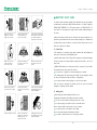
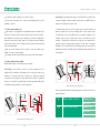
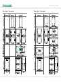
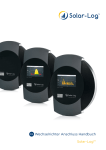
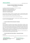
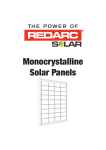
Phono Solar Technology Co., Ltd.
PHONO SOLAR TECHNOLOGY CO., LTD.
Add: No. 1 Xinghuo Rd., Nanjing Hi-tech Zone, Nanjing, China
Tel: +86 25 5863 8000
Fax: +86 25 5863 8009
E-mail: [email protected]
Website: www.phonosolar.com
Photovoltaic Module
Installation Manual (IEC)
Version: IEC 2012-01
Copyright © PHONO SOLAR, 2012
CONTENTS
1. IMPORTANT SAFETY GUIDE
2. PRODUCT IDENTIFICATION
3. MECHANICAL INSTALLATION
4. ELECTRICAL INSTALLATION
5. MAINTENANCE
6. DISCLAIMER OF LIABILITY
Stability / Reliability / Creativity
1 IMPORTANT SAFETY GUIDE
Module (IEC)
RatedPower
Tolerance
RatedPowerVoltage
Open iC
rcuit
Tolerance
RatedPowerVoltage
RatedPower
National
Power
This manual contains information regarding product identification and the safe installation
Module (IEC)
RatedPower
Tolerance
RatedPowerVoltage
Open iC
rcuit
Tolerance
RatedPowerVoltage
RatedPower
National
Power
and maintenance of photovoltaic modules (hereafter referred to as “module”) supplied by
PHONO SOLAR TECHNOLOGY CO., LTD. (hereafter referred to as “PHONO SOLAR”).
The
term “module” can be interpreted as a single module or multiple modules depending on
DO NOT use mirrors or
magnifiers to concentrate
sunlight onto the module.
DO NOT paint the module
or attach anything on to
the back of the module.
DO NOT attempt to disassemble
the modules, and do not remove
any attached nameplates or
components from the module.
the context.
Installers must already be familiar with the mechanical and electrical requirements for a
photovoltaic system. Installers must also read this manual carefully prior to installation. We
recommend that you keep this manual in a safe place for future reference and in case of
future sale or disposal of the module.
1.1 General Safety
The installation of a photovoltaic system requires specialized skills and knowledge and
must only be carried out by licensed/qualified persons.
Module (IEC)
RatedPower
Tolerance
RatedPowerVoltage
Open iC
rcuit
Tolerance
RatedPowerVoltage
RatedPower
National
Power
Installers should assume all risks of injury and do everything to avoid potential damages
DO NOT lift or move the
module by holding the
junction box or cable.
DO NOT place anything on
the module or press on the
module surface.
Toleranc
e
R t dP
DO NOT drop the module or
allow objects to fall on the
module.
and risks that might occur during installation, including but not limited to, the risks of
electric shock.
PHONO SOLAR modules do not need special cables for connection. All of the modules
have permanent junction boxes, cables and connectors.
Do not use mirrors or magnifiers to concentrate sunlight onto the modules.
Module (IEC)
Rated
t Power
To
Tolerance
RatedPowerVoltage
Open iC
rcuit
Tolerance
RatedPowerVoltage
RatedPower
National
Power
The modules generate DC electrical energy from sunlight. They are designed for outdoor
use and can be mounted onto frames on rooftops or in the ground etc.
Do not paint the module or attach anything on to the back of the module.
Do not attempt to disassemble the modules, and do not remove any attached
DO NOT expose the back of
the module to direct sunlight.
Do NOT install or handle
module in wet or strong windy
conditions.
Do NOT wear metal ornaments
while handling the module or
during the installation.
nameplates or components from the modules.
1.2 Handling safety
When handling the module insulated gloves must be worn.
Inappropriate transportation and installation may break the module.
Do not lift or move the module by holding the junction box or cable.
Do not place anything on the module or press on the module surface.
Do not drop the module or allow objects to fall on the module.
Do not expose the back of the module to direct sunlight.
DO NOT drill holes in the frame.
DO NOT use module near
equipment or in places where
flammable gases may be
generated or collected.
Insulated gloves must be worn
while handling the module and
during the installation.
Do not wear metal ornaments while handling the module.
Do not install or handle modules in wet or strong windy conditions.
01
Stability / Reliability / Creativity
1.4 Fire Safety
1.3 Installation safety
Local, regional and state laws and regulations must be adhered to while installing a
photovoltaic system. For example, any necessary licenses must be obtained prior to the
Consult your local authority for guidelines and requirements for building or structural fire
safety.
installation commencing. Regulations around vehicles and ships must also be observed
during the installation.
Roof constructions and installations may affect the fire safety of a building; an improper
installation may create a hazard in the event of a fire.
Observe all safety rules for the other system components, including the cables,
Use components such as ground fault circuit breakers and fuses as required by the local authorities.
connectors, charging controllers, inverter and storage battery etc.
Do not use the modules near a location where flammable gases are either generated or collected.
Do not place the modules near a location where flammable gases are either generated
or collected.
The modules have been rated Fire Class C, and are suitable for mounting onto a
Class A roof.
Insulated gloves must be worn during the installation.
Do not wear metal ornaments during the installation.
Do not drill holes in the frame.
Under normal conditions, a module is likely to produce more current and/or voltage
than reported under Standard Test Conditions (STC). Accordingly, the values of ISC and VOC
marked on the module nameplate should be multiplied by a factor when determining the
component voltage ratings, conductor current ratings, fuse sizes, and the size of controllers
connected to the photovoltaic system. The exact factor value should be suggested by a
licensed/qualified person.
The connecting ends with electricity may cause fire, spark or lethal shocks even when
the modules are not connected.
Electricity can be generated when the modules are exposed to sunlight, even if they are
not connected. It is dangerous to touch 30V DC or higher, so never open the electrical
connectors or unplug the electrical connectors while the circuit is under load, and do
not touch the end with electricity during installations, when the modules are exposed to
sunlight.
Children should be kept away from the photovoltaic system.
In order to prevent current and voltage generation during installation an opaque board
can be used to cover the modules.
Only use licensed/qualified insulated tools.
The frame of the modules must be grounded according to local, regional and state
safety and electrical standards. A recommended connector or equivalent must be used for
the grounding cable. The grounding cable must be appropriately fastened to the module
2 PRODUCT IDENTIFICATION
On the back of each module there are 2 labels that provide the following information:
Nameplate: Describes the product type, rated power, rated current, rated voltage, open
circuit voltage, short circuit current, all as measured under STC; weight, dimensions etc.;
the maximum system voltage of 1000V DC.
Warning: The value of Voc times the number of modules in series should not be bigger than the maximum system voltage marked in the nameplate.
Barcode: This is used to identify each module. Each module has a unique and traceable
serial number in the form of barcode. The barcode of each PHONO SOLAR module has
15 letter/digits.
Warning: Do not remove the nameplate or barcode. The PHONO SOLAR product
warranty will be void if either the module nameplate or barcode is removed.
3 MECHANICAL INSTALLATION
(Note: All instructions hereafter are for reference only. A licensed/qualified person or
installer must be responsible for the design, installation, mechanical load calculation
and security of the photovoltaic system.)
3.1
Select suitable locations for installation
Select a suitable location for installing the modules.
PHONO SOLAR recommends that to achieve the best performance the modules
frame.
Only Balance of System (BOS) in conformity to local, regional, state safety electricity
should face south in northern latitudes and north in southern latitudes. The exact tilt
standards and photovoltaic system such as connectors, cables and frames can be used,
angle and orientation of mounted modules should be recommended by a licensed/
avoiding affect on the module performance and/or damage it.
qualified installer.
02
03
Stability / Reliability / Creativity
The modules should be completely free of shade at all times.
Clamp fitting: Using suitable module clamps on the LONG side of the module frame
Do not place the modules near a location where flammable gases are either
to mount the modules is “portrait orientation” mode, while on the SHORT side of the
generated or collected.
module frame is “landscape orientation” mode.
3.2
The module clamps should not come into contact with the front glass and must not
Select suitable mounting rails
Please observe the safety regulations and installation instructions included with the
mounting rail. If necessary please contact the supplier directly for further information.
deform the module frame. Avoid any shadowing effects from the module clamps.
The module frame can not be modified under any circumstances. Regardless of the
The modules must be safely set onto the mounting rail. The whole rail supporting the
orientation chosen, at least 4 clamps must be used on each module. For portrait
photovoltaic system must be strong enough to resist potential mechanical pressures
orientation, 2 clamps should be attached to the long sides of the module and for
caused either by wind or snow, in accordance with local, regional and state safety (and
landscape orientation 2 clamps should be attached to the short sides of the module.
other associated) standards.
Depending on the local wind and snow loads, additional clamps may be required. The
Make sure that the mounting rail will not deform or affect the modules when it
applied torque should be about 8Nm. Please find detailed mounting information in the
below illustration:
expands as a result of thermal expansion.
The mounting rail must be made of durable, anti-corrosive and UV-resistant materials.
3.3
Select suitable mounting methods
Module Frame
Clamp
PHONO SOLAR modules can be mounted using two methods:
Screw Fitting: Use corrosion-proof screws in the existing installing holes in the
module frame. Each module has 8 mounting holes for securing the module on the
mounting rail. The module frame must be attached to a mounting rail using M8
corrosion-proof screws together with spring washers and flat washers in symmetrical
Mounting Rail
locations on the module. The applied torque should be approximately 8Nm. Please
find detailed mounting information in the below illustration:
M8 Screw
Module installed using Clamp Fitting method
Select the appropriate installation method depending on the load (see below for more
Mounting Rail
detailed information).
Module Frame
M8 Bolt
F Type
Module Frame
Mounting Rail
M8 Screw
Split Washer
M8 Nut
Flat Washer
1580mm × 808mm × 35/45mm
ONYX Series
U Type
DIAMOND Series
1640mm × 992mm × 45mm
ONYX Series
INTELLIGENT Series
Module installed using Screw Fitting method
04
DIAMOND Series
05
Stability / Reliability / Creativity
Phono Solar U Type module
Phono Solar F Type module
06
07
Stability / Reliability / Creativity
Warning: Do not attempt to drill holes in the module frame or in the glass surface of
4.7
the module. Any such modifications will void the PHONO SOLAR product warranty.
maximum voltage of the system.
4.8
3.4
When installing a module on a pole ensure that the pole and mounting rail can
The rated voltage of the cable chosen must be appropriate to the overall
The module frame must be grounded according to local, regional and state
safety and electrical standards. Ensure that a recommended connector or equivalent
withstand anticipated local winds. The pole must be installed on a hard base.
is used for the grounding cable. The grounding cable must be properly fastened to
3.5
the module frame.
Ensure that the installation height is such that the lowest modules will not be
covered by accumulated snow or shaded by the surroundings.
3.6
Ensure that there is adequate ventilation under the modules, conforming to local,
regional and state standards and regulations.
3.7
A minimum distance of 10cm, between the roof plane and the frame of the
In order to ensure optimum module performance, PHONO SOLAR recommends the
following:
module is generally recommended.
3.8
5 MAINTENANCE
Observe the linear thermal expansion of the module frames. A minimum distance
of 1cm between two modules is generally recommended.
5.1
If necessary, the glass front of the module can be cleaned with water and a
soft sponge or cloth. A mild, non-abrasive detergent can be used to remove more
4 ELECTRICAL INSTALLATION
(Note:
All instructions hereafter are for reference only. A licensed/qualified
person or installer must be responsible for the design, installation, mechanical
stubborn stains.
5.2
Check the electrical and mechanical connections periodically and make sure they
are clean, safe, complete and secure.
5.3
In the event of a problem, consult with a licensed/qualified person.
load calculation and security of the photovoltaic system.)
4.1
Any hardware used must be compatible with the mounting material to avoid
6 DISCLAIMER OF LIABILITY
galvanic corrosion.
Since it is impossible for PHONO SOLAR to control installation, operation, application
4.2
and maintenance of the photovoltaic system according to this instruction, PHONO
Only use connectors that are designed for photovoltaic systems and that match
PHONO SOLAR modules.
SOLAR does not accept responsibility and expressly disclaims liability for any loss,
4.3
damage, or expense arising out of or in any way connected with such installation,
When working with the connectors only use tools as recommended by the
connector manufacturer.
4.4
operation, use or maintenance.
PHONO SOLAR recommends that the same type of modules are connected
together in order to avoid any system power loss.
PHONO SOLAR will not take any responsibilities for any possible violation of patent
4.5
rights and third party rights that are related to application of the solar energy system.
The maximum number of series connected modules depends on system design,
the type of inverter used and environmental conditions.
4.6
No permission of patents is given through implication.
Select insulated cables that are able to resist to ultraviolet radiation and
extreme weather conditions.
The information of this instruction is from knowledge and experiences of PHONO
08
09
SOLAR, and so it is reliable. However, the instructions and suggestions of this
instruction do not make an external or internal of guarantee. PHONO SOLAR reserves
the right to revise this instruction, products and all the information about products
without prior notification to customers.
10