1
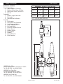
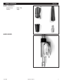
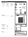
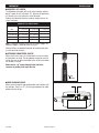
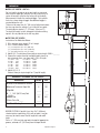
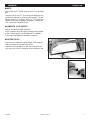
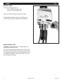
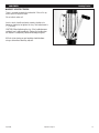
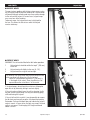
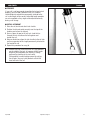
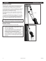
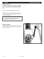
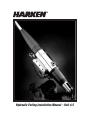
Hydraulic Furling Installation Manual – Unit 4.5 GENERAL SPECIFICATIONS ■ TABLE OF CONTENTS General Specifications 2 Table of Contents, Dimensions 3 Stainless Surface, Hoses & Fittings 4 Drain System, Valves, Pressure, Oil 5 Part List Preparation 7 Headstay Length, Connectors 8 Foil Length 9 Connector and Foil Quantity Assembly 10 Foil Assembly 12 Stay to Lower Unit Connection 14 Lower Toggle and Cowling 15 Torque Tube Alignment 16 Foil Length Check 17 Raise Unit; Gear Box Pressure 18 Hoses, Oil Level 19 Headstay Tension 20 Halyard Wraps 21 Pendants 22 Halyard Restrainer 23 Before Operation Table of Contents DIMENSIONS - *Unit with 13/8” (34.9 mm) clevis A B C D E 48 / ” 1235 mm 32 / ” 826 mm 28 / ” 718 mm 14 / ” 378 mm 157/8” 403 mm F G H I J 17 / ” 454 mm 8/ ” 216 mm 9/” 244 mm 14” 356 mm 181/8” 460 mm 5 8 7 8 12 12 14 5 8 7 8 *Subtract 5/16” (8 mm) for 11/4” (31.8 mm) clevis. Add 5/8” (16 mm) for 19/16” (39.7 mm) clevis (A to F only). HARKEN - Main Office 1251 E. Wisconsin Avenue, Pewaukee WI 53072 Tel: 262-691-3320, Fax: 262-691-3008 HARKEN - East (Trade Only) One Mill Street, Newport RI 02840 Tel: 401-849-8278, Fax: 401-841-5070 HARKEN - West (Trade Only) Tel: 619-475-0712, Fax: 619-475-0816 2 Hydraulic Furling 4.5 December 2002 GENERAL SPECIFICATIONS Unit 4.5 ■ STAINLESS STEEL SURFACE Be careful not to scratch the stainless steel surfaces of the lower unit. Lay the unit on terry cloth or other soft material while assembling. The hydraulic unit is polished stainless and does not have chrome plating. (Chrome was eliminated due to occasional discoloration.) This surface can be polished using standard stainless steel polishes to maintain its appearance. ■ PORT SIDE UP Keep the port side of the unit facing up when sitting on its side. If the unit will sit for a long period of time, or is stored or shipped, keep the port side of the lower unit facing up. This will prevent gear oil from leaking out of a pressure relief valve. TIP: When the port side is up, the sideplate with the winch handle socket will be facing down. If a small amount of gear oil does leak out of the valve during shipping or installation, it will drip out of the bottom of the unit when up in sailing position. Use a rag to catch this leakage. ■ HOSES Hoses are not supplied with furler. Use SAE 100 R1 or R2 hoses. Sizes depend on the distance that the hoses will run and the power source. For shorter runs use: Two Drive Hoses: -6 (3/8” ID) One Drain Hose: -4 (1/4” ID) Contact Harken for further hose size recommendations. ■ HOSE END FITTINGS Hose fittings are not supplied with furler. All fittings must be stainless steel. Standard attachment method uses female hose end fittings. Furling unit end fittings have JIC 37° flair fittings. Note: Do not use locking solution or tape on connections. Hose end fittings sizes: Drive fittings - JIC 9/16-18 female swivel Drain fittings - JIC 7/16-20 female swivel ■ ALTERNATE FITTING METHOD Remove furling unit end fittings. Use SAE straight thread O-ring male hose end fittings: Drive fitting - 9/16-18 Drain fitting - 7/16-20 April 2000 Hydraulic Furling 4.5 3 GENERAL SPECIFICATIONS Unit 4.5 ■ DRAIN SYSTEM Besides the main hoses for forward and reverse, a fitting for a drain hose is included. The drain hose must be lead to the main reservoir in the power unit. Power Requirements Size Recommended Flow Rate Rotation at No Load 4.5 7 GPM (26.7 L/min.) 32 RPM The unit will work with any Harken hydraulic power pack. Best performance will be with the hydraulic 6 or 8 system. See performance charts. ■ Valves On Power Unit Furler can be used with open or closed center, 4-way, 3-position control valves. ■ MAXIMUM OPERATION PRESSURE Set relief valve on power plant at 140 Bar or 2000 PSI. Harken power packs ship with valves set at 140 Bar. ■ OIL SPECIFICATIONS Gear box oil - AGMA8, 90 weight gear oil 24 ounce (680 g) capacity Note: The gear box is filled with oil at the factory. Under normal conditions there is no need to change the gear box oil. Hydraulic fluid is a petroleum based oil, ISO viscosity grade 46, anti-corrosion, anti-foam, anti-oxidant, anti-rust, anti-wear additives. Fluid examples: Exxon Nuto, Shell Tellus, BP Energol HLP WARNING: The only parts of the furler to be disassembled by the installer are: Torque Tube, Lower Cowling. All other work should be performed by factory authorized personnel. Note: Some fluid may drip from the unit during shipping. This is normal and should go away once the unit is in its sailing position. All units are tested before leaving the factory. Units are shipped port side facing up. Make sure unit is shipped or stored port side up. If it’s not, gear oil will leak out of the pressure relief valve. 4 Hydraulic Furling 4.5 April 2000 GENERAL SPECIFICATIONS ■ MAIN COMPONENTS Halyard Swivel Cowling Parts List Torque Tube Toggle ■ MAIN HOUSING April 2000 Hydraulic Furling 4.5 5 GENERAL SPECIFICATIONS Parts List ■ MISCELLANEOUS PARTS Red Loctite Foil Screws Blue Loctite Torque Tube Screws Cross Pin Clevis Pin Circlip Tack Shackle Foil Wedges 6mm, 8mm Allen Wrench Cotter Pin Feeder ■ RIGGER PARTS Trim Cap Connectors Long Bottom Connector ■ TERMINAL-WIRE Nosepiece Main Body Wedge Former Drive Pin ■ TERMINAL-ROD Nosepiece Drive Pin ■ FOILS Bottom Foil Foils 6 Collar Hydraulic Furling 4.5 April 2000 PREPARATION Headstay Length ■ HEADSTAY CUT LENGTH The following cut lengths will result in the headstay adjuster being 1/2 open. At this cut length, 31/2” (89 mm) of adjustment will remain in the stay adjuster in either direction. Subtract the following from the headstay length and cut the stay at that point. HEADSTAY CUT LENGTH CHART Headstay Size Clevis Pin Size 11/4” (31.80 mm) 13/8” (34.90 mm) 19/16” (39.70 mm) -76 (17.9 mm rod) 317/8” (810 mm) -91 (19.5 mm rod) 317/8” (810 mm) 321/4” (819 mm) -115 (22.2mm rod) 25 mm wire 323/8” (822 mm) 327/8” (835 mm) 333/8” (848 mm) 337/8” (860 mm) Note: The Harken hydraulic furler has an integral toggle. No additional toggle is required below the furler. Contact Harken to coordinate position of headstay rod splices with connector location. ■ STRINGING CONNECTORS ON STAY Make sure the trim cap is at the top and the correct number of connectors are used. The long bottom connector must be slid on the wire or rod so the feeder holes will be matched to the window in the foil. Make sure the “up” arrow stamped on the front of the connector is pointing to the top of the stay. Up Arrow ■ ROD COLDHEAD HEIGHT Make sure the length of rod coldhead does not interfere with the drive pin. There is a .40” (10 mm) space between the collet bottom and the roll pin. April 2000 Hydraulic Furling 4.5 7 PREPARATION Foil Length ■ FOIL CUT LENGTH - UNIT 4.5 Foil cut length is based on pin-to-pin length as measured from center of upper pin (attaches the stay to the mast) to center of lower pin (attaches the furling unit to the boat). Measurement includes the masthead toggle. The hydraulic furler has a lower integral toggle. No additional toggle is required below the unit. There must be more than 31/2” (89 mm) of adjustment above the trim cap when the adjuster is set to the half way point. The total adjuster stroke is 7” (178 mm). (See inset 1) To check foil length, lay foils alongside stay before cutting top foil. Set stay adjuster to the half way point. ■ TOP FOIL CUT LENGTH Instructions For Worksheet Below: 1 Fill in total pin-to-pin length. Fill in A length. 2 Fill in F from numbers below: 11/4” (31.8 mm) Clevis pin = 43” (1092 mm) 13/8” (34.9 mm) Clevis pin = 431/4” (1099 mm) 19/16” (39.7 mm) Clevis pin = 44” (1118 mm) 3 4 Add A, B, E, F and subtract from total pin-to-pin length. SUM = _______ Choose the number from foil multiplier below closest to but not greater than, sum from step 3. Fill in D length. *5 x 144 = 6 x 144 = 7 x 144 = 8 x 144 = 9 x 144 = 10 x 144 = 720 864 1008 1152 1296 1440 **5 x 3657.5 = 6 x 3657.5 = 7 x 3657.5 = 8 x 3657.5 = 9 x 3657.5 = 10 x 3657.5 = 18288 21945 25603 29260 32918 36575 5 Add A, B, D, E, F. Subtract from pin-to-pin length for C (top foil length). WORKSHEET: DETERMINE TOP FOIL LENGTH DIMENSIONS INCHES MM A Center of PIN to Bottom of Terminal _____ _____ 6 152 C Top Foil _____ _____ D __?__ 144” (3657.5 mm) Foils *_____ **____ B Bottom of Terminal to Top of Foil (Quantity) E Bottom Foil 24 F Clevis Pin to Foil_____ _____ Total Pin-to-Pin Length _____ 610 _____ BEFORE CUTTING: If top foil is less than 195/8” (498 mm), shorten top trim cap bushing. If this will not work, it may be necessary to shorten one of the full length foils and redrill holes. Drill a 17/32” (13.2 mm) trim cap hole in the top foil, opposite the grooves, centered at 4” (101.5 mm) from the top of the foil. 8 Hydraulic Furling 4.5 April 2000 PREPARATION Cutting Top Foil ■ NOTES Unit 4.5 foils are 12’ (3.658 m) long. Unit 4.5 has no feeder gap. There must be at least 31/2” (89 mm) of wire above the trim cap when the adjuster is set to the half way point. The total adjuster stroke is 7” (178 mm). Drill a 17/32” (13.2 mm) trim cap hole in the top foil, opposite the grooves, centered at 4” (101.5 mm) from the top of the foil. ■ CONNECTOR & FOIL QUANTITY Refer to the Top Foil Length Worksheet. Unit 4.5 requires one fewer regular connector than number of foils. (Count top foil, but not bottom foil.) In addition, a trim cap and long bottom connector is required. ■ CUTTING TOP FOIL Once you have checked the top foil length, cut the top foil. Deburr and clean all shavings from the foil. Important: Failure to deburr or clean the inside of the foil may cause it to seize to a connector when installing on rod. April 2000 Hydraulic Furling 4.5 9 ASSEMBLY Foils ■ ASSEMBLE FOIL Make sure you have drilled a hole in the top foil so it lines up with the hole tapped in the trim cap. Slide top foil to top of stay, screw holes towards the bottom. TIP: When working with rod, tape lower connectors in place or use a pusher wire longer than foil to hold connectors. Coat the trim cap top bushing with red Loctite. Place a wedge in the indentation and insert into the top foil. Coat a foil screw with red Loctite. Thread into connector hole. Slide first connector to the top of the stay. Coat half of the connector and the indentation with red Loctite. Place a plastic connector wedge in the indentation closest to the top foil. 10 Hydraulic Furling 4.5 April 2000 ASSEMBLY Foils Coat three foil screws with red Loctite. Screw them into the connector until tight. Continue assembly. Slide halyard swivel onto foil, tall end up. Install feeder screws toward bottom, using red Loctite on screws. Slide torque tube onto foils. April 2000 Hydraulic Furling 4.5 11 ASSEMBLY Attach Stay - Rod ■ ATTACHING STAY TO LOWER UNIT - ROD Use a winch handle to crank the terminal completely out of the lower unit. Make sure halyard swivel and torque tube have been slipped on the foils. Slip the rod adapter main body onto the rod. Sandwich the nosepiece over the rod and insert into the main body, narrow end first. Jiggle the main body or use a small screwdriver to push the nosepiece completely into main body. Put several drops of the blue Loctite on the large threads of the stud. Thread the stud into the main body until the slot aligns neatly with the hole in the main body. TIP: Sight through the pin hole to find the optimum thread engagement. Make sure the stud is threaded far enough so the pin is securely seated in the slot, yet not threaded too far to block the pin. Hammer the pin into the main body. Put blue Loctite on pin. Clean excess Loctite from the terminal body using special care to insure that no Loctite is present on the lower threaded stud. 12 Hydraulic Furling 4.5 April 2000 ASSEMBLY Attach Stay - Wire ■ ATTACHING STAY TO LOWER UNIT — WIRE Assemble wire terminal per Sta-lok instructions. Note: To prevent seizing nosepiece threads when forming the wires, put red Loctite on the threads to lubricate them. Open terminal up for inspection. Put sealant inside terminal. Use a winch handle to crank the terminal completely out of the lower unit. Apply red Loctite to the stud or the socket of wire terminal. Clean excess Loctite off the stud below the terminal. Thread the hydraulic unit onto the Sta-Lok terminal and wire. Protect stainless steel housing and sideplates from scratching when rotating unit. Use saw horses that are padded and have terry cloth covering. Put red Loctite on the pin and drive it into place. Clean excess Loctite from the terminal body using special care to insure that no Loctite is present on the lower threaded stud. April 2000 Hydraulic Furling 4.5 13 ASSEMBLY Lower Toggle and Cowling ■ INSTALL LOWER TOGGLE AND COWLING The integral toggle can be installed so the clevis pin runs either fore/aft or athwartships. Choose the correct hole in the base and use the cross pin to secure the lower toggle so clevis pin runs the correct direction. Slip the cowling in place. Secure using the circlip provided. 14 Hydraulic Furling 4.5 April 2000 ASSEMBLY Torque Tube ■ INSTALL TORQUE TUBE Secure the torque tube to the lower unit using the six cap screws provided. Use blue Loctite on the screws. TIP: Insert all six screws BEFORE tightening. ■ RAISE FOILS Push the foils to the correct height and use an allen wrench to secure the torque tube to the foils using the three screws provided. Use blue Loctite on the screws. April 2000 Hydraulic Furling 4.5 15 ASSEMBLY Foil Length ■ CHECK FOIL LENGTH Once the foils and lower unit are assembled, use a winch handle to close the stay adjuster. Turn the handle in a clockwise direction. Check the clearance between the top of the foil and top terminal. TIP: Check clearance when the unit is on the ground, before raising the headstay into position. WARNING: It is critical to have clearance between the top foil and the top rigging fitting when the stay adjuster is in the fully closed position. If the fittings touch, the unit will jam or in the case of a Sta-Lok fitting, the terminal may become unscrewed. This could cause catastrophic failure to the spar and a life threatening situation. It is the responsibility of the rigger to check clearance. 16 Hydraulic Furling 4.5 April 2000 ASSEMBLY Raise Furling • Gearbox Pressure ■ RAISE FURLING UNIT ON MAST CAUTION: To prevent damage to the stay adjuster, make sure the torque tube is secured to the foils and the lower unit before moving the unit. If the unit will sit for a long time, make sure the port side of the lower unit is facing up. TIP: The sideplate with the winch handle socket will be facing down. Once you have closed the stay adjuster to confirm there is clearance above the foils, open the adjuster all the way. Turn the stay adjuster counter-clockwise to open the adjuster completely. This makes it easier to connect the stay to the boat. TIP: Cover unit with terry cloth & padding to protect stainless finish. ■ GEARBOX PRESSURE It is possible that pressure has built up in the gear box during shipping. Once the unit is in sailing position, relieve pressure by using a 6 mm allen wrench to open the filler valve on top of the lower unit. Install the cap so it is wrist tight (20 foot pounds). April 2000 Hydraulic Furling 4.5 17 ASSEMBLY Hoses ■ INSTALL HOSES Use hose end fittings which are: Drive: JIC 9/16-18 female swivel Drain: JIC 7/16-20 female swivel Do not use locking solution or tape on connections. Alternate Method: Remove furling unit end fittings and use SAE straight thread O-ring male hose end fittings. ■ CHECK GEAR OIL LEVEL WARNING: Do not overfill gear oil. Overfilling will cause leaking from the breather valve. Oil can be checked from the top of the case. Insert a small metal stick into the filler hole at the top of the gear housing. Oil should be at the bottom of the gears. When the unit is in the angled sailing position, the oil level will be 2” (51 mm) from the top of the housing. 18 Hydraulic Furling 4.5 April 2000 ADJUSTMENTS Headstay Tension ■ ADJUST HEADSTAY TENSION There is no need to unlock the turnbuckle. If the sail is up, make sure the halyard is loose. Do not adjust under sail. Insert a winch handle and rotate counter clockwise to loosen or clockwise to tighten the stay. Total adjustment is 7” (178 mm). CAUTION: When tightening the stay, if the handle becomes suddenly hard, stop immediately. Forcing the handle when the adjuster is completely closed will damage the gears. All final rig tensioning or spar bending should be done using a conventional backstay adjuster. April 2000 Hydraulic Furling 4.5 19 ADJUSTMENTS Halyard Wraps ■ HALYARD WRAPS The most serious problem with furling systems occurs when the jib halyard wraps around the headstay foil. Halyard wraps will prevent furling or unfurling and may cause serious damage to the unit and the halyard. In severe cases, halyard wraps may cause loss of the headstay. To prevent wraps, the halyard must exert a slight pull to the rear. This allows the foils to turn while the halyard remains stationary. ■ PREVENT WRAPS WARNING: The sail must be fitted to the foils before operation. 1 Halyard swivel should be within the top 6” (150 mm) of the foil. 2 Halyard must pull slightly to the rear (8 - 10°). 3 Halyard must be snug, but not too tight. TIP: With the sail raised, walk away from the boat and look at the masthead with binoculars. Use the halyard swivel as a measurement reference. 6” (150 mm) is 1/3 the length of the swivel. There should be less foil exposed above the swivel than 1/3 of the swivel. 8 - 10° If a halyard wraps, do not force the unit to turn. Attempt to open the sail by alternately furling in and out slightly. If the sail can be unfurled, lower the sail by releasing the jib halyard. Severe halyard wraps can only be cleared by going aloft and freeing the halyard. If the sail will not furl or unfurl, it may be possible to remove the jib sheets and manually wrap the sail around the headstay. Remember: Testing at the dock does not indicate the halyard angle is correct. In wave action, the foils may wrap if the lead angle is not correct. The diverging 8-10°angle mentioned above is critical. 20 Hydraulic Furling 4.5 April 2000 ADJUSTMENTS Pendants ■ PENDANTS If your sail is not long enough to position the halyard swivel properly, you must add a pendant to the sail. Pendants should be plastic coated wire permanently attached to the sail so the height will be correct. Adjustable length pendants are not acceptable as they might not be adjusted correctly during a sail change. ■ INSTALL A PENDANT 1 Raise the sail, but do not attach tack shackle. 2 Position the halyard swivel correctly near the top of the headstay and secure the halyard. 3 Secure a piece of rope to the sail tack. Lead the line through the tack shackle on the furling drum and tension the sail. 4 Measure the distance from the tack shackle to the sail tack and have a pendant of this length permanently attached to the head of the sail. 5 Repeat this procedure for every jib. TIP: Pendants are used at the head of the sail. Short pendants may be added at the tack to improve visibility under the genoa, but remember that visibility is already improved by shackling to the tack swivel. Tack pendants increase heeling moment by raising the sail plan. You may install pendants at both the head and tack of the sail. April 2000 Hydraulic Furling 4.5 21 ADJUSTMENTS Halyard Restrainer • Tension ■ HALYARD RESTRAINER To prevent wraps, the jib halyard must pull slight to the rear. On some boats the halyard sheaves are located too close to the headstay and a halyard restrainer must be used. Use halyard restrainers only when required by the masthead geometry. Restrainers tend to limit sail luff length and may cause problems if not properly installed. Mount the restrainer as high as possible on the face of the mast. Position the restrainer so the foils will not hit it when under load. The restrainer should deflect the halyard 8-10°. If the angle is more than 10°, you may experience difficulty in tensioning the sail luff, friction in furling and possible damage to the foils. To decrease deflection angles, shorten the luff of the sail. 8 - 10° TIP: Boats used in charter service should consider using a halyard restrainer, regardless of masthead geometry. ■ HALYARD TENSION The jib halyard should be firm, but not too tight. TIP: The luff foil system supports the sail along its entire length so halyard tension is required only to shape sails, not to support them. Use only enough halyard tension to remove some wrinkles along the luff. Do not tension the halyard enough to cause vertical wrinkles in the luff. Use halyard tension to adjust draft position of the sail to suit sailing conditions. Your halyard should be firm but not tight. If in doubt, release halyard tension. To protect the sail, ease the halyard when the boat is not in use. 22 Hydraulic Furling 4.5 April 2000 ADJUSTMENTS Before Operation • Manual Operation ■ BEFORE OPERATION WARNING: Before operating, consult pages on halyard lead angle. If sails are changed, make sure halyard lead angle is correct. A halyard wrap cannot be tolerated on a hydraulic furler. Make sure to ease sheets before operating the system. CAUTION: Do not use the hydraulic furler to sheet the sail. The direction of furling is up to the individual. Make sure suncover is rolled correctly. TIP: Label the buttons “in” and “out” and be consistent in their use when rolling and unrolling the sail. This way, it will be possible to furl in the desired direction at night when the sail is hard to see. ■ MANUAL OPERATION To furl or unfurl the unit manually, push the lever to manual and insert a winch handle in the starboard socket. Rotate to move the sail in or out. April 2000 Hydraulic Furling 4.5 23 Corporate Headquarters 1251 East Wisconsin Avenue, Pewaukee, Wisconsin 53072 USA Telephone: (262) 691-3320 • Fax: (262) 691-3008 • Cable: Harken Pewaukee Web: www.harken.com • Online Catalog: www.harkenstore.com Email: [email protected] Harken France ZA. Port des Minimes, BP 3064, 17032 - La Rochelle Cedex 1, France Telephone: (33) 05.46.44.51.20 • Fax: (33) 05.46.44.25.70 Web: www.harken.fr Email: [email protected] Harken Italy S.P.A. Via Della Cerca, 12/14, 22070 Lurago Marinone, Como, Italy Telephone: (39) 031.3523511 • Fax: (39) 031.3520031 Web: www.harken.it Email: [email protected] Harken UK Ltd. Bearing House, Ampress Lane Lymington, Hampshire S041 8LW, England Telephone: (44) 01590-689122 • Fax: (44) 01590-610274 Web: www.harken.co.uk Email: [email protected] Harken Poland ul. Lisa Kuli 4 lok.1, 01-512 Warszawa, Polska Telephone: 022 561 93 93 • Fax: 022 839 22 75 Web: www.harken.com Email: [email protected] Harken Sweden Mjölkekilsgatan 6, Box 64 S-440 30 Marstrand, Sweden Telephone: (46) 303-618 75 • Fax: (46) 303-618 76 Web: www.harken.se Email: [email protected] Harken Adriatik d.o.o. Obala 107 6320 Portoroz, Slovenia Telephone/Fax: 5-6774122 Web: www.harken.si Email: [email protected] Harken Australia, Pty, Ltd. 1B Green Street Brookvale, N.S.W. 2100, Australia Telephone: (61) 2-8978-8666 • Fax: (61) 2-8978-8667 Web: www.harken.com.au Email: info.harken.com.au Harken New Zealand, Ltd. 30-36 Fanshawe Street Auckland 1001, New Zealand Telephone: (64) 9-303-3744 • Fax: (64) 9-307-7987 Web: www.harken.co.nz Email: [email protected] Please visit: http://www.harken.com/dealers/dealers.php for an up-to-date list of Harken dealers and distributors Printed in USA 4905/11-06