1
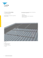
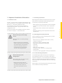
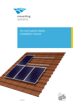
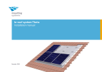
Tau+ On-Roof System
Installation Manual
810-0107
Contents
Tau + Installation Manual
Tau + — The innovative
trapezoidal solution with a plus
1.Introduction
1.1. Short Description
1.2. About These Instructions
1.3.Warnings
1.4.Safety
2
2
2
3
3
2.
Technical Description
2.1. System Overview
2.2.Components
2.3. Technical Data
4
4
5
6
3.
3.1.
3.2.
3.3.
3.4.
Important Mounting Information
Conditions of Use
Mounting Preparations
Mounting Aids and Required Tools
On the Mounting Descriptions
7
7
7
7
7
4.
Planning the Module Area
for a Portrait Layout of the Modules
8
5.
Mounting Profile Rails
for Portrait Mounting of the Modules
5.1. Placing the EPDMs
5.2. Positioning and Alignment
of the Profile Rails
5.3. Placing the Side Trapezoid Clamp
5.4. Placing the Top Trapezoid Clamp
5.5. Fastening the Profile Rail
5.6. Connecting Profile Rails
5.7. Securing the Profile Rails
From Excessive Slipping
2
Tau+-MA-ENG-1309
10
10
11
12
12
13
14
15
Mounting Modules in portrait orientation
Mounting Clickstones
Fastening the Modules on the Outer Side
Fastening the Modules on the Inner Side
Fastening Additional Module Rows
16
16
18
19
20
7.
Planning the Module Area
for Landscape Mounting of the Modules
21
8.
Mounting of Profile Rails
for Landscape Mounting of the Modules
22
9.
9.1.
9.2.
9.3.
9.4. Mounting Modules Laterally
Mounting Clickstones
Fastening the Modules on the Outer Side
Fastening the Modules on the Inner Side
Fastening Additional Module Rows 24
24
26
28
29
Tau + Installation Manual
6.
6.1.
6.2.
6.3.
6.4.
Contents
1
1
1. Introduction
Tau + Installation Manual
1.1. Short Description
The Tau+ on-roof system is a robust racking system
for the mounting of PV modules on trapezoidal
sheet roofs.
It consists of aluminium support rails and all necessary
small parts for the fastening of the modules on to the
rails as well as for the connection of the components
with each other. The Tau+ allows for both portrait and
landscape installation of the modules.
It is crucial to carefully read these Mounting
Instructions as well as all applicable documents
prior to carrying out any installation, maintenance
or disassembly work. You are provided with all
the information required for the safe and complete
mounting, maintenance and disassembly.
Should you have any questions, please contact
Mounting System GmbH.
User Group
Mounting Systems GmbH’s installation instructions are
intended for the following persons (user group):
1.2. About These Instructions
Content
These instructions describe the installation of the onroof system Tau+ and all system-specific information for
planning, components and safety.
The drawings in the first part of the instructions
show the portrait installation of framed modules. The
landscape version is treated separately from chapter 7
onwards.
Applicable Documents
In addition to this document, the document “Mounting
Instructions for PV Mounting Systems: General Part”
is part of each product delivery. This document
describes the general applicable information for
Mounting Systems’ product range on standardisation,
safety, transport, maintenance, disassembly and
disposal. Both the present Mounting Instructions and
the “Mounting Instructions for PV Mounting Systems:
General Part” are an integral part of the mounting
system Tau+ and must be adhered to for each
installation.
• Skilled personnel
• Instructed personnel
Skilled personnel
Skilled personnel are individuals who, on the basis
of their professional training, are able to execute
installation, maintenance, and disassembly work
appropriately.
Instructed personnel
Instructed personnel are individuals who have been
instructed and taught appropriately regarding the
assigned tasks and the possible risks in the event of
improper conduct. An instructed individual must have
received instructions regarding the required safety
policies, precautions, relevant regulations, accident
prevention regulations, as well as operating conditions
and must have demonstrated his/her competence.
The implemented work must be approved by skilled
personnel.
Orientation Guide
The following visual aids will make installation easier.
Pictograms:
This symbol indicates important information
and useful tips.
i
This symbol indicates tips and tricks to make
processes easier.
2
Introduction
1.4. Safety
The warnings used in these Mounting Instructions
indicate safety-related information. They include:
All generally applicable safety regulations for products
of Mounting System GmbH can be viewed in the
document “Installation Instructions for PV Mounting
Systems: General Part.” Please read this document
carefully and adhere to the instructions - only use
the system for its intended purpose, comply with the
obligations of the building owner and follow both the
general and specific safety instructions.
In addition, in all actions you carry out please observe
the specific safety instructions, which precede the
process steps in the present mounting instructions.
• Warning symbols (pictograms)
• Signal words for the identification of the hazard level
• Information about the type and source of the hazard
• Information about potential consequences in case of
the hazard being disregarded
• Measures for the prevention of hazards and the
prevention of injuries or damage to property.
Tau + Installation Manual
1.3. Warnings
The signal words of the warnings respectively indicate
one of the following hazard levels:
DANGER
WARNING
CAUTION
ATTENTION
Indicates a great and extraordinary
danger, which may result in death
or serious injury if ignored.
Indicates a potentially dangerous
situation, which may result
to serious or medium injury or
damage to the property.
Indicates a potentially dangerous
situation, which may result in
minor injuries or damage to the
property if ignored.
Indicates potential danger,
which can result in damage
to the property.
Introduction
3
2. Technical Description
The design of the individual system components
can vary. This depends on:
2.1. System Overview
• Roof type,
• Type of module,
• Number of modules and configuration
• Local conditions.
Tau+ Installation Manual
In the following, all system components
are described.
a
e
c
d
b
Image 2.1. – 1
a Roof
b Lateral fixing clip
c Module clamp
d Module end clamp
eEPDM
4
Technical Description
2.2. Components
In the following all system components of the Tau+ are
shown, which can be included in the scope of the delivery.
The exact scope of the delivery and the number of individual
components depends on your order.
a
b
c
a Tau+ Rail
Tau+ Installation Manual
b Tau+ Rail for landscape installation,
with pre-mounted EPDM
c Tau+ side fixing clip with AluFix seal
d Tau+ top fixing clip
d
e
f
e Thin sheet-metal screw (5.5x25mm)
f Tau+ Connector
i
g Tau+ Connector with grounding option
h EPDM 80 mm (for top fixing clip)
or 40 mm (for side fixing clip)
g
h
i
i Module clamp
j Module end clamp
k Position lock
j
k
Image 2.2. – 1
Technical Description
5
Tau+ Installation Manual
2.3. Technical Data
Application
Pitched roof – on-roof
Roof cladding
Suitable for most types of roof cladding
Roof slope
Up to 60°
Building height
Up to 20 m
PV modules
Framed
Module orientation
Landscape, portrait
Size of module array
Any size possible
Position of the module array
No special requirements
Distance between roof fixing
points
Up to 2m
Standards
Eurocode 1 – Action on structures
Eurocode 9 – Design of aluminium structures
Supporting profiles
Extruded Aluminium (EN AW 6063 T66)
Hooks, small parts
Stainless steel (V2A)
Colour
Aluminium: plate finish; on request:
Visible components available in back
Warranty
10 Years
1
1
2
1
3
1 Different maximum values may apply, depending on site, building, choice of roof fixations and module type.
Using the Tau+ calculation tool, you can have the exact values for your specific project calculated quickly
and easily.
2 Due to thermal expansion of the material, we recommend an interruption of the array after 12 m.
3 Please find the exact terms in the Mounting Systems GmbH warranty document.
6
Technical Description
3.1 Conditions of Use
The Tau+ on-roof system is designed with different rail
and roof fasteners in accordance with Eurocode 1-DIN
EN 1991-1-1 for various maximum loads.
The suitability of the material must therefore be
verified for each system, e.g. by means of the Tau+
configuration tool.
Please also observe the suitability constraints, which
are listed in Chapter 2.3 “Technical Data”.
3.2. Mounting Preparations
Mounting System GmbH recommends that you inquire
about the local conditions before ordering the Tau+.
In particular, acquaint yourself with:
• Roof condition (e.g. bead distance and bead height),
• The thickness and the material of the trapezoidal
sheet,
• The quality and the condition of the trapezoidal
sheet
• Adequate fastening of the trapezoidal sheet to the
substructure.
3.3. Mounting Aids and Required Tools
Risk of fatal injury from damage
to roof
DANGER
Excessive loads can severely damage
the roof.
• Before mounting and installation,
please make sure that the building
and especially the roof cladding
meet the increased structural
requirements for the PV system
and the mounting operation.
For the installation of the mounting system, you will
require the following tools:
• Allen key 5 mm/ hexagon socket drill bit, 5mm,
• Cordless screwdriver
• Drill bit for cordless screwdriver TX30
• Angle grinder with metal cutting disc
• Chalk line
• Spirit level
• Yard stick / tape measure
• Lifting gear (e.g. aerial lifts, carrying straps)
• Suction lifter
• If required, Spacer gauge (for landscape installation)
3.4. On the Mounting Descriptions
Risk of fatal injury from
falling objects
DANGER
Parts falling from the roof can result
in serious injuries or death.
• Before commencing with the
installation, please ensure that
the material used meets the
structural requirements of the
site.
In the following chapters all steps for the planning
and installation of the Tau+ are listed in the correct
sequence. Chapters 4, 5 and 6 describe the installation
steps for a portrait layout of the modules; chapters 7,
8 and 9 describe the installation steps for a landscape
installation.
Please adhere to the mounting steps listed here and be
sure to follow the safety instructions.
Important Installation Information
7
Tau+ Installation Manual
3. Important Installation Information
Tau + Installation Manual
4.Planning the Module Area
for a Portrait Layout of the Modules
For portrait installation, the profile rails are fastened
to the beads of the trapezoidal sheet by means
of fixing clips. The clips must be mounted with a
defined distance, which depends on the material and
thickness of the trapezoidal sheet, the distance to
the high beads, the position on the roof and the onsite conditions.* The layout is defined by the design
in the configuration tool or by project-related
structural analyses.
Taking the above mentioned points into account,
the fixing clips must be placed in such a way that
they are as close as possible to the module clamps.
Risk of fatal injury from
damage to roof
DANGER
Excessive loads can severely damage
the roof.
• Before mounting and installation,
please make sure that the building
and especially the roof construction
meets the increased structural
requirements resulting from the PV
system and the assembly operation.
When positioning the fixing clips take into
account that:
• The specified dimensions are approximate values
• The dimensions of the trapezoidal sheet and the
high beads define the true horizontal distance.
Risk of fatal injury from
falling objects
DANGER
* Layout required according to local conditions in
accordance with Eurocode 1-DIN EN 1991-1-1/Eurocode
9-DIN EN 1999-1-1.
8
Planning the Module Area for a Portrait Layout of the Modules
Parts falling from the roof can result
in serious injuries or death.
• Before any mounting or installation,
please make sure that the material
used is suitable for the building
structure and meets the structural
requirements applicable on-site.
2
5
Tau + Installation Manual
3
1
4
Image 4. – 1
1 Height of the module field: Number of modules vertically x module length (+ desired clearances)
2 Width of the module field: Number of modules horizontally x (module width + 19 mm) + 41 mm
3
Vertical distance of the rail (in accordance with the clamping points defined by the module manufacturer): Approx. quarter points of the modules = 1/2 x module length
4 Horizontal distance of the fixing clips: According to the plan, depending on the trapezoidal sheet and the structural calculations*
5 Distance between the modules = 17-19 mm
* Layout required according to local conditions in accordance with Eurocode 1-DIN EN 1991-1-1/Eurocode
9-DIN EN 1999-1-1.
Planning the Module Area for a Portrait Layout of the Modules 9
5.Installing Rails for Portrait Layout
of the Modules
Risk of fatal injury from
falling objects
Risk of fatal injury due to falling
DANGER
Falling from the roof can result in
serious injuries or death.
Tau + Installation Manual
• Please wear the statutory
protective equipment.
• Secure yourself against falling.
• Do not perform any work in
strong winds.
DANGER
Parts falling from the roof can result
in serious injuries or death.
• Block off the hazard area on the
ground prior to the mounting work
to prevent falling objects injuring
persons.
• Ensure that no parts can fall off
the roof.
• Please wear the statutory protective
equipment.
• Do not stay in the hazard area.
• Do not perform any work in strong
winds.
• After completion of the installation,
check the racking system and the
modules for a tight fit.
5.1. Placing the EPDMs
Mounting steps:
• Determine the position of the rails on the trapezoidal
sheet taking into account the permissible clamping
points of the PV modules used.
• Mark the position of the EPDMs on each high bead
with the aid of a chalk line.
Image 5.1. – 1
• Stick an EPDM strip onto each high bead on which
the rails rest.
• For the fixation of the rails with side fixing clips ,
EPDM 40x20x1 mm is used; for the top fixing clips,
use EPDM 80x20x1 mm. Make sure that the rail is not
positioned on callottes. The rail position might have
to be adapted accordingly, taking the clamping area
of the modules into account.
Image 5.1. – 2
10
Installing Rails for Portrait Layout of the Modules
5.2. Positioning and Alignment of the Rails
Mounting steps:
• Position the total rail length and perform any
necessary rail cuts.
• Place the rails on the applied EPDMs.
• Align the rails by using a chalk line or spirit level.
i
Note:
Connected rail tracks should not
exceed a length of 12 m.
The total rail length required depends
on the width of the module field (see
Chapter 4). The permissible cantilever
(overhanging of the loose rail ends
over the last positioning on a high
bead) is limited to a maximum of
17.5 cm. Do not exceed this limit. If
necessary, cut rails accordingly or use
connectors.
Installing Rails for Portrait Layout of the Modules 11
Tau + Installation Manual
Image 5.2. – 1
5.3. Placing the Side Fixing Clips
Mounting steps:
• Insert the side fixing clip in the side channel.
Tau+ Installation Manual
• Press the clip onto the side of the high bead and
make sure that it makes even contact and that it is
hooked in correctly in the side channel of the rail.
• The side fixing clips are fastened to opposite sides of
the high bead.
Image 5.3. – 1
Material damage due
to incorrect mounting
CAUTION
Incorrectly mounted fixing clips can
pull out.
• When inserting the fixing clips,
always ensure the correct fit of
the clip in the channel.
Image 5.3. – 2
5.4. Placing the Top Fixing Clips
Mounting steps:
• Place the fixing clip from above on to the EPDM and
the lateral fixing channel of the rail.
• Place the opposite clip. Remember to use the longer
EPDM pieces of 80x20x1 mm.
Image 5.4. – 1
Material damage due
to incorrect mounting
CAUTION
Incorrectly mounted fixing clips can
pull out.
• When inserting the fixing clips,
always ensure the correct fit of
the clamp in the rail channel.
Image 5.4. – 2
12
Installing Rails for Portrait Layout of the Modules
5.5. Fastening the Rails
Image 5.5. – 1
Mounting steps:
• Fasten the fixing clips on the side or on the top with
the supplied thin sheet-metal screws 5.5x25 mm
with sealing washer. Make sure not to over tighten
the screws. The appropriate tightening torque
depends on the strength and the material of the
trapezoidal sheet.
Image 5.5. – 2
Damage to building from leaking
CAUTION
Image 5.5. – 3
Image 5.5. – 4
• Check that the fixing clips sit
evenly on the high bead.
• Make sure that the AluFix seal
between the high bead and the
clip has a clean fit.
• When mounting the top fixing
clips, make sure the EPDMs are set
correctly.
Damage to the building and the PV
system due to incorrect mounting
CAUTION
Incorrect distance between the
fixing clips can cause damage to the
building and the PV system.
• When fastening the fixing clips
to the rails, make sure to adhere
to the distances defined in the
calculation tool or the projectspecific analysis.
• Distinguish between and adhere
to the possibly differing distances
in the centre and at the edges of
the roof.
Incorrectly mounted fixing clips and
thin sheet-metal screws can lead
to leaks.
Material damage due to incorrect
mounting
CAUTION
Incorrectly mounted thin sheetmetal screws can pull out.
• Fasten the thin sheet-metal screws
tightly but do not overtighten.
Installing Rails for Portrait Layout of the Modules 13
Tau+ Installation Manual
i
Note:
Do not fasten all rails at once, but
alternate between installation steps
5.5 and 5.6. Mount the individual
rails, which have been connected
with a connector.
5.6. Connecting Rails
i
Tau+ Installation Manual
Image 6.1. – 1
Note:
Rail connectors are provided for
linking individual rails. There are two
different types of connectors, with
and without screws for a bonded
connection between the rails.
Mounting steps:
• Insert the connector into the first rail.
• Slide the next rail onto the placed connector.
Image 6.1. – 2
• When using the rail connector with bonding option,
tighten the two pre-mounted screws.
i
Image 6.1. – 3
Image 6.1. – 4
Image 6.1. – 5
Image 6.1. – 6
14
Installing the Base Rails
Note:
The connected rail tracks should not
exceed a length of 12 m. Thereafter,
an expansion joint (approx. 5 cm)
must be considered. Do not install
modules over the expansion joint.
Image 5.7. – 1
The rails must be secured in their position. The clips
used allow the rail to expand lengthwise, which would
e.g. occur during fluctuation in temperature. In order
to secure the position of the rails and still allow for
expansion, a position lock is inserted at the side of the
rail ends.
Rows of rails which are connected with connectors
only need to be secured once with two position locks.
Individual rails must be provided with two position
locks each.
Mounting steps:
• Place one lock at each end of a row of rails.
• Keep a distance of approx. 2 cm to the last
fixing clip.
Image 5.7. – 2
Image 5.7. – 3
Installing Rails for Portrait Layout of the Modules 15
Tau + Installation Manual
5.7. Securing the Profile Rails against
excessive lateral shift
6.Mounting Modules in portrait
orientation
Tau + Installation Manual
The modules are mounted to the rails one by one.
Mounting Systems GmbH recommends mounting the
modules starting from one side. Module clamps and
module end clamps are used for the fastening of the
modules. The module end clamps can hold one module
each. The module clamps are positioned between two
modules.
6.1. Mounting Clickstones
1
2
Clickstones are used for the installation of the modules. The Clickstone is a special clip with which the
module clamps are fastened to the rail. You only need
an Allen key (5 mm) for the mounting. You can insert
the Clickstone from above into the channel of the rail.
Mounting steps:
• Insert the Clickstone at a slight angle into the rail
channel.
• Push the Clickstone down. Make sure you hear the
Clickstone clicking into the rail.
i
3
4
Note:
The shape of the Clickstone
corresponds exactly to the profile of
the rail channel. It has been
consciously constructed not to run
easily in order to prevent
unintentional slipping for vertical rail
tracks. To move the Clickstone, press
lightly on the bolt, from above, and
move the stone sideways by applying
a little pressure.
• Tighten the hexagon socket bolt with a torque
of 8 Nm.
Image 6.1. – 1
16
Mounting Modules in portrait orientation
Material damage due
to incorrect installation
CAUTION
Incorrectly mounted Clickstones can
become loose; as a result, PV
modules can fall and be damaged.
• Mount all Clickstone
connections in accordance with
the instructions.
Material damage caused by deformed Clickstones
CAUTION
If clearly deformed Clickstones
are used, the safety of the module
fastening is not guaranteed. PV
modules can fall and be damaged.
• Only use Clickstones where the
lugs are parallel to each other
and you can clearly hear them
clicking into the rail channel.
• Replace deformed Clickstones
prior to installation.
Image 6.1. – 2
Mounting Modules in portrait orientation 17
Tau + Installation Manual
i
Note:
The lugs on the inside of the
Clickstone are designed in such a way
that once the bolt has been
tightened, they prevent a “click out”
mechanically. Accordingly, the bolt
must first be unscrewed to above
the lugs before the Clickstone can be
removed from the rail by pressing
the sides of the stone together and
lifting.
6.2. Fastening the Modules on the Outer Side
The margin modules of the PV system (for portrait
mounting, the left and right module column) are
fastened on the outer side with two module end
clamps each.
Tau+ Installation Manual
Mounting steps:
• Place and align an outer module. The rail must
protrude the module by 30 mm.
Image 6.2. – 1
• Insert the Clickstone of the module end clamp
into the channel of the rail.
• Push the module end clamp right to the module
frame.
• Tighten the bolt (torque 8 Nm) and thus clamp
the module.
Image 6.2. – 2
Material damage due
to incorrect mounting
CAUTION
Image 6.2. – 3
18
Mounting Modules in portrait orientation
Incorrectly fastened modules can
fall and become damaged.
• Make sure the Clickstones click in
correctly.
• Push the module end clamp all
the way to the module.
• Adhere to the stipulated torque
when tightening the bolt.
• Check the module fits tightly after
mounting.
6.3. Fastening the Modules on the Inner Side
Two module clamps are fastened between
two modules.
Mounting steps:
• Push the module clamp all the way to the frame
of the already mounted module.
• Push the second module to the module clamp
and align.
Image 6.3. – 1
• Tighten the bolt (torque 8 Nm) and thus clamp
the modules.
Material damage due
to incorrect mounting
CAUTION
Image 6.3. – 2
Incorrectly fastened modules can
fall and become damaged.
• Make sure the Clickstones click in
correctly.
• Push the module clamp all the
way to the module.
• Adhere to the stipulated torque
when tightening the bolt.
• Check the modules fits tightly
after mounting.
Image 6.3. – 3
Image 6.3. – 4
Image 6.3. – 5
Mounting Modules in portrait orientation 19
Tau + Installation Manual
• Insert the Clickstone of the module clamp into
the rail channel of the rail.
6.4. Fastening Additional Module Rows
Mounting steps:
Tau + Installation Manual
• Push the modules in the upper rows from above
down to the modules in the lower rows. For optical
reasons you can also keep a distance to the lower
module.
Image 6.4. – 1
Note:
Use e.g. a module clamp as a
spacer gauge. This way you will
achieve identical horizontal and
verticaldistances between modules.
• Fasten the modules analogously to the 1st row with
module end clamps and module clamps (see 6.2.
and 6.3.)
Image 6.4. – 2
20 Mounting Modules in portrait orientation
7.Planning the Module Area
for a Landscape Layout of the Modules
Risk of fatal injury from damage
to roof
DANGER
Excessive loads can severely damage
the roof.
• Before mounting and installation,
please make sure that the building
and especially the roof cladding
meets the increased structural
requirements for the PV system
and the mounting operation.
3
7
Risk of fatal injury from
falling objects
6
DANGER
1
4
Parts falling from the roof can result
in serious injuries or death.
• Before commencing with the
installation, please ensure that
the material used meets the
structural requirements of the site.
5
2
Image 7. – 1
1 Height of the module field: Number of modules vertically x (module width + 19 mm) + 41 mm
2 Width of the module field: Number of modules horizontally x module length (+ desired clearances)
3 Module length
4 Module width
5 Vertical distance between two rail sections:
Width of the module minus 82mm (clear distance between the rail pieces, tolerance + /-1mm)
6 Distance between the modules = 17-19 mm
7
Horizontal distance between the rail pieces of a module column: approx. 1/2 x module length, depending on the bead grid ( the rail pieces must
be positioned on the high beads)
Planning the Module Area for a Landscape Layout of the Modules 21
Tau+ Installation Manual
For landscape installation, short rail pieces (GS 1/15 CS)
of a length of 100 mm are installed. The distances
are determined by the dimensions of the modules to
be installed as well as the high bead distance. The
clamping points stipulated by the module manufacturer
must be adhered to. The distances between the rails
are derived as follows:
8.Installing Rails for Landscape Layout
of the Modules
Tau + Installation Manual
For landscape installation, rail pieces of a length of
100 mm (GS 1/15 CS) are installed. EPDM strips are
pre-mounted and no longer need to be set. The rails
are directly fastened to the high bead with two thin
sheet-metal screws.
Risk of fatal injury due to falling
DANGER
Falling from the roof can result in
serious injuries or death.
• Please wear the statutory
protective equipment.
• Secure yourself against falling.
• Do not perform any work in strong
winds.
22 Installing Rails for Landscape Layout of the Modules
Risk of fatal injury from falling
objects.
DANGER
Parts falling from the roof can result
in serious injuries or death.
• Block off the hazard area on the
ground prior to the installation
work to prevent falling objects
injuring persons.
• Make sure that no parts can fall
off the roof.
• Please wear the statutory
protective equipment.
• Do not stay in the hazard area.
• Do not perform any work in strong
winds.
• After completion of the installation,
check the mounting system
and the modules for a tight fit.
Mounting steps:
90°
90°
90°
• Mark the position of the short rails on each high
bead with the aid of a chalk line. Make sure that
the chalk line has an angle of exactly 90° to the
high beads.
Image 8. – 1
90°
• Start from the bottom with the first row and position
the rail pieces precisely parallel to the beads on the
high beads.
• Fasten the profile rail pieces with two thin sheetmetal pieces each in the trapezoidal sheet.
• Mount the further rows of rail pieces in the same
manner. Make sure to keep the correct vertical
distances between the rail pieces.
Image 8. – 2
Material damage due
to incorrect mounting
CAUTION
Image 8. – 3
Image 8. – 4
Incorrectly fastened thin sheetmetal screws can pull out.
• Fasten the thin sheet-metal
screws tightly but do not over
tighten.
Image 8. – 5
Installing Rails for Landscape Layout of the Modules 23
Tau + Installation Manual
90°
• Determine the position of the rails on the trapezoidal
sheet taking into account the high bead distance
and the permitted clamping points of the PV modules
used.
9.Mounting Modules in Landscape
orientation
Tau + Installation Manual
The modules are mounted on the rails one by one.
Mounting Systems GmbH recommends mounting the
modules in columns from the bottom to the top.
Module clamps and module end clamps are used for
the fastening of the modules. The module end clamps
can hold one module each. The module clamps are
positioned between two modules.
9.1. Mounting Clickstones
1
2
Clickstones are used for the installation of the
modules. The Clickstone is a special clip with which
the module clamps are fastened in the profile rail.
You only need an Allen key (5 mm) for the mounting.
You can insert the Clickstone from above into the
channel of the rail.
Mounting steps:
• Insert the Clickstone at a slight angle into the rail
channel.
• Push the Clickstone down. Make sure you hear the
Clickstone clicking into the rail.
3
4
i
Note:
The shape of the Clickstone
corresponds exactly to the profile of
the rail channel. It has been
consciously constructed not to run
easily in order to prevent
unintentional slipping for vertical rail
tracks. To move the Clickstone, press
lightly on the bolt, from above, and
move the stone sideways by applying
a little pressure.pressure.
Image 9.1. – 1
• Tighten the hexagon socket bolt with a torque
of 8 Nm.
24 Mounting Modules in Landscape orientation
Material damage due
to incorrect installation
CAUTION
Incorrectly mounted Clickstones can
become loose; as a result, PV
modules can fall and be damaged.
• Mount all Clickstone
connections in accordance with
the instructions.
Material damage caused
by deformed Clickstones
CAUTION
If clearly deformed Clickstones
are used, the safety of the module
fastening is not guaranteed. PV
modules can fall and be damaged.
• Only use Clickstones where the
lugs are parallel to each other
and you can clearly hear them
clicking into the rail channel.
• Replace deformed Clickstones
prior to installation.
Image 9.1. – 2
Mounting Modules in Landscape orientation 25
Tau + Installation Manual
i
Note:
The lugs on the inside of the
Clickstone are designed in such a way
that once the bolt has been
tightened, they prevent a “click out”
mechanically. Accordingly, the bolt
must first be unscrewed to above
the lugs before the Clickstone can be
removed from the rail by pressing
the sides of the stone together and
lifting.
9.2. Fastening the Modules on the Outer Side
The margin modules of the PV system (for landscape
mounting, the top and bottom module row) are
fastened on the outer side with two module end
clamps each.
Tau+ Installation Manual
Mounting steps:
• Insert the Clickstone of the module end clamp in the
channel of the rail.
Image 9.2. – 1
• Place and align the module.
• Push the module end clamp right to the module
frame.
• Tighten the screw (torque 8 Nm) and thus clamp
the module.
Image 9.2. – 2
Image 9.2. – 3
Correct position of the module end clamp:
Positioned so as to sit between the thin
sheet-metal screws.
Image 9.2. – 4
26 Mounting Modules in Landscape orientation
Material damage due to incorrect
mounting
• Make sure the Clickstones click in
correctly.
• Push the module end clamp all
the way to the module.
• Adhere to the stipulated torque
when tightening the screw.
• Check the module fits tightly after
mounting.
Image 9.2. – 5
Image 9.2. – 6
Incorrectly fastened modules can
fall and be damaged.
Material damage due to incorrect
mounting
Image 9.2. – 7
CAUTION
Overloaded thin sheet-metal screws
can pull out.
• Pay attention to correct
positioning of the module end
clamp. The Clickstone must be
positioned between the two
thin sheet-metal screws of the
rail element.
Image 9.2. – 8
Mounting Modules in Landscape orientation 27
Tau + Installation Manual
CAUTION
9.3. Fastening the Modules on the Inner Side
Two module clamps are fastened between
two modules.
Mounting steps:
• Insert the Clickstone of the module clamp into the
channel of the rail.
Tau+ Installation Manual
Image 9.3. – 1
• Push the module clamp all the way to the frame of
the already mounted module.
• Push the second module to the module clamp and
align.
• Tighten the screw (torque 8 Nm) and thus clamp the
modules.
Image 9.3. – 2
Image 9.3. – 3
Correct position of the module clamp:
positioned so as to sit between the thin
sheet-metal screws.
Material damage due to incorrect
mounting
CAUTION
Incorrectly fastened modules can
fall and be damaged.
• Make sure the Clickstones click in
correctly.
• Push the module clamp all the
way to the module.
• Adhere to the stipulated torque
when tightening the screw.
• Check the module fits tightly after
mounting.
Image 9.3. – 4
Material damage due to incorrect
mounting
CAUTION
Image 9.3. – 5
Image 9.2. – 6
Overloaded thin sheet-metal screws
can pull out.
• Pay attention to correct
positioning of the module clamp.
The Clickstone must be positioned
between the two thin sheetmetal screws of the rail element.
Image 9.3. – 7
28 Mounting Modules in Landscape orientation
9.4. Fastening Additional Module Rows
Mounting steps:
i
Image 9.4. – 1
Note:
Use e.g. a module clamp as a
distance gauge. This way you will
achieve identical horizontal and
vertical distances between the
modules.
• Fasten the modules analogously to the 1st column
with module end clamps and module clamps
(see 9.2 and 9.3).
Image 9.4. – 2
Mounting Modules in Landscape orientation 29
Tau + Installation Manual
• Slide the modules of the other columns sideways to
the modules of the outer row. For optical reasons
you can also keep a distance between the module
columns.
Mounting Systems GmbH
Mittenwalder Straße 9a
D 15834 Rangsdorf
Tel. +49 (0) 33708 529-0
Fax +49 (0) 33708 529-199
[email protected]
www.mounting-systems.com
Subject to technical alterations
2013 © Mounting Systems GmbH