1
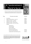
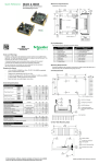
Tips Operation 1. Tip installation: Simply screw the dedicated tip onto the handset front. Make sure the tip matches the connector type you want to inspect. (In order to keep the optics inside the handset clean, make sure that the tip to be installed is clean.) 2. Insert the tip into the connector adapter housing until the adapter stops the movement. Adjust the focus by rotating the wheel on the handset as shown in Fig. 5. The standard package includes a tip for LEMO F2 contacts LC/PC female connectors and a tip set for FC/PC & SC/PC female connectors. Options include ― Tips for other types of female connectors; and tips for male connectors ― Slim tips (0° or 90°) for applications with tight access. FIBRE-OPTIC CONNECTOR INSPECTION & CLEANING User’s Manual Safety Information Figure 5 3. A clear image of the connector end face can be obtained. • Never power on if any defect is observed. • To reduce the risk of injury and instrument damage, use only the specified battery packs. • Always follow the polarity sign of the battery pack when inserting it into the monitor module or the external charging housing. • Do not disassemble the handset. Any unauthorized attempt will void the warranty. • To reduce the risk of electric shook, unplug the AC adapter and the charger from the outlet before attempting any maintenance or cleaning. Battery Charging When the battery indicator LED shows ‘low’ (orange color), the battery should be recharged. (A battery pack can still support operation for >15 min from the point when the ‘Battery low’ indicator becomes on.) Steps for recharge: 1. Plug the pigtail connector of the Charger to the monitor module, and turn the switch to ‘CHARGE’. (See Fig. 6) 2. While charging, the ‘LED on the charger’ is red; once the battery is full, the ‘LED on the charger’ will turn to green. It takes 3.5 hours to charge from battery ‘empty’ to ‘full’. Switch to ‘CHARGE’ Charger plug Figure 6 Charger Note: During charging, the monitor does not operate. If you prefer an external charging, you can buy an external charging housing and additional battery packs from AEFOS. LEMO (UK) Ltd 15/16 Hazelwood Trading Estate Worthing West Sussex BN14 8NP www.lemo.co.uk [email protected] Tel: 01903 234 543 Fax: 01903 206 231 Setup Specifications UKT.0000659 (LCD version) CI-1000-A (LCD version Magnification 200x Field of Vision ~ 400 μm x 300 μm Focus Manual adjustment, 2mm max travel LCD Monitor ¼ inch colour CCD LCD Monitor 3.5”; TFT-LCD; High brightness & Contrast; High resolution; 600(H) x 240(V), RGB Delta Composite Sync.; View angle 110(H), 50(V) Handset Dimensions ∅32mm; 8” (including tip length) Power Supply Rechargeable battery packs (last min 4 hours) or AC adaptor Other Package Options USB version, or Handset version (for external monitor) Accessory Options - Tips for custom female connectors (Tips for female SC/PC, LC/PC connectors are included in standard package) - Tips for male connectors 1. Plug the handset cable connector into the socket on the back of the monitor module (refer to Fig. 1). If you use AC power: Plug the cable connector of the AC Adapter (i.e. the Charger) into the socket as shown in Fig. 1. Once this AC adapter is plugged in, the battery is disconnected from the system. Handset LCD monitor set Tip set for female FC/PC (1 tip body, 1 FC guide, 1 SC guide) Tip for female LC USB video capture device & software UKT.0000665 interface cable (w/ an F-M RCA converter attached to its RCA port Rechargeable battery pack Switching charger/ Power adapter Carrying case UKT.0000 665 (Handset version) 9 9 9 9 9 9 9 9 9 9 9 9 4-DIN connector to handset USB connector to your computer USB port Warning: Do NOT use this USB Video Capture Device in any other unspecified systems because this dedicated USB module includes a 5V to 12V DC/DC converter to draw electric current from your computer to support the inspector handset. The 12V voltage in its 4-DIN connector may damage devices in your unspecified systems. Switch AC adaptor / Charger Handset plug Figure 1 2. Follow the AEFOS Video Capture Software User’s Guide to Install and run the ‘USB Video Driver’ and ‘AEFOS Video Image Capture 1.0’ in your computer. ‘Work / Battery low’ indicator UKT.0000665 (Handset version) 3. There is a power switch on the side of the module base. As the sign indicated, there are three positions respectively for ‘WORK’, ‘OFF’, or ‘CHARGE’ (see Fig.2). Turn the switch to ‘WORK’. With a normal power supply (either from battery or from AC adapter), the LED should light green. Then, adjust the thumbwheels on the LCD panel to optimize the screen brightness & contrast. To allow the battery pack working longer, always remember to turn off this power switch during any long idle intervals or after daily operation. WORK 9 USB Video Capture Device CI-1000-USB1.1 Figure 3 Video signal output UKT.0000 671 (USB version) 9 1. Connect the CI-1000-USB1.1 Video Capture Device to the inspector handset as well as your computer USB port, as shown in Fig. 3. 2. If you use battery power: A 9.6V battery pack is inside the base of the monitor module. When the battery is charged, the ‘Work / Battery low’ Indicator LED shows green. But if the battery becomes low, the LED color turns to orange. (See section ‘Battery Charging’ for battery charging details.) Standard Packages UKT.0000 659 (LCD version) 9 9 9 UKT.0000671 (USB version) OFF 1. Connect the CI-1000 interface cable to the handset as well as the AC adapter, as shown in Fig. 4. CI-1000 interface cable 4-DIN connector to handset RCA connector RCA F-M converter Plug into monitor DC-IN connector to AC adapter CHARGE Figure 2 Note: The Video Signal Output port is for external monitor use. Once this port is plugged, the 3.5” internal LCD will be disconnected. Figure 4 2. Plug the RCA male connector into your monitor video input.