1
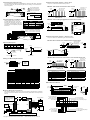
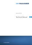
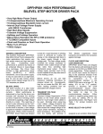
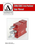
Quick Reference
Mechanical Specifications
IM483 & IM805
Dimensions in Inches (mm)
Miniature high performance
microstepping drivers
2.75
(69.9)
0.15
(3.8)
HMAX
2.45
(62.2)
1 2 3 4 5 6 7 8
3.00
(76.2)
P1, Pin 1
2.42
(61.4)
P2, Pin 1
0.29
(7.4)
0.03
(0.8)
1.00
(25.4)
4X Ø 0.190 (4.1)
HMAX
IM483: 1.20 (30.5)
IM805: 1.32 (33.5)
Pin Configuration
See Opposite Side for alternative connector options.
Connector P1 (Signals)
Function
Pin #
Notes and Warnings
Installation, configuration and maintenance must be carried out by qualified technicians only. You must have detailed information to be able to carry out this work. This
information can be found in the user manual.
• Unexpected dangers may be encountered when working with this product!
• Incorrect use may destroy this product and connected components!
The user manual are not included, but may be obtained from the Internet at:
http://www.imshome.com/downloads/manuals.html.
+12 to +48 VDC, 2A (IM483) or +24 to +75 VDC, 3.5A (IM805) unregulated
linear or switching power supply.
•
Stepping motor appropriately sized for your drive.
•
22 AWG wire for logic and I/O, 18 AWG wire (IM483) or 16 AWG wire (IM805)
for power supply. Shielded twisted pairs recommended.
•
Basic hand tools: wire cutter/stripper, screw driver.
2
Current Reduction Adjust
Current Adjustment
3
Direction Input
3
Power Supply Return (Ground)
4
Optocoupler Supply
4
Motor Power (+V)
5
Enable/Disable Input
5
Motor Phase B
6
Reset Input
6
Motor Phase B
7
Fault Output
7
Motor Phase A
8
Fullstep Output
8
Motor Phase A
IM483
IM805
IM483
Phase Output Current
IM805
IM483
IM805
IM483
IM805
Condition
Min
Typ
Max
Unit
—
—
RMS
Peak
RMS
Peak
I/O Floating
I/O Floating
IOUT= 3A RMS
IOUT= 3A RMS
+12
+24
—
0.4
1
—
—
—
—
—
—
—
—
—
—
—
70
13
12
9
+48
+75
3.0
4
5.0
7.0
—
—
—
—
VDC
VDC
A
A
A
A
mA
mA
W
W
Condition
Min
Typ
Max
Unit
—
—
5
—
—
7.0
1.5
—
—
—
15
1.7
—
25
140
mA
VDC
VDC
mA
VDC
I/O Specifications
Input Forward Current
Input Forward Voltage
Input Reverse Breakdown Voltage
Output Current
Collector-Emitter Voltage
Isolated Inputs
Fault, Fullstep Outputs
Fault Output
Fault (ICS=25 mA)
—
—
0.2
VDC
Fullstep Output
Fullstep (ICS=25 mA)
—
—
—
6.5
100
—
VDC
Ω
Thermal Specifications
Min
Typ
Max
Unit
Storage Temperature
Ambient Temperature
Plate Temperature (Add't Cooling may be required)
-40
0
—
—
—
—
+125
+50
+70
°C
°C
°C
Motion Specifications
Min
Typ
Max
Unit
—
—
—
—
10
14
MHz
—
Collector-Emitter Saturation Voltage
6.00
(152.4)
0.85
(21.6)
5.50
(139.7)
3.51
(89.5)
Electrical Specifications
Drain-Source Voltage
Drain-Source On Resistance
1
Step Clock Input
H-4X Heat Sink Kit
General Specifications
Active Power Dissipation
No Connect
2
The IMx is designed to be mounted to a heat sink or inside a panel. IMS offers both a
Heat Sink Kit (H-4X) and Side Mounting Clips (U3-CLP)
•
Quiescent Current
1
Mounting Requirements
Required for Setup
Input Voltage Range
Connector P2 (Motor and Power)
Pin 1
Function
3.15
(80.1)
6X32 Threaded 4 Places
A
A
(4) 6-32 x 1/2 Screws
B
B
(4) #6 Split Lock Washers
C
C
(4) #6 Flat Washers
D
(1) TN-48 Non-Isolating
Thermal Pad, Adhesive Side
to Drive
D
H-4X Heat Sink
Step Clock Rate
Number of Microstep Resolutions (See Resolution Table)
U3-CLP Side Mounting Clips
3.36
(85.34)
0.50
(12.7)
A
B
A
IM483 or IM805
B
#10 Mounting Hardware
(Not Supplied)
C
(2) U3-CLP Mounting Clips
D
Mounting Panel or Plate
C
D
All documentation, software, program examples and resources are available
online at: http://www.imshome.com/products/discrete_drivers.html.
IM483 and IM805 Quick Reference R021610
Controlling the Output Current
Alternate Connector Options - 8-Pins at P1
A Current Adjustment Resistor is REQUIRED to operate the IMx driver. Optionally,
the output current may be automatically reduced to a holding current level after a
motion completes.
B
EQ. A
RADJ= IPEAK X 500
3 2 1
P2
= 500 X
8X 0.045 (1.14)
SQ. Post Tin
Plated Bronze
0.200
(5.1)
0.720
(18.3)
0.914
(23.2)
0.811
(20.6)
I RUN X I HOLD
I RUN
I HOLD
-
Connector P1
Connecting Motor and Motor Power
This document shows connection of
a 4-lead stepping motor. For 6 and
8-lead motor connection see the product manual. Use the table on the right
to determine the acceptable per-phase
inductance.
8X 0.025 (0.64)
SQ. Post Tin
Plated Bronze
0.200
(5.1)
0.820
(20.8)
EQ. B
R RED
IMx-8P2 - 8-Pin Posts at Connectors at P1 and P2
Current Adjust Resistor
(1/8W 1%Ω) See EQ. A.
Reduction Adjust Resistor
(1/8W 1%Ω) See EQ. B.
A
B
A
The pin-out is identical to standard IMx products.
Connector P2
IMx-PLG - 8-Pin Locking Pluggable Connectors at P1 and P2
Max Inductance Per Phase (mH)
IM483
IM805
2.5
—
5
5
8
8
+V
+12
+24
+40
+48
10
10
+75
—
15
Phase B
Phase B
Phase A
Phase A
0.200
(5.1)
P2:1
P2
Connector P1 and P2
+
Orientation
Power
Supply
8 7 6 5 4 3
P1:1
0.472
(12.0)
Linear Unregulated or Switch Mode
IM483: +12 to +48 VDC ± 10% Ripple
IM805: +24 to +75 VDC ± 10% Ripple
-
8X 0.040 (1.02)
SQ. Post Tin
Plated Bronze
Alternate Connector Options - 34-Pins at P1
The pin-out allows for additional signals. See table below.
Stepping Motor
IMx-34P1: 34-Pin Header at P1, Standard Screw Terminal at P2
Opto-Isolated Inputs
Current Limiting Resistor Values
+VDC
RLIMIT
10
681
5
–
12
15
24
1000
1300
2670
Controller
Output
0.500
(12.7)
+5 VDC
Opto Supply P1:4
Controller
Output
Isolated Input
RLIMIT *
1/4 W 1%
Connector P1
0.41
(10.4)
1
Isolated Input
17
18
Open Collector Interface
34X 0.025 (0.64)
0.100
SQ. Posts Tin
(2.54)
Plated Bronze
0.100
(2.54)
0.220
(5.6)
0.025
(0.6)
34
TTL Interface
IMx-34P1-8P2: 34-Pin Posts at Connectors at P1 and 8-Pin Posts at P2
Setting the Microstep Resolution
1
OFF/HIGH/1
2
ON/LOW/0
3
0.100
(2.54)
1 = MSEL0
2 = MSEL1
3 = MSEL2
4 = MSEL3
0.100
(2.54)
8X 0.025 (0.64)
SQ. Post Tin
Plated Bronze
0.520
0.800 (13.2)
(20.3)
4
8X 0.045 (1.14)
SQ. Post Tin
Plated Bronze
0.200
(5.1)
0.914
(23.2)
0.811
(20.6)
MSEL Switch
Resolution
Microsteps/Step
2
4
8
16
32
MSEL 0 MSEL 1
SW1:1
SW1:2
Binary Resolutions
400
0
0
800
1
0
1600
0
1
3200
1
1
6400
0
0
Steps/Rev
MSEL 2
SW1:3
MSEL 3
SW1:4
0
0
0
0
1
0
0
0
0
0
Connector P1
Pin #
64
12800
1
0
1
0
128
25600
0
1
1
0
256
51200
1
1
1
0
5
1000
0
0
0
1
2000
1
0
0
1
25
5000
0
1
0
1
50
10000
1
1
0
1
125
25000
0
0
1
1
250
50000
1
0
1
1
Function
Pin #
16, 26
Function
3
Resolution Select 3
On-Full-Step Output
4
Step Clock Input
21
Step Clock Output (Non-Isolated)*
6
Direction Input
22
Direction Output (Non-Isolated)*
8
Optocoupler Supply
23
Resolution Select 0
10
Enable/Disable Input
24
Resolution Select 1
12
Reset Input
25
Resolution Select 2
14
Fault Output
27
Logic Ground (Non-Isolated)
*Step/Direction outputs follow the inputs at a 1:1 Ratio.
Decimal Resolutions
10
Connector P2
BB-34 Breakout Board
2.441
(62.00)
0.107
(2.72)
2.635
(66.92)
2X Ø 0.155
(3.94)
Minimum Required Connections
The following illustration shows the minimum connection requirements for operating
the IMx. For use and interface of the other I/O Points please refer to the full product
manual.
* All Opto-Isolated inputs
should be referenced to
the Opto Supply Ground
for Isolation, Not Drive
Power Ground.
+5 VDC
Supply*
+
-
Step Clock**
Stepping Motor
17
1
18
Pin 10: Enable Input
Pin 8: Opto Supply
Pin 3: MSEL3
8
7
6
5
P2
4
3
2
1
Phase A
Phase A
Phase B
Phase B
+V
GND
RADJ
1
18
+
-
Pin 12: Reset Input
Pin 14: Fault Output
Pin 16: On-Full-Step Output
17
34
Power
Supply
Direction Switch**
** If an Opto Supply voltage greater than +5 VDC is used, a current
limiting resistor is REQUIRED in series with the Input!
Copyright © Schneider Electric Motion USA
0.780
(19.81)
34
Pin 6: Direction Input
1
2
3
4
P1
5
6
7
8
1.050
(26.67)
www.schneider-electric-motion.us
Pin 21: Step Out
Pin 22: Direction Out
Pin 23: MSEL0
Pin 24: MSEL2
Pin 27: Ground
Pin 26: On-Full-Step Output
Pin 25: MSEL1