1
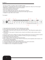
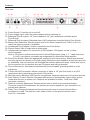
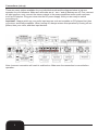
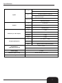
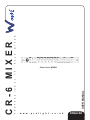
R
E
P
R
O
F
E
S
S
I
USER MANUAL
O
N
A
L
1
9
”
R
A
C
K
M
I
X
CR-6 MIXER
Order Code: MIXE01
w w w . p r o l i g h t . c o . u k
ENGLISH
WARNING
FOR YOUR OWN SAFETY, PLEASE READ THIS USER MANUAL CAREFULLY
BEFORE YOUR INITIAL START-UP!
CAUTION!
Keep this equipment away from rain,
moisture and liquids.
SAFETY INSTRUCTIONS
Every person involved with the installation, operation & maintenance of this
equipment should:
-
Be competent
-
Follow the instructions of this manual
CAUTION! TAKE CARE USING THIS EQUIPMENT!
HIGH VOLTAGE-RISK OF ELECTRIC SHOCK!!
Before your initial start-up, please make sure that there is no damage caused during
transportation. Should there be any, consult your dealer and do not use the
equipment.
To maintain the equipment in good working condition and to ensure safe operation, it is necessary
for the user to follow the safety instructions and warning notes written in this manual.
Please note that damages caused by user modifications to this equipment are not
subject to warranty.
2
IMPORTANT:
The manufacturer will not accept liability for any resulting damages caused
by the non-observance of this manual or any unauthorised modification to the
equipment.
• Never let the power-cable come into contact with other cables. Handle the power-cable
and all mains voltage connections with particular caution!
• Never remove warning or informative labels from the equipment.
• Do not open the equipment and do not modify the equipment.
• Do not switch the equipment on and off in short intervals, as this will reduce the
system’s life.
• Only use the equipment indoors.
• Do not expose to flammable sources, liquids or gases.
• Do not carry the unit with only one handle. Always carry using both handles.
• Always disconnect the power from the mains when equipment is not in use or before
cleaning! Only handle the power-cable by the plug. Never pull out the plug by pulling the
power-cable.
• Make sure that the available voltage is between 220v/240v.
• Make sure that the power-cable is never crimped or damaged. Check the equipment and
the power-cable periodically.
• If the equipment is dropped or damaged, disconnect the mains power supply immediately.
Have a qualified engineer inspect the equipment before operating again.
• If the equipment has been exposed to drastic temperature fluctuation (e.g. after
transportation), do not switch it on immediately. The arising condensation might damage
the equipment. Leave the equipment switched off until it has reached room temperature.
• If your product fails to function correctly, discontinue use immediately. Pack the unit
securely (preferably in the original packing material), and return it to your Prolight dealer
for service.
• Only use fuses of same type and rating.
• Repairs, servicing and power connection must only be carried out by a qualified
technician. THIS UNIT CONTAINS NO USER SERVICEABLE PARTS.
• WARRANTY; One year from date of purchase.
OPERATING DETERMINATIONS
If this equipment is operated in any other way, than those described in this manual,
the product may suffer damage and the warranty becomes void.
Incorrect operation may lead to danger e.g.: short-circuit, burns, electric shocks,
lamp failure etc.
Do not endanger your own safety and the safety of others!
Incorrect installation or use can cause serious damage to people and property.
3
Features
• Six lines including one phono, three microphone inputs
• Microphone 1 is equipped with auto-override, sensitivity adjustment, delay time, EQ, and gain.
• Balanced microphone inputs on front and rear panels
• (Front panel) Channel on/off switches
• Dual zone assignment for all inputs
• Two zone outputs with gain, pan, EQ, and stereo/mono selection
• Zones have unbalanced and balanced outputs with master gain reduction
• Headphone output with volume control
Front panel:
1. Input gain knobs (6 channels): Control individual source levels.
2. On/off switches: Allow input sources to be individually selected.
3. Zone assign: Determines which zone the audio is directed to. The A+B position sends audio to
both Zones.
4. Microphone 1 Gain control: Controls the mic volume for the Neutrik combo connector on the
front panel.
5. Microphone EQ controls: Adjusts the Treble, Mid and, Bass frequencies of the microphone inputs.
6. Neutrik Combo Connector: Allows connection of either a 1/4” jack or an XLR plug.
7. Zone Knob:Controls the output level.
8. Mono/ Stereo: Selects the mode for the sound output.
9. Pan: Controls the mix of stereo audio. Moved to the left only the left speakers will be heard, or to
the right for the right speakers.
10. Level Indicator: Shows the level of sound output.
11. Zone EQ: Adjusts the Treble, Mid and Bass frequencies of the zoned audio.
12. Headphone Gain Control: Adjusts the headphone volume.
13. Headphone Jack: for headphones connection.
4
Features
Rear view:
14. Power Switch: Turns the unit on and off.
15. Power supply input: Insert the power adapter before switching on.
16. Balanced Zone B outputs: 1/4” stereo balanced 1/4” jack connectors controlled by the
Zone B knob.
17. Balanced Zone A outputs: Balanced stereo XLR connectors controlled by the Zone A knob.
18. Master Gain Reduction: Sets the output level of the Zone A outputs from 0.245V to 2.5V to
match the optimum inputs of amplifiers.
19. Unbalanced Zone Outputs: Output controlled by the Zone knobs.
20. Record Output: Mix of output sent to either zone.
21. Unbalanced Line Inputs: For connection of DVD players, CD players, tuners, or other
mixing consoles.
Note: a. Plug mono audio sources into both Left and Right inputs using a “ Y “ cable connector.
b. Line 3 can receive a turntable input depending on phono/line switch position.
22. Phono/Line Switch: Select the appropriate position for your input device. With phono selected
the input signal is fed directly to the high-quality RIAA phono pre-amplifiers so use this input only
for turntables. Line level sources will overload the sensitive phono pre-amps. Switch this over to
the Line position for line devices such as CD players and mixing consoles.
23. Ground connection: Use these connections with your turntables’ grounding cable to avoid
signal hum.
24. Combo Jack/XLR connector: Allows connection of either a 1/4” jack (line level) or an XLR
(microphone level) depending upon switch (25) position.
25. Mic/Line switch: Balanced XLR input for microphones, balanced Jack input for line level sources
26. Auto-Talkover Control: Sets the front panel Microphone to automatically reduce other source
levels when the mic is spoken into. Positions are available for either, -12dB, and -40dB
(complete reduction).
27. Talkover sensitivity adjustment: Determines the point in which auto-override activates.
The more sensitive the adjustment, the quieter you need to speak into your microphone to
activate auto-talkover.
28. Delay Time: Changes the speed and the music inputs return to normal volume after a
microphone is used. The time the music takes to return to the pre-set volume varies
from 0.5~ 4 seconds.
5
Connections (set up)
There are many options available for your individual needs and the diagram below is just one
example for your reference. Make sure all knobs are at “ zero “ and all devices are off. First, connect
all input sources; next, connect the stereo outputs to the power amplifiers and/or audio receivers
such as CD players. Plug your mixer into the AC power supply. Now you are ready to switch
everything on.
Important: Always switch on your audio input sources such as turntables or CD players first, then
your mixer, and finally amplifiers. When turning off, always reverse this operation by turning off amplifiers, then your mixer, and then input devices.
Note: Incorrect connection will result in malfunction. Make sure the connection is correct before
operation.
6
Specifications
10k input impedance
Line
140mV rms sensitivity ( for 1.4V balanced output )
10K input impedance un-balanced
Inputs
Mic 1
1.5mV rms sensitivity ( for 1.4V balanced output);
60mV rms max input
10K input impedance
Mic2/ Mic3
Outputs
1.5mV rms sensitivity ( for 1.4V balanced output);
80mV rms max input
Line
9V rms max
Headphone
0.5 Watt into 47 ohm
Distortion
Less than 0.01%
Line
> 87dB
Mic1
> 72dB
Mic2/Mic3
> 72dB
Phono
> 70dB
Line
20 ~ 22KHz +/- 0.5dB
Mics
20 ~ 20KHz +/-1.5dB
Phono
+/- 1dB except for controlled attenuation of -3dB
@20Hz to reduce rumble and feedback
S/N ratio (vs. max output )
Frequency Response
Equalizations
( Mic1/Zone A/ Zone B)
Bass +/- 20 dB
Middle +/- 15 dB; Treble +/- 14 dB
Power supply
+/-15VDC
Dimension (W × D × H)
483 (W) x 200 (D) x 44( H) mm
Net weight
2.2 KGS
7