1
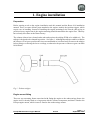
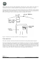
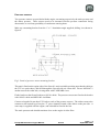
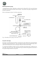
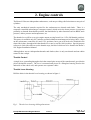
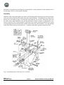
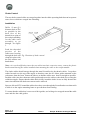
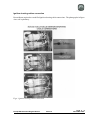
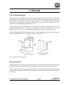
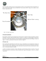
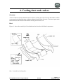
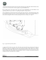
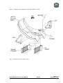
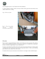
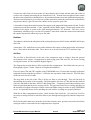
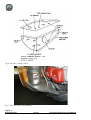
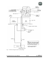
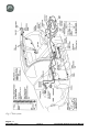
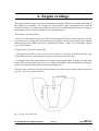
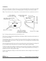
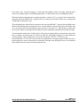
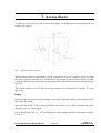
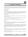
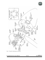
Europa XS
Rotax 914 Installation Manual
Europa XS Rotax 914 Engine Manual
Issue 7
October 2004
Index of Chapters
Chapter
Description
1
Engine installation
2
Engine controls
3
Oil tank
4
Cooling duct and coolers
5
Fuel system
6
Engine cowlings
7
Access doors
8
Propeller and spinner
9
Commissioning the engine
Annex A
Final inspection checklist
September 2002
Issue 5
Europa XS Rotax 914 Engine Manual
1. Engine installation
Preparation
Before starting work on the engine installation read this manual and the Rotax 914 installation
manual. There are some delicate parts attached to the engine, notably the ignition triggers, which
require care in handling. Instead of installing the engine mounting to the aircraft, then trying to
position a heavy engine onto it, the engine mounting should be attached to the engine first. This may
have already been done at the Rotax factory.
The exhaust silencer has a slotted outlet stub and requires the tailpipe EX08 to be added to it. The
tailpipe is designed to be clamped in position. See figure 1. Although the tailpipe could be welded to
the silencer, for tri-gear operators this is not recommended as it is often better to remove the tailpipe
before fitting or removing the lower cowlings, as otherwise the presence of the nose gear can make
life difficult.
Fig 1. Exhaust tailpipe.
Engine mount fitting
There are two mounting frames associated with fitting the engine to the undercarriage frame: the
engine itself is already fitted to a ring mount which is a Rotax component, and that is fitted to the
Europa engine mount, which in turn is fitted to the undercarriage mount.
Europa XS Rotax 914 Engine Manual
Issue 6
Page 1 - 1
September 2003
Fit the engine mounting frame to the Rotax ring mount using M10 x 110 bolts and M10 Binx nuts.
The upper bolts and the lower port bolt should be fitted with the bolt heads aft, and the lower
starboard bolt with the head forward. The excess length of the bolts will need to be cut off, leaving a
minimum of two threads emerging from the end of the nut. It will be necessary to chamfer the lower
starboard bolt’s head as shown in figure 2.
Engine installation
Mount the engine to the landing gear frame using the rubber mountings. See figure 2
To check the orientation of the engine, set the fuselage level using the port door sill as the reference as
usual. Check that the propeller flange is truly vertical.
The engine mounting frame has been designed with the engine offset to starboard by 1.5° To check
that this offset is correct clamp a straight edge to the propeller flange horizontally and mark a point
51 cm (20") each side of the engine centre line. Measure the distance from these points, parallel to the
aircraft centre line, to the firewall. The difference between the two readings should be 26 mm
(1-1/16"). If any correction is found necessary, shim between the landing gear frame and the
appropriate cup washer using AN960-516L washers. In order to ensure that the split pin is correctly
positioned relative to the castellated nut it will be necessary to use a total of at least 4 washers on each
bolt. Any washers that are not needed to act as positioning shims should be placed immediately
under the nut. Make a note of where and how many shim washers are used for later reference.
Note: The 4 AN5-41 mounting bolts must be tightened fully to compress the rubber anti-vibration
mounts (MT04) onto the steel spacers (MT03).
Caution: It should be noted that before the two ignition leads which come from the ignition box are
earthed, the ignition is ”live”. Even though the engine speed must be at least 1200 rpm for the
ignition to fire, it would be a sensible precaution to fit the magneto switches before further work is
carried out on the engine, or at least temporary earth leads connecting the ignition wires to the
engine casing.
Wastegate control
The turbocharger wastegate is controlled by the TCU and operated by the servo motor unit. These
two items have to be positioned away from sources of high temperatures. Consequently they are to
be fitted in the cabin on the top of the tunnel right at the front behind the firewall.
Servo motor
The servo motor is mounted horizontally on the right of the tunnel, with the operating cable facing
forwards. The positions shown in figure 3 are suggested but, depending on the equipment in the
instrument panel, you may have to site them elsewhere.
Be careful to take into account the length of the already made up cables which connect the various
engine related components together before making your final decision on their positions.
Page 1 - 2
June 2004
Issue 7
Europa XS Rotax 914 Engine Manual
Fig 2. 914 engine installation exploded view.
Europa XS Rotax 914 Engine Manual
Issue 7
Page 1 - 3
March 2006
When cutting the necessary holes through the firewall for the various cables, keep them to a
minimum size and use a suitable method of sealing around the cables after they are in place.
Having positioned the servo motor, mark out the mounting holes. Fit two MS21047-4 anchor nuts on
top of the tunnel, using TAPK33BS rivets. The unit is mounted with two spacers on each AN4-17A
bolt, one W14 spacer, and one shorter spacer made by cutting a W14 in half.
Figure 3. Position of servo motor and TCU. View looking forward.
Turbo control unit
This unit is mounted vertically on firewall on the cabin side, in the position shown in figure 2.
The four mounting bolts pass through the firewall with the nuts in front of it. Since the thread length
of the bolts is rather short it will be necessary to make the appropriate part of the firewall thinner.
Using a 20 mm (3/4") hole saw, carefully drill through the forward skin and foam only. Bond
NAS1169C10 Tinnerman washers into the recess with flox, ensuring that the recessed face of the
washers is kept clear of the flox. Mount the unit with spring washers and M4 nuts.
Page 1 - 4
September 2003
Issue 6
Europa XS Rotax 914 Engine Manual
Pressure sensors
Two pressure sensors are provided with the engine, measuring respectively the static pressure and
the airbox pressure. These sensors need to be mounted with the pressure connection facing
downwards, to avoid any possibility of condensate entering them.
Make up a mounting bracket from the 1" x 1" aluminium angle supplied, drilling it as shown in
figure 4.
Fig 3. Detail of pressure sensor mounting bracket.
This unit is fitted on the engine side of the firewall - mark a suitable position (note that the cables to
the TCU are quite short), and drill through the firewall with a 4.8 mm drill. Fit two MS21047-3
anchor nuts on the cabin side, riveting them with TAPK36BS rivets.
Fit the bracket to the firewall with two AN3-4A bolts. The pressure sensors are fitted to the bracket
with AN4-5A bolts and MS21042-4 stiffnuts.
Connect a length of 4 mm bore PVC tube to each of the pressure sensors. The airbox sensor tube
connects to the unused leg of a nylon “T” piece situated forward of the airbox on the port side. A
water trap is supplied with the engine, and it should be fitted in the line.
The static pressure tube should terminate close to the engine air inlet filter.
Europa XS Rotax 914 Engine Manual
Issue 6
Page 1 - 5
September 2003
Manifold pressure gauge
A manifold pressure gauge, calibrated to read between 10 in. Hg and 50 in. Hg, is provided, along
with all the necessary parts to plumb it into the engine. The position of the gauge is suggested to be
beside the tachometer.
Refer to the diagram in figure 4 for all the connections.
Fig 4. Manifold pressure gauge connections.
Propeller drive lugs
The engine is normally delivered with the six propeller drive lugs suitable for the ground adjustable
Warp Drive propeller supplied loose. These are a light interference fit in the propeller flange, with a
relief on the forward part to assist in starting the insertion of them into the flange.
To complete the installation it will be necessary to pull them into position using a suitable bolt, nut,
and washer, with a spacer tube. Ensure that the drive lugs are fitted with no gap between the back of
the propeller flange and the drive lug collar.
Page 1 - 6
February 2005
Issue 7
Europa XS Rotax 914 Engine Manual
2. Engine controls
The Rotax 912 has two independent carburettors, each one providing a fuel/air mixture to one pair of
cylinders.
The only mechanical controls required for the carburettors are throttle and choke. There is a
computer controlled turbocharger wastegate control, which varies the boost pressure in response
primarily to demand from throttle position, but limited also by other functions such as RPM, static
pressure, airbox pressure and temperature, etc.
The throttle lever will be set to give engine output varying from 0% to 115% (full throttle position).
This power is available only for 5 minutes, normal continuous maximum power being 100%. Stops
on the carburettors control the 0% and 115% positions, but a gate will need to be included in the
slotted facia plate, through which the throttle lever runs, to set the 100% position. Special purpose
software is used with which to set the throttle stops, details of which are to be found in the Rotax’s
914 Engine Installation Manual
Although there are two independent throttles and chokes, there is only one throttle and one choke
control in the cockpit.
Throttle Control
A single lever, protruding through a slot in the central spine on top of the central tunnel, provides the
pilot with throttle control. The lever is mounted and pivots in a fibreglass housing fixed to the
underside of the wheel well, and operates two separate cables.
Throttle Lever Housing
Drill the holes in the throttle lever housing, as shown in figure 1.
Fig 1. Throttle lever housing drilling dimensions.
Europa XS Rotax 914 Engine Manual
Issue 9
Page 2 - 1
April 2006
Drill also a 4.8 mm hole in each flange for mounting bolts. Open up the hole on the starboard side of
the housing to allow a socket spanner through.
Assembly
Install the cable outers through the two holes in the housing and clamp them in position using the
nyloc nut with an AN960-416L washer each side of the fibreglass. Assemble the two cables to the
throttle lever according to figure 3 ensuring the end fittings are free to pivot. Thread the cables into
the cable outers, then install the lever into the housing as shown in figure 2, adjusting the lever
friction as desired. The friction should be sufficient to prevent the carburettor throttle lever spring
from opening the throttle automatically, and this can be done after final assembly. Cover the opening
in the side of the housing to keep dirt out - a suitably sized rubber grommet would be ideal.
Fig 2. Exploded diagram of throttle lever assembly.
Page 2 - 2
November 2004
Issue 8
Europa XS Rotax 914 Engine Manual
Installation
The throttle lever housing should be positioned such that its front face is 380 mm (15") aft of the
firewall. For the monowheel aircraft this will ensure clearance with the main wheel top when it is
retracted. Mark out and cut a slot for the throttle lever in the spine in the centre tunnel then,
checking that full throttle travel is achievable, drill through the flanges for mounting bolts.
For ease of installation attach an MS21047-3 anchor nut to the underside of the housing’s flange at
each end using TLPK 424 BS rivets then, using AN525-10R10 bolts, secure the housing in place.
The front mounting will use an AN970-3 washer, see figure 2, and an AN970-3 washer can be used
temporarily to hold the rear of the mounting until it is substituted by the throttle closed stop.
Fit the throttle knob parts TH07 using an AN525-10R10 bolt and MS21042-3 nut to the top of the
throttle lever to complete the installation.
Slot the throttle cables through the gap between the firewall and the upper mounting members of the
landing gear frame, securing them to the frame with tie wraps to prevent chafing. Remove and
discard the straight cable-outer receptacle provided on each carburettor and in its place insert the
throttle cable’s threaded end. Use one check nut each side of the bracket to clamp the cable-outer in
place. The cables may seem excessively long, but this is to allow large bend radii in the engine bay to
ensure minimum friction.
Each throttle cable should emerge through the metal firewall on the opposite side to the carburettor
that it will control. Loop the cable up and aft towards the centre of the firewall, then down into the
bracket of the appropriate carburettor. Loosely secure the two cables where they cross.
Insert the cable inner into the nipple on the carburettor throttle lever, which is sprung to its full open
position. Setting the throttle lever in the cockpit back about 2-3 cm (1") from its full forward position,
screw both nipples tight on the cables. Check for full throttle movement, making any adjustments as
required, then seal the open hole in the throttle lever housing to prevent anything thrown up from the
wheel from entering.
Throttle closed stop
The addition of a throttle-closed stop is important to avoid the possibility of excess tension on the
throttle cable causing loss of throttle control. Following the method below, prepare a plate, made
from 3 mm (1/8”) aluminium, 50 mm (2”) wide. With the throttle closed, and the slow running
adjustment correctly set at the carburettors, measure the distance from the rear of the throttle lever,
where it protrudes above the top of the tunnel, to the centre of the rear 4.8 mm (3/16”) mounting hole.
The plate length will be 6 mm (1/4”) more than this measurement. Drill the plate 6 mm (1/4”) from
one end, bond with Redux to the tunnel, and bolt with an AN525-10R10 bolt.
Note: You should set the throttle closed stop such that a fully warmed engine idles at 1200 1400 rpm. Although the engine idles more smoothly at 1600 rpm or more, when landing the aircraft
you will benefit from minimal residual thrust.
Europa XS Rotax 914 Engine Manual
Issue 9
Page 2 - 3
April 2006
Choke Control
The two choke control cables are swaged together into the choke operating knob but run in separate
outer sleeves which are swaged into a housing.
Installation
Drill a 13 mm (1 2“)
diameter hole as low
as possible in the
b ac k fa ce o f t he
throttle lever spine of
the cockpit moulding
for the cable outer
as s e mb l y t o go
through. See figure
3.
Push the threaded
p o rt i o n o f t he
cable-outer housing
through the hole and Fig 3.Position of choke control.
clamp it in place with
the lock washer and
knurled nut.
Note : As it can be difficult to insert the two cables into their respective outers, remove the plastic
knob instead leaving the cables installed when mounting the outer to the cockpit module.
The choke cables should emerge through the metal firewall as do the throttle cables. Loop these
cables forward over the top of the engine so that they enter the 90° elbow guides mounted on the
carburettor from the front. Rotate the elbows so that the cables enter them as straight as possible.
Push the cables into the carburettor cable guides and secure the cables to the choke levers using the
solderless nipples. Ensure that the choke knob is fully in and the choke levers are fully down at the
same time and that full choke movement can be achieved.
Squeeze silicone RTV around the cables where they come through the firewall and secure them with
a cable tie to the engine mounting frame to prevent them from chafing.
To ensure that the cables don’t come out of their guides, use locking wire wrapped around the cable
outer and also the cable guides.
Page 2 - 4
April 2006
Issue 9
Europa XS Rotax 914 Engine Manual
Ignition shorting cables connection
Recent Rotax engines have modified ignition shorting cable connections. The photographs in figure
4 are self-explanatory.
Fig 4. Ignition shoring cables connection.
Europa XS Rotax 914 Engine Manual
Issue 10
Page 2 - 5
November 2007
INTENTIONALLY BLANK
Page 2 - 6
November 2007
Issue 10
Europa XS Rotax 914 Engine Manual
3. Oil tank
Oil Tank Mounting Bracket
The oil tank is to be mounted to the front of the starboard footwell using a steel bracket. To make the
mounting bracket first mark out and cut out the steel sheet LB01 according to the drawing at the end
of this chapter. Next, bend the central wide portion into a curve to match the outside of the oil tank.
This can be accomplished by running the metal backwards and forwards across the corner of a
wooden bench whilst applying a bending force on it.
Finally, bend the lugs each side of the curved portion so that the two narrow flanges can sit flat
against the footwell front face. See figure 1. Bending can be done by clamping the steel between
lengths of wood in a vice. Try to avoid a sharp bend radius, a 10mm (3/8") radius is ideal.
Make a 90° angle bracket from the narrow strip shown on the template and rivet it to the top right port
side using TLPD424BS rivets -it should fit on top of the footwell.
Fig 1. Oil tank mounting bracket.
Bracket installation
Arranging the bracket with the upper lug fitting under the oil tank lid, fasten the bracket to the tank
using the two number 6X size jubilee clips. Keep the clamps away from the radius of the bracket.
With the engine and lower cowling in place position the oil tank and bracket onto the front face of the
starboard side footwell. Position the tank so that there is reasonable clearance from both the engine
and cowling.
Europa XS Rotax 914 Engine Manual
Issue 4
Page 3 - 1
September 2001
Drill through the bracket into the forward and top surfaces of the starboard footwell and bolt it in
place using AN525-10R10 bolts and MS21042-3 nuts with AN970-3 large area washers on the
inside to spread the load .
To oil p um p
Ve nt line
Re turn from sum p
To oil c oole r
Fig 2. Oil tank connections.
Oil tank installation
Reinstall the oil tank to its mounting bracket and orientate it so that the oil tank return fitting, which is
identified as the pipe which enters the tank at a tangent, is pointing to aft and slightly to starboard.
Screw the two 90° elbow fittings to the tank fittings, arranging the tank return fittings as shown in
figure 2. Connect up the hoses to the tank as shown in figure 2.
Oil tank vent
The vent from the oil tank allows an oil mist to escape to atmosphere. It is not unusual to run the vent
line to the bottom of the cowling, however if you do this, don’t position the end of the tube such that it
will be in the airstream whilst flying. This could cause low pressure at the end of the tube to suck
more oil from the tank than it should.
Another consideration is that the oil mist will tend to coat the fuselage if left to vent freely. To avoid
this you can run the vent line into a collector bottle before it goes to atmosphere; however, no bottle
is provided.
Page 3 - 2
September 2001
Issue 4
Europa XS Rotax 914 Engine Manual
4. Cooling duct and coolers
Overview
A duct is fabricated from aluminium sheet to direct cooling air to the oil cooler and radiator, which
are arranged one behind the other, with the radiator in front of the oil cooler. The duct is open at the
bottom and uses the inside of the bottom cowling as the lower seal.
Duct
Figures 1 shows the assembly of the aluminium duct from the individual components.
Fig 1. Assembly of cooling duct.
Europa XS Rotax 914 Engine Manual
Issue 4
Page 4 - 1
September 2001
Check the fit of the duct in between the footwells, and if necessary adjust the width of the duct, then
rivet the CD1, CD2 and CD3 sections together using TAPD46BS rivets.
Rivet sealing strip to the bottom sides of the duct using TAPD46BS rivets with EUR011 load
spreading washers to prevent the rivets pulling through the sealing material.
The assembled duct is fitted to the footwell using three bolts each side. The height and angle of the
duct should be arranged to provide a clearance underneath the exhaust silencer of approximately 5
mm, and be arranged to fit the air intake opening in the lower cowling. See figure 2.
Fig 2. Approximate position of duct.
A single AN3-5A bolt screws the side of the duct onto the inside face of the footwell using an
MS21047-3 anchor nut, installed in reverse into the footwell using TAPK 36 BS rivets to make it
nearly flush; the brackets CD4 and CD5 are then bolted to the duct and to the front faces of the
footwell, again using AN3-5A bolts - these should have AN970-3 washers to spread the load into the
fibreglass structure, and MS21042-3 stiffnuts.
Page 4 - 2
June 2004
Issue 7
Europa XS Rotax 914 Engine Manual
Figure 3 illustrates the mounting of the duct and the coolers.
Fig 3. Installation of duct and coolers.
Europa XS Rotax 914 Engine Manual
Issue 4
Page 4 - 3
September 2001
The photographs, figures 4 and 5 illustrate the duct installation.
To ensure adequate cooling it will be necessary to blank off the gap between the bottom of the
radiator and the lower cowling
Fig 4. Side view of duct.
Fig 5. Front view of duct
s h o w in g
radi at or
(non-typical exhaust shown).
Oil cooler
The oil cooler is mounted behind the radiator and is bolted to the duct top plate CD1 with four
AN4-5A bolts and MS21042-4 stiffnuts. Two unions are supplied- one straight and one right angled.
Fit these so that the straight fitting is on the starboard side.
To improve oil cooling in hot climates the oil cooler can be lowered approximately 2” (50mm) so that
it fits against the lower cowling; use longer bolts with appropriate spacers. In this case the blanking
plate fitted below the radiator will not be needed.
For details of the oil system connections see the schematic view at figure 9 at the end of this chapter.
Page 4 - 4
September 2001
Issue 4
Europa XS Rotax 914 Engine Manual
Connect one side of the oil cooler to the 90° union fitted to the oil tank, and the other side of the oil
cooler to the oil pump inlet using the pre-formed hose C06. Trim the short straight section to attach
the hose to the pump inlet so that the hose is the maximum distance from the right hand exhaust pipe.
The hose runs aft and up to go over the rear cylinder water hose, under the starter motor and inside the
ring mount, thence it goes down to the radiator on the opposite (port) side.
Connect the oil sump drain at the bottom of the engine to the tangential fitting on the oil tank. For this
connection use the hose marked “Conti” supplied with the Rotax engine. Set the banjo union at the
bottom of the engine to point to the right and approximately 30° forwards. The hose curves
immediately aft and up to go over the rear cylinder’s water hose, under the starter motor and inside
the engine ring mount; it then loops up to the tank.
Radiator
The radiator is bolted to the side plates of the cooling duct by two AN4-5A bolts and MS21042-4 nuts
each side.
A short hose, C05, leads from one port of the radiator to the engine coolant pump outlet, and a longer
hose, C04, leads to the header tank. These hoses are to be secured with 25-35 mm hose clips.
Air filter
The air filter is fitted directly to the end of the compressor and, to isolate it from the general
environment of the engine, a compartment is made using parts CD6 and CD7, the lower cowling
closing the bottom, see the exploded diagram figure 6.
The diagram shows what holes will be required in the compartment. Not all the holes are pre-cut.
Photographs, figures 7 and 8, illustrate a completed installation.
First rivet parts CD6 and CD7 together using TAPD46BS rivets. Position the assembly against the
starboard footwell with the top surface 13 cm below the top surface of the footwell. This will allow
sufficient room for the oil tank.
The large hole in the side of the CD6 is for the air filter to pass through. This will also help in
determining the location of the assembly. Drill through the rear face of CD6 and into the footwell
with a 4.8 mm drill for the three AN525-10R8 fixing bolts . Temporarily attach the assembly to the
footwell and check that the lower cowling will fit. The gap between the lower cowling and edges of
the assembly is bridged with strips of fabric reinforced rubber sealing riveted to it using TAPD46BS
rivets. It is probably best to leave attaching the seal until the cowlings are properly attached.
With the air filter compartment in place, check that the filter itself fits. On early kits it will be
necessary to enlarge the hole to allow the filter to pass through and engage fully onto the compressor
inlet.
Holes for the oil breather hose (from the neck of the oil tank), static pressure sensor tube and for the
wastegate cable to enter and exit the compartment are required.
Europa XS Rotax 914 Engine Manual
Issue 4
Page 4 - 5
September 2001
Fig 6. Air filter chamber detail.
Fig 7. Top view of air filter chamber.
Page 4 - 6
September 2001
Issue 4
Europa XS Rotax 914 Engine Manual
Fig 8. Lower view of air filter chamber.
Indication of where these holes should be are shown in the diagram, however actual positions are
best determined on the actual aircraft. Remember to use grommets in the holes to avoid chafing.
After final fitting of the air filter compartment secure the static pressure sensor tube so that its end is
about 4 - 5 cm within it. The oil breather hose should be routed so it can continuously drain.
Arranging it so that it vents close to the air filter will cause most of the oil mist to be ingested into the
engine and so reduce the amount which would otherwise run down the fuselage. Ensure that it
doesn’t exhaust such that oil can get onto the brake disc.
The wastegate cable needs to loop through the compartment to avoid sharp bends which would
inhibit its operation.
Europa XS Rotax 914 Engine Manual
Issue 4
Page 4 - 7
September 2001
Fig 9. Schematic view of oil cooling system.
Page 4 - 8
September 2001
Issue 4
Europa XS Rotax 914 Engine Manual
5. Fuel system
The installation of the fuel system described in the fuselage manual takes the fuel line as far as the
fuel selector valve. After the fuel has passed through the fuel valve the line connects to twin in-line
filters which are transparent and so aid visual detection of contamination. From the filters the lines
run to the twin electric pump inlets. The electric pumps are pilot activated, and are duplicated as the
Rotax 914 engine is not fitted with a mechanical pump. From the electric pumps the fuel lines join
again . This line is connected to the inlet of the fuel pressure regulator on the top rear of the engine. A
further line from the regulator takes a small flow of fuel back to the starboard side of the fuel tank.
The engine connection to this line incorporates an already fitted restrictor, to allow a flow of fuel to
prevent fuel vapourisation in hot conditions.
Installation
Electric fuel pumps
The electric pumps (supplied with the engine) are to be mounted in the port underfloor chamber
situated in the baggage bay floor.
Refer to the schematic diagram on page 3 and drawing on page 4 for details of the various fuel system
fittings.
Whilst the pump is not installed, either solder extension wires to the existing ones or attach
connectors for later use.
Inline filters
The in-line filters are to be connected between the selector valve and the fuel pumps.
Before mounting the filters into the fuel system it is necessary to incorporate a safety spring in each.
Without this spring it is just possible for the knurled nut, if it comes loose, to cover most of the fuel
flow holes’ area and so limit fuel flow, and also allow unifltered fuel to pass through,which could
result in engine failure.
Unscrew the end fitting at the end which has the 2 fuel flow holes and the knurled nut (the inlet end).
Fit t he spring part number LC042G-2 over the fuel flow holes and, with it butting up against the
knurled nut, refit the end fitting. Use firm hand pressure to screw on the end fitting, as
over-tightening with spanners could damage or displace the O-ring seals and even break the
transparent tube.
Europa XS Rotax 914 Engine Manual
Issue 8
Page 5 - 1
November 2004
The outlet of the selector valve points aft; connect a length of the 8mm fuel hose to the outlet fitting
HFSB 8-4N (which should already be fitted to the selector valve), and route it aft through the tunnel,
under the fuel tank and into the port underfloor chamber.
Connect the filters, fuel pumps and non-return valves according to the fuel schematic on page 3,
figure 1. Arrange for the fuel filters to be positioned above the pumps - this will assist when filter
cleaning is carried out.
Electric pumps to engine
From the T piece after the electric fuel pumps to the engine use 8mm fuel hose. Route it forward
under the fuel tank and run it forward to emerge through the landing gear mount approximately 10
cm (4") below the top of the tunnel. Run the hose up the rear of the engine and connect it to the fuel
inlet fitting of the fuel pressure regulator. To protect against vapour locking, sleeve the hose forward
of the firewall with insulating fire sleeve and ensure that you don’t route the hose too close to
components which will be very hot, e.g. cooling system, exhaust, etc. Use hose clips to secure the
connections.
Fuel return line
From the return line fitting on the engine run a length of the 8mm fuel hose back to the fuel tank,
generally following the fuel supply line, but finishing at the starboard (reserve) fuel tank outlet.
Connect a union HFSB 8-2N to the unused port of the F09C fitting, and connect the return line to this
port. If your aircraft is fitted with the optional water drain kit, then you will need to fit a T piece
HFTP 8-8-8 into the line between the port tank outlet and the drain valve. The return line is then
fitted to this T piece.
Fuel sight gauge calibration
When the time comes to calibrate the fuel sight gauge you will need to start with the ‘Reserve’ side
full and only unuseable fuel in the ‘Main’ side. Set the aircraft level to simulate level flight then pour
in sufficient fuel to ensure that 2 or 3 litres will go over the tank tunnel and into the ‘Main’ side; 15
litres should be sufficient to do this. Remember that fuel enters the tank on the ‘Reserve’ side.
Now, ensure that the fuel selector valve is positioned to take fuel from the port side of the tank, which
is the ‘Main’ side and empty the port side of the tank only. Next, pour in fuel in equal quantities, 5
litres at a time for example. Mark off the gauge after each 5 litres has been added, bearing in mind
that, due to the tunnel in the tank and the variations in cross-section, the marks will not be equally
spaced.
Another point to consider is that, after the fuel has been used down below the top of the tunnel, the
sight gauge will indicate the level of the port side of the tank (main) only.
The fuel tank is designed to hold approximately 9 litres of reserve fuel. However, this amount may be
reduced in turbulent conditions. There will be a small quantity of unusable fuel.
Page 5 - 2
November 2004
Issue 8
Europa XS Rotax 914 Engine Manual
Fig 1. Schematic diagram of fuel system fittings.
Europa XS Rotax 914 Engine Manual
Issue 8
Page 5 - 3
November 2004
Fig 2. Fuel system
Page 5 - 4
November 2004
Issue 8
Europa XS Rotax 914 Engine Manual
6. Engine cowlings
The upper and lower engine cowlings are trimmed to fit together and fit into the joggle at the front of
the fuselage for mounting. The cowlings are held together using countersunk screws through
Tinnerman washers into anchor nuts mounted to the lower cowling. Attachment of the cowlings to
the fuselage is also by means of similar screws and anchor nuts.
The trimming required will be: 1. Removal of the flat areas, at the rear of the air outlet ramp in the lower cowling, at the two circular
areas at the lower cowling front, and at the lower rectangular areas at the front of the lower cowling.
When doing the first of these jobs leave a small flange, about 4 - 5mm (3/16”) around the outlet to
give it some stiffness.
2. Opening the up the side cooling gills.
3. Opening for the NACA scoop in the lower cowling. To prevent the end of the inlet ramp
contacting the air filter, it may be necessary to file away the rear of the ramp.
4. Cutting the hole in the upper and lower cowlings for the propeller shaft. Initially cut a hole in the
centre of this front circular area the same size as the propeller shaft. This will enable the cowlings to
locate on the propeller shaft making subsequent fitting easier.
For the tri-gear version an extra slot must be cut in the rear of the lower cowling to allow for the nose
gear leg - the size is shown in figure 1.
Fig 1. Slot for nose gear leg.
Europa XS Rotax 914 Engine Manual
Issue 8
Page 6 - 1
November 2004
Installation
Mark a line on the upper cowling 13 mm (1 2“) away from and parallel to the “horizontal” edge. Mark
the centres for the holes to join the two cowlings together according to the drawing in figure 2.
Note: The joint between the cowling halves is not horizontal with the aircraft datum waterline 0.
Fig 2. Cowling trimming and position of attachment screws
Place the two cowlings together and hold them with clamps or adhesive tape then try them in place on
the front of the fuselage.
Trim the bottom edge of the top cowling if necessary so that both cowlings can sit snugly in place
then drill through the centres with a 3.2 mm (1 8“) drill. Use clecos through some of the holes to hold
the cowlings together.
Since the engine has already been set to the correct position relative to the fuselage, the cowlings will
be set so that the front circular flat area is concentric with the engine propeller flange.
Trim the rear edge of the cowlings as required to ensure a good fit to the fuselage, with the front face
concentric with the propeller flange. The front face of the cowlings should be set to be 25mm (1”)
behind the front face of the propeller flange.
Finally, after fitting the cowlings, cut out the front circular face of the cowlings to leave a flange 25
mm (1") wide.
Page 6 - 2
November 2004
Issue 8
Europa XS Rotax 914 Engine Manual
Now mark a line, on both cowlings, 13 mm from and parallel to their rear edges. Mark the hole
centres according to figure 2 and drill through with a 1/8" drill and use clecos to hold them in place.
Enlarge the holes joining the two cowlings together to 4.8 mm (3/16"), except for the rearmost hole
each side, and install MS21047-3 anchor nuts (10 in total) to the inside of the lower cowling with
TAPK33BS countersink rivets.
The remaining holes should also be opened to 4.8 mm and MS21047-3 anchor nuts installed to the
inside of the fuselage using countersink rivets. As the thickness of the fuselage where the anchor nuts
are to be located will vary depending on their position a selection of 3.2 mm diameter countersink
rivets are provided. Use the shortest rivet that you can for attaching each anchor nut into the fuselage.
Countersink the outside face of all the holes of the upper cowling and the rearmost holes only of the
lower cowling, except the upper rear holes, to allow the Tinnerman washers to lie flat against the
cowling surface. The cowlings may now be fitted using the AN507C-1032R12 screws.
Shorter MS24693-C272 screws may be used for joining the two cowlings together and these may be
long enough to be used in some places securing the cowlings to the fuselage; however, note that the
lower inboard screws need to be longer than the rest.
Europa XS Rotax 914 Engine Manual
Issue 8
Page 6 - 3
November 2004
INTENTIONALLY BLANK
Page 6 - 4
November 2004
Issue 8
Europa XS Rotax 914 Engine Manual
7. Access doors
To enable access to check oil and coolant before flight, two hinged doors are required in the top
cowling. See figure 1.
Fig 1. Position of access doors.
The doors themselves are cut from the cowling, so mark out 12cm (4¾") squares centred over both
the water expansion tank (not to be confused with the optional overflow bottle) and the oil tank.
Carefully cut the door panel from the cowling with a knife or thin hacksaw blade to minimise the gap
around it.
The scribed outline of a NACA inlet on the top cowling is for the Rotax 912/S engine. You can
ignore this.
Flange
Reposition the door panels in the openings as accurately as possible and tape them temporarily in
place from the outside.
Scuff sand the inside of the cowling around the door panels. Cover the door panel with plastic
sheeting to act as a release agent.
Lay up four plies of ‘bid’ at +/- 45o around the door panels lapping onto the cowling approximately
2-3cm (1").
Europa XS Rotax 914 Engine Manual
Issue 4
Page 7 - 1
September 2001
Cover the layups with peel-ply and allow to cure before removing the door panels.
Trim the flange to be 18mm (3/4”) wide. Drill through this flange, on the side opposite to where the
hinge will be, centred 7mm from the flange edge, with an 8mm drill. Now drill through the access
door to match the above hole, with a 6mm (1/4”) drill.
Fit the spring receptacle 82-47-113-20 to the flange. Fit the white wear washer 82-46-101-39 to the
¼ turn fastener 82-11-200-20, insert the fastener through the door, and fit the retainer 82-32-301-12.
Hinges
Cut a piece of 20001-3 hinge to be 75 mm (3") long for each door and file a clearance cut-out for the
hinge pivot in both the door panel and cowling. Bond and rivet the hinge in place using countersunk
TLPK424BS rivets. Countersink the cowling and door panel with a drill before riveting.
Page 7 - 2
June 2004
Issue 7
Europa XS Rotax 914 Engine Manual
8. Propeller and spinner
This chapter relates to the fitting of the Warp Drive ground adjustable propeller. If other ground
adjustable propellers are fitted, the general instructions in this chapter will apply, but details will
vary. Refer to the figure showing the propeller and spinner arrangement at the end of this chapter.
Spinner bulkheads
Rear bulkhead
Carefully mark out and drill with a hole saw six holes in the rear bulkhead, concentric with the
periphery, to allow through the propeller drive lugs which you have installed in the engine propeller
shaft flange. Cut out also the central hole required for the boss in the propeller flange. Make these
holes such that the bulkhead is not loose on the lugs and centre boss.
Front bulkhead
Mark out and drill six holes in the front bulkhead, concentric with the periphery, to allow through the
propeller attachment bolts.
Also make holes in the front bulkhead, centred on where each of the propeller blade clamping bolts
will be, to allow a suitably sized socket through with some clearance.
Drill through the head of each propeller attachment bolt to allow locking wire to be used.
Propeller
Make up the propeller according to the manufacturer’s instructions, setting the blade angles only
approximately at this stage. Fine setting of blade angle is best done on the aircraft. Tighten the bolts
according to the manufacturers specification.
File the front bulkhead flange locally to clear each propeller blade, then bolt the propeller to the
engine propeller flange with the bulkheads either side of the propeller hub, and the face plate against
the front bulkhead. Tighten these bolts according to the manufacturer’s specification. Mark both
bulkheads and the propeller flange to note their relative positions for later reference.
Spinner
Cut away sufficient of the rear edge of the spinner in the three positions where the propeller blades
are to allow the spinner’s rear edge to align with the rear bulkhead flange. Allow a clearance of about
3-4mm (1/8") around the blades.
Although it’s a good starting point, don’t rely on the alignment of the flanges of the spinner and rear
bulkhead to ensure the spinner is true.
Europa XS Rotax 914 Engine Manual
Issue 4
Page 8 - 1
September 2001
Hold the spinner in place using adhesive tape or clamps then, with some form of reference pointer
positioned close to the spinner about 10 - 15cm (4"-6") back from the front, carefully (with ignition
off - note that if the ignition leads have not yet been wired to switches the ignition will be live!)
rotate the propeller by hand to check for concentricity. Removal of a spark plug from each cylinder
will make turning the propeller easier.
Adjust the spinner as required to achieve concentricity then mark out and drill nine 4.8mm holes,
three equally spaced between each blade, through the spinner and the rear bulkhead flange.
Remove the spinner and install MS21047-3 anchor nuts onto the inside of the rear bulkhead’s flange
using TAPK 33 BS countersink rivets.
Measure accurately the distance from the rear bulkhead’s rear flange to the radial centre line for the
front bulkhead screws.
Mark a line around the spinner for the front screw radial centre line then mark off six equally spaced
centres around the circumference.
Drill through both the spinner and the front bulkhead flange with a 4.8mm drill at the six centres, then
install MS21047-3 anchor nuts to the bulkhead using TAPK 33 BS rivets.
The spinner is now ready for installation with screws; however, the propeller pitch must be set
beforehand.
Propeller pitch
The relationship between propeller pitch and aircraft performance is something which will vary
slightly between aircraft, so a certain amount of experimentation will be required to establish
individual aircraft performance figures.
Also, individual requirements, such as runway length available, will influence the final propeller
setting used.
It is suggested that you set the Warp Drive 64” diameter propeller with non-tapered blades to 21°
pitch angle initially. Whichever fixed pitch or ground adjustable propeller is fitted, when the aircraft
is stationary and the engine is at full throttle you should see a minimum of 5200 rpm. Check also that
no more than 5600 rpm is reached at 115% throttle. The blade angle referred to is the angle between
the propeller’s rotational plane and the flat rear surface of the blade at the propeller tip. Ensure that
all blades are within 1/4° of ech other.
Make any subsequent pitch adjustments of no more than 1o at a time, assessing the difference in
flight performance each time.
Page 8 - 2
September 2001
Issue 4
Europa XS Rotax 914 Engine Manual
Blade pitch adjustment
You may find your own method for adjusting the propeller blade pitch but the following method has
been found to work well.
Measure the angle that the aircraft is sitting by using the inclinometer, which is provided with the
Warp Drive propeller, on the port side door rebate and make a note of it. This angle will have to be
added to the angle measured at the blade tip to give the actual blade pitch angle required.
For example; if a blade angle of 21o is required and the aircraft deck angle is 7o you should set the
blade to an angle of 14o from the vertical.
The vernier scale enables accurate measurement of angles to within 5 minutes of arc. A description
of how to use it is included later.
Adjusting method
Set the propeller blade that is to be adjusted horizontal, with the leading edge uppermost, checking
this with a spirit level.
Clamp the inclinometer to the back of the blade tip.
Slacken off the four blade clamping bolts and the four closest propeller hub securing bolts. It should
now be possible to rotate the blade to the desired angle. Ensure that the blade is fully pulled out
against the stops in the hub, as there is some radial movement available; if this is not done the
propeller balance will be degraded.
Once the blade angle is set, tighten the bolts, 20 inch pounds at a time, starting with the bolts nearest
the centre and working outwards. After tightening the bolts, check that the blade angle setting has not
altered.
Turn the propeller to the next blade and repeat the sequence.
After the last blade has been set, check that the others have not been disturbed. Don’t accept a
mismatch between blades of an angle any more than 15 minutes. Having satisfied yourself that the
blades are within acceptable limits, wirelock the six propeller securing bolts in pairs. See the inset
diagram in the main figure.
Run the engine to check that the desired static R.P.M. is achieved then install the spinner, checking it
for concentricity.
Warning : It is imperative that special care is taken in the attachment of the spinner. If it is not
securely fastened and departs the aircraft in flight it will destroy the propeller which could result in
failure of the engine mounting.
Europa XS Rotax 914 Engine Manual
Issue 4
Page 8 - 3
September 2001
Because the propeller is delivered disassembled and because there will be small variations between
individual spinners, it is important that the propeller/spinner combination is dynamically balanced.
This operation is normally carried out by specialists who have the requisite equipment and expertise.
Balance
To avoid damage to engine parts, instruments, etc., it may be necessary to balance the
propeller/spinner assembly. Dynamic balancing is recommended.
The vernier scale
The vernier scale on the inclinometer supplied with the Warp Drive propeller is designed to allow the
accurate measurement of small angles that would otherwise be too small to see using a standard
scale. The principle of its operation is the alignment of lines on inner and outer scales. The outer
scale on your inclinometer is in degrees of arc and the inner scale represents minutes of arc.
As an exercise, using the inclinometer, align the two zeros of inner and outer scales together. If you
now look at the alignment of the graduations of both inner and outer scales you will see that they
progressively misalign as you move away from the zero and then, after the 30 of the inner scale, they
start to realign until the graduation marked 60 is back in line with a graduation on the outer scale. See
the first illustration in the figure below.
If you now look at the graduation mark representing 15 on the inner scale and rotate this scale to align
with the nearest adjacent graduation on the outer scale you will have moved the inner scale 15
minutes of arc or 1/4o. See the second illustration in the figure below.
Fig 1. Vernier scales
Page 8 - 4
September 2001
Issue 4
Europa XS Rotax 914 Engine Manual
Fig 2. Propeller and spinner assembly
Europa XS Rotax 914 Engine Manual
Issue 6
Page 8 - 5
September 2003
Looking at how the two zeros have misaligned will confirm that the inner scale has moved
something like 1/4o but, without the vernier it would be difficult to be absolutely sure.
INTENTIONALLY BLANK
Page 8 - 6
September 2002
Issue 5
Europa XS Rotax 914 Engine Manual
9. Commissioning the engine
Overview
Before commissioning the engine read the Rotax Installation Manual again to make quite sure that
nothing has been omitted. At this stage the throttle 100% setting will be established. There are
several other checks that need to be made as part of commissioning the engine. You need to be sure
that there are no restrictions in the oil lines or the fuel lines, and that the engine oil system is fully
primed before first start up. You also need to check that both the electric pumps provide sufficient
flow to the carburettors.
Note: Refer to the Final Inspection Checklist in appendix A before commencing commissioning.
A limited amount of test equipment is necessary for commissioning, and a kit is available from
Europa Aviation on hire to carry it out.
Throttle setting
The engine is fitted with a 9 pole RS232 plug; this has to be connected via a special cable with a
“dongle” to a PC. More recently Rotax have removed the requirement for a special cable, and a
conventional RS232 connector cable can be used. On earlier engines the part number on the TCU
will be 966471, 966472 or 966473; these engines have a TCU at rev.4.5 and a dongle will be
required: the appropriate software is 4.5. Newer engines have a TCU part number 966741- a dongle
is not required and the TCU and software are at rev. 4.6. The software required must be installed in
the PC. The cable and software are available on hire from Europa.
With the master switch of the aircraft on, run the program - detailed instructions are included in the
Rotax Installation Manual. This will check that the throttle in the closed position corresponds to 0%,
in the fully open position corresponds to 115%, and will enable you to mark the 100% position.
It is recommended that you make a gate or detent at the 100% position to avoid the possibility of
exceeding this power setting in normal flight.
Coolant system
Fill the system with a 50/50 mixture of a good quality antifreeze and water.
Oil system
It is necessary to check that the suction at the oil pump inlet is not excessive. Rotax specify a
maximum depression of 0.3 bar (4.4 psi) below ambient pressure at the oil pump inlet at full throttle.
To check this a ‘T’ piece must be inserted into the oil pump suction line. Because this test has to be
done with the engine running at full throttle it will be carried out later.
Europa XS Rotax 914 Engine Manual
Issue 5
Page 9 - 1
September 2002
Disconnect the hose from the oil pump inlet, and connect the short hose and ‘T’ piece from the test
kit, with the pressure/vacuum gauge connected to the leg of the ‘T’.
Before first start it is necessary to prime the oil system. There are several methods to achieve this the easiest is as follows: Disconnect one of the oil cooler hoses at the cooler and fill the cooler utilizing a suitable funnel;
reconnect the hose.
Fill the oil tank with approximately 2 litres of oil.
Disconnect the suction line from the oil tank and fill the oil hose with oil utilizing a suitable funnel.
Ensuring that the ignition is switched off crank the engine by hand a few turns; the oil pump will suck
the oil in.
Reconnect the oil suction line to the tank. Crank the engine with the starter with the ignition
“off”until a steady minimum oil pressure is indicated on the oil pressure gauge.
Start the engine and observe oil pressure - it must rise within 10 seconds to at least 2 bar (30 psi). If
the pressure does not rise, stop the engine straight-away and prime the oil system again.
CAUTION
When conducting any checks do not run the engine at high power settings without having suitably
secured the aircraft against unwanted movement. For monowheel aircraft it is strongly advised to
tie the tailwheel down to prevent the possibility of nosing over.
After priming, make sure that all oil connections are secure and that the oil tank is still full at least to
its mid level.
Although the engine has been run in by the manufacturers, it is prudent to operate it initially at a fairly
conservative power rating until you are sure that there are no problems with cooling.
Once you are happy with the general engine running you can carry out the remaining fuel and oil
system checks.
Oil system check
Run the engine at full power, and check that the depression in the oil inlet pipe as measured by the
gauge already fitted is less than 0.3 bar (4.4 psi). If the depression is greater than this, check the hoses
for kinks or for any other restriction in the system before continuing to operate the engine.
Page 9 - 2
September 2002
Issue 5
Europa XS Rotax 914 Engine Manual
Fuel system check
The next items to check are the electric fuel pumps; this operation can be carried out with the engine
stopped. Disconnect the fuel return line at the fuel pressure regulator, and connect a temporary 8mm
hose from the return line fitting on the regulator leading to a suitable measuring container of at least 1
litre (1 quart) capacity.
Fuel flow check
Disconnect the small bore hose from the control diaphragm at the front of the regulator. Connect the
syringe pump with integral pressure gauge to the regulator, and pressurise the line to 0.5 bar (7.25
psi).
With the aircraft fuel selector valve on Main, switch on one electric pump, adjusting the pressure into
the regulator to remain at 0.5 bar (7.25 psi) and measure the flow rate into the measuring container. It
must be at least 125% of the full power fuel consumption of 33 litres per hour.. To achieve this the
pump must deliver 1 litre in not more than 87 seconds (1 US quart in 82 seconds). Do the same check
with the other pump and finally with both pumps. Repeat these checks with the fuel selector on
Reserve and record the fuel flows that were achieved.
Note: Quantity pumped (litres) / time (seconds) x 3600 = litres / hour. If using quarts, use the same
formula but don’t forget to divide the result by 4 to obtain gallons / hour
If you cannot achieve sufficient fuel flow, there must be a restriction in the lines between the fuel
outlets and the engine; perhaps a kinked or squashed fuel line.
Now reconnect the fuel tank return line to the regulator , and the pressure line from the airbox to the
regulator control diaphragm.
Fuel pressure check
Connect the pressure gauge via a ‘T’ piece at the fuel inlet and switch on both pumps. Check that the
pressure does not exceed 0.35 bar (5.1 psi). If the fuel pressure does exceed this limit there may be
several reasons. For example, the pressure regulator may be incorrectly adjusted, it may be faulty or
there could be a restriction in the return line.
Europa XS Rotax 914 Engine Manual
Issue 7
Page 9 - 3
June 2004
INTENTIONALLY BLANK
Page 9 - 4
September 2002
Issue 5
Europa XS Rotax 914 Engine Manual
Appendix A - Final inspection checklist
A/C Reg...................................................L.A.A No (UK only)..................................................
Owner........................................Kit Serial no........................................Date............................
Engine serial no..................................
Note: This check list only covers specific items for inspection of the Europa aircraft. General
inspection must be carried out in addition to these items. Items covered in the inspection stages
during construction are not included in this list.
The inspector should check and initial each separate item of these inspection sheets. Duplicate check
items require a second signature. For aircraft registered with the L.A.A. a copy must be sent to the
Engineering Department of the L.A.A.The following checklist covers specific items which should
be checked along with the overall inspection.
Check that the engine complies with all Rotax mandatory bulletins issued to date. The engine may
be “new” but a bulletin or two may have been issued since the engine was built (or since purchase).
General
Check incorporation of Mod 72 - Undercarriage Mounting Frame Reinforcement.
Check clearance between the engine mounting frame and the moving parts (CS21) of the rudder and
cable installation.
Check that the cooling opening for the turbocharger is present in the cooling duct.
Verify that the coolant mixture is 50/50 glycol/water in accordance with the Rotax Operators
Handbook and Service Bulletin SB3UL97R1.
Mounting bolts
Check that a total of four washers are present on each bolt, whether used between engine mount and
landing gear frame to adjust engine orientation, or as spacing washers. Check that the nuts are split
pinned.
Lubrication system
Check that the oil outlet banjo bolt (underside) is wire locked.
Check that the drain plug (port front) is wire locked.
Europa XS Rotax 914 Engine Manual
March 2008
Page 10 - 1
Carburettors
Duplicate check that both throttles are working over the full range, and that they close together.
Check that the choke control works correctly and closes fully.
Check presence of throttle gate for maximum continuous power setting.
Check throttle lever/carburettor position:
Throttle closed
throttle full open
throttle gate
0 - 3%
113 - 115%
100 - 104% (See chapter 9 for method of checking these positions)
Exhaust system
Ensure that no thermal wrapping is on the exhaust down pipes.
Electrics
Check for chafing of wires through firewall.
Check that metal p-clip is used without insulation to clamp the metal braided sheath around the
cables from the ignition boxes.
Check that an earth wire is connected to the above p-clip.
Operation
With throttle fully closed, switch on master switch and observe the turbo wastegate lever. The lever
should cycle open and closed (closed is with the cable pulling the lever). Check that the wastegate is
fully closed.
Check that the maximum static rpm at 100% throttle is 5200 or higher (fixed pitch and ground
adjustqable propellers). Check also that no more than 5600 rpm is reached at 115% throttle - see
chapter 8.
Ensure that the switch to isolate the Turbo Control Unit (TCU) is guarded against inadvertent
operation. A latching or covered switch is recommended.
Check also that the switch is clearly placarded with TCU ON / TCU OFF.
A warning label close to the switch should also be present marked: Warning: Engine over boost
may be possible with TCU switched off.
Run the engine at full power for 2 minutes prior to the first flight.
Mogas (Aircraft on U.K. register)
Rotax engines are designed to run on Mogas. Please note that if you intend to use Mogas in your
aircraft it is necessary to apply for permission from the L.A.A.
Page 10 - 2
March 2008
Europa XS Rotax 914 Engine Manual