1
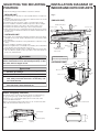
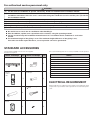
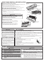
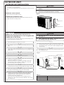
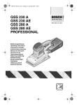
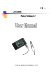
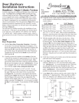
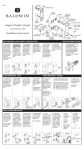
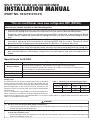
SPLIT TYPE ROOM AIR CONDITIONER
INSTALLATION MANUAL
(PART NO. 9312791019-01)
This air conditioner uses new refrigerant HFC (R410A).
The basic installation work procedures are the same as conventional refrigerant (R22) models.
However, pay careful attention to the following points:
(1) Since the working pressure is 1.6 times higher than that of conventional refrigerant(R22) models,
some of the piping and installation and service tools are special.(See the table below.)
Especially, when replacing a conventional refrigerant(R22) model with a new refrigerant R410A
model, always replace the conventional piping and flare nuts with the R410A piping and flare
nuts.
(2) Models that use refrigerant R410A have a different charging port thread diameter to prevent
erroneous charging with conventional refrigerant(R22) and for safety. Therefore, check
beforehand.[The charging port thread diameter for R410A is 1/2 threads per inch.]
(3) Be more careful that foreign matter (oil, water, etc.) does not enter the piping than with refrigerant
(R22) models. Also, when storing the piping ,securely seal the opening by pinching ,taping, etc.
(4) When charging the refrigerant, take into account the slight change in the composition of the
gas and liquid phases, and always charge from the liquid phase side whose composition is
stable.
Special tools for R410A
Tool name
Gauge manifold
Charge hose
Vacuum pump
Gas leakage detector
Contents of change
Pressure is high and cannot be measured with a conventional gauge. To prevent erroneous
mixing of other refrigerants, the diameter of each port has been changed.
It is recommended the gauge with seals-0.1 to 5.3 MPa (-1 to 53 bar) for high pressure.
-0.1 to 3.8 MPa (-1 to 38 bar) for low pressure.
To increase pressure resistance, the hose material and base size were changed.
A conventional vacuum pump can be used by installing a vacuum pump adapter.
Special gas leakage detector for HFC refrigerant R410A.
Copper pipes
It is necessary to use seamless copper pipes and it is desirable
Table 1 Thicknesses of Annealed Copper Pipes
that the amount of residual oil is less than 40 mg/10m. Do not
Thickness (mm)
use copper pipes having a collapsed, deformed or discolored
Nominal
Outer diameter
R410A
[ref.] R22
portion (especially on the interior surface). Otherwise, the
diameter
(mm)
expansion value or capillary tube may become blocked with
1/4
6.35
0.80
0.80
contaminants.
3/8
9.52
0.80
0.80
As an air conditioner using R410A incurs pressure higher than
when using R22, it is necessary to choose adequate materials.
Thicknesses of copper pipes used with R410A are as shown in Table1.Never us copper pipes thinner than 0.8mm even
when it is available on the market.
WARNING
(1) Do not use the existing (for R22) piping and flare nuts.
• If the existing materials are used, the pressure inside the refrigerant cycle will rise and cause breakage, injury,
etc.(Use the special R410A materials.)
(2) When installing and relocating the air conditioner, do not mix gases other than the specified refrigerant(R410A)
to enter the refrigerant cycle.
• If air or other gas enters the refrigerant cycle, the pressure inside the cycle will rise to an abnormally high value
and cause breakage, injury, etc.
SELECTING THE MOUNTING
POSITION
INSTALLATION DIAGRAM OF
INDOOR AND OUTDOOR UNITS
Decide the mounting position with the customer as follows:
1. INDOOR UNIT
Fig. 2
(1) Install the indoor unit level on a strong wall which is not subject to
vibration.
(2) The inlet and outlet ports should not be obstructed : the air should
be able to blow all over the room.
(3) Install the unit near an electric outlet or special branch circuit.
(4) Do not install the unit where it will be exposed to direct sunlight.
(5) Install the unit where connection to the outdoor unit is easy.
(6) Install the unit where the drain pipe can be easily installed.
(7) Take servicing, etc. into consideration and leave the spaces shown
in (Fig. 2). Also install the unit where the dustbox and the filter can
be removed.
[INDOOR UNIT]
Wall hook bracket
6.7 cm or
over
6.5 cm or over
5 cm or over
2. OUTDOOR UNIT
Front panel
(1) If possible, do not install the unit where it will be exposed to direct
sunlight. (If necessary, install a blind that does not interfere with
the air flow.)
(2) Do not install the unit where a strong wind blows or where it is very
dusty.
(3) Do not install the unit where people pass.
(4) Take you neighbors into consideration so that they are not disturbed
by air blowing into their windows or by noise.
(5) Provide the space shown in Fig. 2 so that the air flow is not blocked.
Also for efficient operation, leave open three of the four directions
front, rear, and both sides.
WARNING
(2)
(3)
(4)
230 cm or
over
*The filters come out
of the front of the
indoor unit.
Remote
control unit
holder
Connection Cord
Install at a place that can withstand the weight of the
indoor and outdoor units and install positively so that
the units will not topple or fall.
(1)
Indoor unit
housing
(Wall cap)
Remote
control unit
150 cm or over
CAUTION
Do not install where there is the danger of combustible gas leakage.
Do not install near heat sources.
If children under 10 years old may approach the
unit, take preventive measures so that they cannot reach the unit.
Install the indoor unit on the wall where the height
from the floors more than 230 cm.
Conform to Type245 IEC57
10 cm or over
[OUTDOOR UNIT]
60 cm or over
10 cm or over
30 cm or
over
30 cm or over
[Indoor unit piping direction]
The piping can be connected in the five directions indicated by 1,
2, 3, 4, and 5 in (Fig. 1). When the piping is connected in
direction 2 or 5, cut along the piping groove in the side of the
front cover with a hacksaw.
When connecting the piping in direction 3, cut a notch in the thin
wall at the front bottom of the front cover.
Fig. 3
6Left piping
1Right piping
5Left-rear piping
3Rear piping
2Bottom piping
4Left-bottom
piping
Drain hose
54 cm
32 cm
Fig. 1
Outdoor unit bottom
INDOOR UNIT
CUTTING THE HOLE IN THE WALL FOR THE CONNECTING PIPING
(1) Cut a 65 mm diameter hole in the wall at the position shown in (Fig.
4).
(2) When cutting the wall hole at the inside of the installation frame, cut
the hole within the range of the left and right center marks 40 mm
below the installation frame.
When cutting the wall hole at the outside of the installation frame,
cut the hole at least 10 mm below over.
(3) Cut the hole so that the outside end is lower (5 to 10 mm) than the
inside end.
(4) Always align the center of the wall hole. If misaligned, water leakage
will occur.
(5) Cut the wall pipe to match the wall thickness, stick it into the wall cap,
fasten the cap with vinyl tape, and stick the pipe through the hole.
(The connection pipe is supplied in the installation set.) (Fig. 4)
(6) For left piping and right piping, cut the hole a little lower so that drain
water will flow freely. (Fig. 4)
Fig. 4
Centering marks
Wall hook bracket
Lower
Lower
65 mm hole
65 mm hole
10 mm or
over
Fasten with
vinyl tape
(Wall pipe)
(Wall cap)
(Inside)
Wall
(Outside)
INSTALLING THE WALL HOOK BRACKET
(1) Install the wall hook bracket so that it is correctly positioned horizontally and vertically. If the wall hook bracket is tiled, water will drip to
the floor.
(2) Install the wall hook bracket so that it is strong enough to withstand
the weight of an adult.
● Fasten the wall hook bracket to the wall with 8 or more screws through
the holes near the outer edge of the bracket.
● Check that there is no rattle at the wall hook bracket.
Fig. 5
Wall hook bracket
Leveling method
WARNING
Tapping screw
(size: large; quantity: 8)
If the wall pipe is not used, the cord interconnecting
the indoor and outdoor units may touch metal and
cause electric leakage.
CAUTION
Hang weight
from here.
Wall hook
bracket
Install the wall hook bracket horizontally and
perpendicularly.
Weight
String
FORMING THE DRAIN HOSE AND PIPE
[Rear piping, Right piping, Bottom piping]
●
●
●
Fig. 6
Install the indoor unit piping in the direction of the wall hole and bind
the drain hose and pipe together with vinyl tape. (Fig. 6)
Install the piping so that the drain hose is at the bottom.
Wrap the pipes of the indoor unit that are visible from the outside
with decorative tape.
Right outlet
[For Left rear piping, Left piping]
Piping (on top)
Interchange the drain cap and the drain hose.
Rear outlet
CAUTION
Bottom outlet
After removing the drain hose, do not forget to install
the drain cap.
Drain hose (on bottom)
Bind with vinyl tape
For left outlet
piping, cut off the
piping outlet
cutting groove
with a hacksaw.
Indoor unit
drain hose
Drain cap
Drain hose
Insert the drain cap and drain hose
until it butts against the drain port.
Drain cap
Remove the drain
cap by pulling at
the projection at
the end of the cap
with pliers, etc.
●
●
●
For left piping and left rear piping, align the marks on the wall hook
bracket and shape the connection pipe.
Bend the connection piping at the bend radius of 70 mm or more and
install no more than 35 mm from the wall.
After passing the indoor piping and drain hose through the wall hole,
hang the indoor unit on the hooks at the top and bottom of the wall
hook bracket.
Fig. 7
Wall hook bracket
Connection piping
Alignment marks
[Installing the indoor unit]
●
●
Small piping
Hang the indoor unit from the hooks at the top of the wall hook bracket.
Insert the spacer, etc. between the indoor unit and the wall hook
bracket and separate the bottom of the indoor unit from the wall.
Indoor unit
Large piping
Upper hooks
Indoor unit
(Spacer)
Lower slots
(Lower projections)
After hooking the indoor unit to the top hook, hook the fittings of the
indoor unit to the two bottom hooks while lowering the unit and
pushing it against the wall.
Wall hook bracket
CONNECTING THE PIPING
Fig. 8
Tighten with two wrenches.
CONNECTION
(1) Install the outdoor unit wall cap (supplied with the optional installation set
or procured at the site) to the wall pipe.
(2) Connect the outdoor unit and indoor unit piping.
(3) After matching the center of the flare surface and tightening the nut hand
tight, tighten the nut to the specified tightening torque with a torque wrench.
(Table 2)
FLARING
Wrench (fixed)
Flare nut
Torque
wrench
Indoor unit pipe
(1) Cut the connection pipe to the necessary
length with a pipe cutter.
(2) Hold the pipe downward so that cuttings
will not enter the pipe and remove the
burrs.
(3) Insert the flare nut onto the pipe and flare
the pipe with a flaring tool.
Insert the flare nut (always use the flare nut
attached to the indoor and outdoor units
respectively) onto the pipe and perform the
flare processing with a flare tool.
Use the special R410A flare tool, or the conventional (for R22) flare tool.
When using the conventional flare tool, always
use an allowance adjustment gauge and secure
the A dimension shown in table 3 .
Check if [L] is flared uniformly
and is not cracked or scratched.
Table 2
6.35 mm dia.
9.52 mm dia.
A
ø 6.35 mm (1/4”)
ø 9.52 mm (3/8”)
Pipe
Tightening torque
15.7 to 17.6 N•m
(160 to 180 kgf•cm)
29.4 to 41.1 N•m
(300 to 420 kgf•cm)
Tightening torque standard
(using a 20 cm wrench)
Wrist strength
Arm strength
Pipe outside diameter
Pipe outside
diameter
Die
To prevent gas leakage, coat the flare
surface with refrigerator oil.
Flare nut tightening torque
Flare nut
Table 3
Connection pipe
A (mm)
Conventional (R22) flare tool
Flash tool for
R410A, clutch type
Clutch type
Wing nut type
0 to 0.5
0 to 0.5
1.0 to 1.5
1.0 to 1.5
1.5 to 2.0
1.5 to 2.0
INDOOR UNIT WIRING
(1)
(2)
(3)
(4)
Open the front panel.
Remove the front cover.
Remove the cord clamp.
Route the connection cord from behind the indoor unit.
(5) Connect the end of the connection cord securely to the terminal block.
(6) Secure the connection cord with the cord clamp.
(7) Install the front cover with the screw.
(8) Close the front panel.
Fig. 9
Screw
Screw
Connection
cord
5 mm
12 mm
Cord clamp
40 mm
35 mm
Cord clamp
5 mm
12 mm
Front panel
Front cover
Screw
Connection
cord
CAUTION
(1) Match the terminal block numbers and connection (3) Always fasten the outside covering of the connection cord with the cord clamp. (If the insulator is
cord colors with those of the outdoor unit.
chafed, electric leakage may occur.)
Erroneous wiring may cause burning of the electric parts.
(4) Securely earth the power cord plug.
(2) Connect the connection cords firmly to the terminal (5) Do not use the earth screw for an external connector.
block. Imperfect installation may cause a fire.
Only use for interconnection between two units.
For authorized service personnel only.
WARNING
(1) For the room air conditioner to operate satisfactory, install it as outlined in this installation manual.
(2) Connect the indoor unit and outdoor unit with the air conditioner piping and cords available standards parts. This
installation manual describes the correct connections using the standard accessories and the parts specified in
this installation manual.
(3) Have installation work done by authorized service personnel only.
(4) Never cut the power cord, lengthen or shorten the cord, or change the plug.
(5) Also do not use an extension cord.
(6) Plug in the power cord plug firmly. If the receptacle is loose, repair it before using the room air conditioner.
(7) Do not turn on the power until all installation work is complete.
● Be careful not to scratch the air conditioner when handling it.
● After installation, explain correct operation to the customer, using the operating manual.
● Let the customer keep this installation manual because it is used when the air conditioner is serviced or
moved.
● The maximum length of the piping is 15 m. The maximum height difference of the piping is 8 m,
if the units are further apart than these, correct operation can not be guaranteed.
STANDARD ACCESSORIES
The following installation accessories are supplied.
Use them as required.
Name and Shape
Q’ty
Name and Shape
One set of following parts are necessary in istallation of this product.
Connection pipe assembly
Drain pipe
Wall hook bracket
Name
Q’ty
Connection cord
Wall pipe
1
1
Decorative tape
Vinyl tape
Wall cap
Saddle
Drain hose
Cloth tape
Remote
control
unit
Tapping screws
Sealant
1
1
ELECTRICAL REQUIREMENT
Battery
Always make the air conditioner power supply a special branch circuit
and provide a special switch and receptacle. Do not extend the power
cord.
Tapping screw(big)
( 4x20)
2
Remote control unit
holder
8
Tapping screw(small)
1
2
FRONT PANEL REMOVAL AND INSTALLATION
REMOVING THE INDOOR UNIT HOUSING
Fig. 20
(1) Remove the two screw caps, and then remove the two lower tapping screws.
(2) Open the front panel, and then remove the front cover.
(3) Remove the four upper tapping screws.
(Note: One tapping screw is located behind the front cover.)
(4) Unhook the indoor unit housing from the center projection and remove.
Indoor unit
housing
INSTALLING THE INDOOR UNIT HOUSING
(1) Insert the six tabs on the indoor unit housing into the indoor unit.
(2) Hook the indoor unit housing onto the center projection.
(3) Install the six tapping screws (both upper and lower), and then install the
screw caps.
(4) Install the front cover with the screw.
Lower tapping
screws Upper tapping screws
Screw caps
Indoor unit
housing
Note: Install the indoor unit housing with the front panel closed.
Screw
Center
projection Front cover
Intake grille
CAUTION
Install the indoor unit housing securely.
If the indoor unit housing is not installed securely, it
could fall and cause personal injury.
Tabs
REMOVING THE DUST BOXES
(1) Open the two latches on the ends of each dust box.
(2) Remove the dust boxes with the air filters attached.
Latches
Latches
Indoor unit
housing
INSTALLING THE DUST BOXES
(1) Install the dust boxes with the air filters attached.
(2) Close the two latches on the ends of each dust box.
(The latches will "click" when they are closed.)
Air filter
Dust box
CAUTION
Install the front panel and intake
grille securely. If installation is
imperfect, the front panel or intake
grille may fall off and cause injury.
Be sure that the top hole of the front
panel is hooked securely to the hook
of the base.
CUSTOMER GUIDANCE
Explain the following to the customer in
accordance with the operating manual:
(1) Starting and stopping method, operation
switching, temperature adjustment,
timer, air flow switching, and other
remote control unit operations.
(2) Dustbox filter, air filter and top grill
removal and cleaning, and how to use
the air louvers.
(3) Give the operating and installation
manuals to the customer.
TEST RUNNING
● Perform test operation and check items 1 and 2 below.
● For the test operation method, refer to the operating manual.
● The outdoor unit, may not operate, depending on the room temperature. In this case, press
the test run button on the remote control unit while the air conditioner is running, (Point the
transmitter section of the remote control unit toward the air conditioner and press the test
run button with the tip of a ball-point pen, etc.)
● To end test operation, press the remote control unit START/STOP button.
(When the air conditioner is run by pressing the test run button, the OPERATION indicator
lamp and TIMER indicator lamp will simultaneously flash slowly.)
1. INDOOR UNIT
(1)
(2)
(3)
(4)
Fig. 17
Is operation of each button on the remote control unit normal?
Does each lamp light normally?
Do the air flow-direction louver operate normally?
Is the drain normal?
Transmitter section
2. OUTDOOR UNIT
(1) Is there any abnormal noise and vibration during operation?
(2) Will noise, wind, or drain water from the unit disturb the
neighbors?
(3) Is there any gas leakage?
Test run button
POWER
WARNING
(1)
(2)
(3)
(4)
(5)
(6)
(7)
The rated voltage of this product is 230 V AC 50 Hz.
Before turning on the power, check if the voltage is within
the 220 V -10 % to 240 V +10 % range.
Always use a special branch circuit and install a special
receptacle to supply power to the room air conditioner.
Use a circuit breaker and receptacle matched to the
capacity of the air conditioner.
Do not extend the power cord.
Perform wiring work in accordance with standards so that
the air conditioner can be operated safely and positively.
Install a leakage circuit breaker in accordance with the
related laws and regulations and electric company
standards.
CAUTION
(1)
The power source capacity must be the sum of the air conditioner
current and the current of other electrical appliances. When the
current contracted capacity is insufficient, change the contracted
capacity.
(2)
When the voltage is low and the air conditioner is difficult to start,
contact the power company the voltage raised.
NOTE: These equipment shall be connected to a suitable mains network with a
main impedance less than the following: 1. 257Ω
The product is intended for use only in premises having a service current
capacity 100A per phase,supplied from a distribution network having a
nominal voltage of 230 V, and instruct the user to determine in consulation
with the supply authority, if necessary, that the service current capacity at
the interface point is sufficient for the equipment.
OUTDOOR UNIT
OUTDOOR UNIT INSTALLATION
●
●
Set the unit on a strong stand, such as one made of concrete blocks
to minimize shock and vibration.
Do not set the unit directly on the ground because it will cause trouble.
WARNING
(1) Install the unit where it will not be tilted by mor
than 5°.
(2) When installing the outdoor unit where it may ex
posed to strong wind, fasten it securely.
Connector cover removal
●
Remove the two mounting screws.
Fig. 10
Installing the connector cover
(1) After inserting the three front hooks, then insert the rear hook.
(2) Tighten the two mounting screws.
Tapping screw
Tabs
Electrical cover
AIR PURGE
CAUTION
Always use a vacuum pump to purge the air.
Refrigerant for purging the air is not charged in the
outdoor unit at the factory.
(1) Refrigerant must not be discharged into
atmosphere.
Close the high pressure side valve of the gauge manifold fully and do
not operate it during the following work.
(2) After connecting the piping , check the joints fo
gas leakage with gas leak detector.
1. Check if the piping connections are secure.
2. Check that the stems of 2-way valve and 3-way valve are closed
fully.
10. Fully open the valve stems of the 2-way valve and 3-way valv
using a hexagon wrench. (After the valve stem begins to turn
turn it with a torque of less than 2.9 N•m (30 kgf•cm) until
stops turning.)
3. Connect the gauge manifold charge hose to the charging port
of the 3-way valve (side with the projection for pushing in the
valve core).
11. Firmly tighten the 2-way valve and 3-way valve blank cap an
the charging port cap.
4. Open the low pressure side valve of the gauge manifold fully.
Fig. 11
5. Operate the vacuum pump and start pump down.
3-way valve
Gauge manifold
Compound pressure gauge
Pressure ga
-0.1 MPa
2-way valve
(-76 cmHg
Flare nut
-1 bar)
High
pressu
Low pressure
side v
side valve
(close
LO
HI
6. Slowly loosen the flare nut of the 3-way valve and check if air
enters, then retighten the flare nut.
(When the flare nut is loosened the operating sound of the
vacuum pump changes and the reading of the compound
pressure gauge goes from minus to zero.)
Valve stem
7. Pump down the system for at least 15 minutes, then check if the
compound pressure gauge reads -0.1 MPa (-76 cmHg, -1 bar).
8. At the end of pump down, close the low pressure side gauge of
the gauge manifold fully and stop the vacuum pump.
9. Slowly loosen the valve stem of the 3-way valve. When the
compound pressure gauge reading reaches 0.1-0.2 MPa,
retighten the valve stem and disconnect the charge hose
from the 3-way valve charging port.
(If the stem of the 3-way valve is opened fully before the
charge hose is disconnected, it may be difficult to disconnect
the charge hose.)
Blank cap
Charge hose
Charging port
Charging port cap
Charge
hose
Vacuum pu
Table 4
Tightening torque
Blank cap
19.6 to 24.5 N•m (200 to 250 kgf•cm)
Charging port cap
12.3 to 15.7 N•m (125 to 160 kgf•cm)
OUTDOOR UNIT WIRING
(5) Fasten the sheath with a cord clamp.
(6) Install the control box cover.
(7) Install the connector cover.
5mm
Remove the outdoor unit connector cover.
Remove the control box cover.
Bend the end of the cord as shown in the figure.
Connect the end of the connection cord fully into the terminal block.
12mm
(1)
(2)
(3)
(4)
Fig. 12
5mm
50mm
Control box cover
25mm
Earth screw
12mm
Control box
Cord clamp
Sheath
Cord clamp
Earth screw
Indoor unit terminal block
Earth screw
Outdoor unit terminal block
Connection cord
Connector cord
Fig. 13
Connection cord wiring
Control box cover
Run the connection cord to the rear of the outdoor unit within the range
of the arrows shown in the figure.
(The connector cover becomes difficult to install.)
Connector cord
CAUTION
(1) Match the terminal block numbers and connection (3) Always fasten the outside covering of the connection cord with the cord clamp. (If the insulator is
cord colors with those of the indoor unit.
chafed, electric leakage may occur.)
Erroneous wiring may cause burning of the electric
parts.
(4) Securely earth the power cord plug.
(2) Connect the connection cords firmly to the terminal (5) Do not use the earth screw for an external connector.
block. Imperfect installation may cause a fire.
Only use for interconnection between two units.
FINISHING
(1) Insulate between pipes.
● For rear, right, and bottom piping, overlap the connection pipe heat insulation and
indoor unit pipe heat insulation and bind them with vinyl tape so that there is no gap.
● For left and left rear piping, butt the connection pipe heat insulation and indoor unit
pipe heat insulation together and bind them with and vinyl tape so that there is no gap.
● For left and left rear piping, wrap the area which accommodates the rear piping housing
section with cloth tape.
● For left and left rear piping, bind the connection cord to the top of the pipe with vinyl
tape.
● For left and left rear piping, bundle the piping and drain hose together by wrapping
them with cloth tape over the range within which they fit into the rear piping housing
section.
(2) Temporarily fasten the connection cord along the connection pipe with vinyl tape. (Wrap
to about 1/3 the width of the tape from the bottom of the pipe so that water does not
enter.)
(3) Fasten the connection pipe to the outside wall with saddles, etc.
(4) Fill the gap between the outside wall pipe hole and the pipe with sealer so that rain
water and wind cannot blow in.
(5) Fasten the drain hose to the outside wall, etc.
Fig. 15
(Outside wall cap)
(Saddle)
(Sealer putty)
Wall
Pipe
(Outdoors)
Fig. 14
Overlap the insulation
Connection pipe
(heat insulation)
Indoor unit pipe
(heat insullation)
Vinyl tape
Bind the pipes together so
that there is no gap.
Pipe
Wrap with cloth tape
Drain hose
Left piping
For connection from the left rear
Connection
cord
Connection piping
Cloth tape
(Wall pipe)
Connection
cord
Drain hose
Drain hose
BAD
BAD
Lifted up
Bent
Connection
piping
BAD
Drain hose
Holder
(Included with the piping
set sold separately or
obtained locally)
Immersed in water