1
+00EH99861901_01EN_Outdoor6HP_IM.book Page 1 Monday, June 2, 2008 6:00 PM
AIR CONDITIONER (SPLIT TYPE)
Installation manual
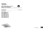
Outdoor Unit
Model name:
RAV-SM1603AT-E
RAV-SM1603ATZ-E
RAV-SM1603ATZG-E
Not accessible to the general public
Vente interdite au grand public
Kein öffentlicher Zugang
Non accessibile a clienti generici
No destinado al público en general
Não acessível ao público em geral
Niet geschikt voor huishoudelijk gebruik
Μη προσβάσιμο από το γενικό κοινό
Недоступен для посторонних
Genel erişime açık değildir
Installation manual
Air conditioner (Split type)
1 English
Manuel d'installation
Climatiseur (Type split)
25 Français
Installations-handbuch
Klimagerät (Split-typ)
49 Deutsch
Manuale di installazione
Condizionatore d’aria (Tipo split)
73 Italiano
Manual de instalación
Aire acondicionado (Tipo split)
97 Español
Manual de Instalação
Ar condicionado (Tipo split)
121 Português
Installatiehandleiding
Airconditioner (Gesplitst type)
145 Nederlands
Εγχειρίδιο εγκατάστασης
Κλιματιστικό (Τύπου Split)
169 Ελληνικά
Руководство по установке
Кондиционер воздуха
(сплит-система)
193 Русский
Montaj Kılavuzu
Klima (Split tip)
217 Türkçe
Toshiba XXXXXXX(<SanSerif1>X/X)
+00EH99861901_01EN_Outdoor6HP_IM.book Page 1 Monday, June 2, 2008 6:00 PM
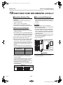
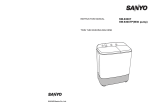
Outdoor Unit Installation Manual
Digital Inverter
Please read this Installation Manual carefully before installing the Air Conditioner.
• This Manual describes the installation method of the outdoor unit.
• For installation of the indoor unit, follow the Installation Manual attached to the indoor unit.
ADOPTION OF NEW REFRIGERANT
This Air Conditioner is a new type which adopts a new refrigerant HFC (R410A) instead of the conventional
refrigerant R22 in order to prevent destruction of the ozone layer.
Contents
1 ACCESSORY PARTS AND REFRIGERANT . . . . . . . . . . . . . . . . . . . . . . . . . . . . . . . . 2
2 PRECAUTIONS FOR SAFETY . . . . . . . . . . . . . . . . . . . . . . . . . . . . . . . . . . . . . . . . . . . 3
3 INSTALLATION OF NEW REFRIGERANT AIR CONDITIONER . . . . . . . . . . . . . . . . . 4
4 SELECTION OF INSTALLATION . . . . . . . . . . . . . . . . . . . . . . . . . . . . . . . . . . . . . . . . . 6
5 REFRIGERANT PIPING . . . . . . . . . . . . . . . . . . . . . . . . . . . . . . . . . . . . . . . . . . . . . . . . 11
6 AIR PURGING . . . . . . . . . . . . . . . . . . . . . . . . . . . . . . . . . . . . . . . . . . . . . . . . . . . . . . . 14
7 ELECTRICAL WORK . . . . . . . . . . . . . . . . . . . . . . . . . . . . . . . . . . . . . . . . . . . . . . . . . . 16
8 EARTHING . . . . . . . . . . . . . . . . . . . . . . . . . . . . . . . . . . . . . . . . . . . . . . . . . . . . . . . . . . 20
9 FINISHING . . . . . . . . . . . . . . . . . . . . . . . . . . . . . . . . . . . . . . . . . . . . . . . . . . . . . . . . . . 20
10 TEST RUN . . . . . . . . . . . . . . . . . . . . . . . . . . . . . . . . . . . . . . . . . . . . . . . . . . . . . . . . . . 20
11 ANNUAL MAINTENANCE . . . . . . . . . . . . . . . . . . . . . . . . . . . . . . . . . . . . . . . . . . . . . . 20
12 FUNCTIONS TO BE IMPLEMENTED LOCALLY . . . . . . . . . . . . . . . . . . . . . . . . . . . . 21
13 TROUBLESHOOTING . . . . . . . . . . . . . . . . . . . . . . . . . . . . . . . . . . . . . . . . . . . . . . . . . 22
14 APPENDIX . . . . . . . . . . . . . . . . . . . . . . . . . . . . . . . . . . . . . . . . . . . . . . . . . . . . . . . . . . 23
1-EN
–1–
Toshiba XXXXXXX(<SanSerif1>X/X)
+00EH99861901_01EN_Outdoor6HP_IM.book Page 2 Monday, June 2, 2008 6:00 PM
Outdoor Unit Installation Manual
Digital Inverter
1
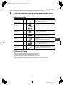
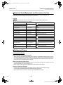
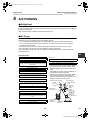
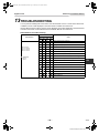
ACCESSORY PARTS AND REFRIGERANT
Accessory parts
Part name
Q’ty
Shape
Usage
Outdoor unit
Installation manual
1
Drain nipple
1
Waterproof rubber cap
5
Protective bush
1
For protecting wires (pipe cover)
Guard material for passage
part
1
For protecting passage part (pipe cover)
Ferrite core
1
For conforming to EMC standards for twin/triple systems
Color: White
(Used for indoor/outdoor connecting wires)
Clamp filter
1
For conforming to EMC standards for twin/triple systems
Color: Gray
(Used for outdoor fan motor lead wire)
Banding band
2
For conforming to EMC standards for twin/triple systems
(For clamping the clamp filter and ferrite core)
(Hand this directly to the customer.)
EN
Refrigerant Piping
• Piping kit used for the conventional refrigerant cannot be used.
• Use copper pipe with 0.8 mm or more thickness for Ø9.5 mm.
Use copper pipe with 1.0 mm or more thickness for Ø15.9 mm.
• Flare nut and flare works are also different from those of the conventional refrigerant.
Take out the flare nut attached to the air conditioner, and use it.
–2–
2-EN
Toshiba XXXXXXX(<SanSerif1>X/X)
+00EH99861901_01EN_Outdoor6HP_IM.book Page 3 Monday, June 2, 2008 6:00 PM
Outdoor Unit Installation Manual
Digital Inverter
2
PRECAUTIONS FOR SAFETY
• Ensure that all Local, National and International regulations are satisfied.
• Read this “PRECAUTIONS FOR SAFETY” carefully before Installation.
• The precautions described below include the important items regarding safety.
Observe them without fail.
• After the installation work, perform a trial operation to check for any problem.
Follow the Owner’s Manual to explain how to use and maintain the unit to the customer.
• Turn off the main power supply switch (or breaker) before the unit maintenance.
• Ask the customer to keep the Installation Manual together with the Owner’s Manual.
WARNING
• Ask an authorized dealer or qualified installation professional to install/maintain the air conditioner.
Inappropriate installation may result in water leakage, electric shock or fire.
• Be sure to connect earth wire. (grounding work)
Incomplete grounding cause an electric shock.
Do not connect ground wires to gas pipes, water pipes, lightning rods or ground wires for telephone wires.
• Turn off the main power supply switch or breaker before attempting any electrical work.
Make sure all power switches are off. Failure to do so may cause electric shock.
Use an exclusive power circuit for the air conditioner. Use the rated voltage.
• Connect the connecting wire correctly.
If the connecting wire is connected in a wrong way, electric parts may be damaged.
• When moving the air conditioner for the installation into another place, be very careful not to enter
any gaseous matter other than the specified refrigerant into the refrigeration cycle.
If air or any other gas is mixed in the refrigerant, the gas pressure in the refrigeration cycle becomes
abnormally high and it may resultingly causes pipe burst and injuries on persons.
• Do not modify this unit by removing any of the safety guards or by by-passing any of the safety
interlock switches.
• After unpacking the unit, examine it carefully if there are possible damage.
• Do not install in a place that might increase the vibration of the unit.
• To avoid personal injury (with sharp edges), be careful when handling parts.
• Perform installation work properly according to the Installation Manual.
Inappropriate installation may result in water leakage, electric shock or fire.
• When the air conditioner indoor unit is installed in a small room, provide appropriate measures to
ensure that the concentration of refrigerant leakage occur in the room does not exceed the critical
level.
• Tighten the flare nut with a torque wrench in the specified manner.
Excessive tightening of the flare nut may cause a crack in the flare nut after a long period, which may result
in refrigerant leakage.
• Wear heavy gloves during the installation work to avoid injury.
• Install the air conditioner securely in a location where the base can sustain the weight adequately.
• Perform the specified installation work to guard against an earthquake.
If the air conditioner is not installed appropriately, accidents may occur due to the falling unit.
• If refrigerant gas has leaked during the installation work, ventilate the room immediately.
If the leaked refrigerant gas comes in contact with fire, noxious gas may generate.
• After the installation work, confirm that refrigerant gas does not leak.
If refrigerant gas leaks into the room and flows near a fire source, such as a cooking range, noxious gas
might generate.
• Electrical work must be performed by a qualified electrician in accordance with the Installation
Manual. Make sure the air conditioner uses an exclusive power supply.
An insufficient power supply capacity or inappropriate installation may cause fire.
• Use the specified wires for wiring connect the terminals securely fix.
To prevent external forces applied to the terminals from affecting the terminals.
3-EN
–3–
Toshiba XXXXXXX(<SanSerif1>X/X)
+00EH99861901_01EN_Outdoor6HP_IM.book Page 4 Monday, June 2, 2008 6:00 PM
Outdoor Unit Installation Manual
Digital Inverter
WARNING
• When the air conditioner cannot cool or heat a room well, contact the dealer from whom you
purchased the air conditioner as refrigerant leakage is considered as the cause.
In the case of repair that requires refill of refrigerant, ask service personnel about details of the
repair.
The refrigerant used in the air conditioner is harmless.
Generally, the refrigerant does not leak. However, if the refrigerant leaks in a room and a heater or stove
burner in the room catches fire, it may generate toxic gas.
When you ask service personnel for repairing refrigerant leakage, confirm that the leakage portion has
been completely repaired.
• Conform to the regulations of the local electric company when wiring the power supply.
Inappropriate grounding may cause electric shock.
• Do not install the air conditioner in a location subject to a risk of exposure to a combustible gas.
If a combustible gas leaks, and stays around the unit, a fire may occur.
• Install the refrigerant pipe securely during the installation work before operating the air
conditioner.
If the compressor is operated with the valve open and without the refrigerant pipe, the compressor sucks
air and the refrigeration cycle is overpressurized, which may cause a burst or injury.
• For the refrigerant recovery work (collection of refrigerant from the pipe to the compressor), stop
the compressor before disconnecting the refrigerant pipe.
If the refrigerant pipe is disconnected while the compressor is working with the valve open, the compressor
sucks air and the refrigeration cycle is overpressurized, which may cause a burst or injury.
EN
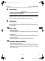
CAUTION
New Refrigerant Air Conditioner Installation
• THIS AIR CONDITIONER ADOPTS THE NEW HFC REFRIGERANT (R410A) WHICH DOES NOT
DESTROY OZONE LAYER.
• The characteristics of R410A refrigerant are ; easy to absorb water, oxidizing membrane or oil, and its
pressure is approx. 1.6 times higher than that of refrigerant R22. Accompanied with the new refrigerant,
refrigerating oil has also been changed. Therefore, during installation work, be sure that water, dust, former
refrigerant, or refrigerating oil does not enter the refrigerating cycle.
• To prevent charging an incorrect refrigerant and refrigerating oil, the sizes of connecting sections of
charging port of the main unit and installation tools are changed from those for the conventional refrigerant.
• Accordingly the exclusive tools are required for the new refrigerant (R410A).
• For connecting pipes, use new and clean piping designed for R410A, and please care so that water or dust
does not enter.
To Disconnect the Appliance from Main Power Supply
• This appliance must be connected to the main power supply by means of a switch with a contact separation
of at least 3 mm.
• The installation fuse 40 A (All type fuse can be used) must be used for the power supply line of this
conditioner.
3
INSTALLATION OF NEW REFRIGERANT
AIR CONDITIONER
• The R410A refrigerant is more susceptible to impurities such as water, oxide membrane, oils, and fats.
With the adoption of the new refrigerant, refrigerating oil has also been changed.
Be careful so that water, dust, conventional refrigerant, and/or conventional refrigerating oil do not
enter the refrigerating cycle of the new refrigerant air conditioner.
• To prevent different refrigerant or refrigerating oil being mixed, the sizes of the charging port of the unit
and the installation tool connecting sections are different from the conventional refrigerant. Accordingly
the following exclusive tools are required for the new refrigerant R410A.
–4–
4-EN
Toshiba XXXXXXX(<SanSerif1>X/X)
+00EH99861901_01EN_Outdoor6HP_IM.book Page 5 Monday, June 2, 2008 6:00 PM
Outdoor Unit Installation Manual
Digital Inverter
Required Tools/Equipment and Precautions for Use
Prepare the tools and equipment listed in the following table before starting installation work.
Newly prepared tools and equipment must be used exclusively.
Legend
: Prepared newly (Use for R410A only. Do not use for refrigerant R22 or R407C etc..)
: Conventional tools/equipment are available
Tools/equipment
Gauge manifold
Use
How to use tools/equipment
Charging hose
Vacuuming/charging
refrigerant and operation
check
Prepared newly for R410A only
Charging cylinder
Can not be used
Gas leak detector
Gas leak check
Vacuum pump with backflow
prevention function
Vacuum drying
Vacuum pump with backflow
prevention function
Vacuum drying
R22 (Conventional tools)
Flare tool
Flare machining of pipes
Usable if dimensions are adjusted.
Bender
Bending pipes
R22 (Conventional tools)
Refrigerant recovery equipment
Refrigerant recovery
For R410A only
Torque wrench
Tightening flare nuts
Exclusive for Ø12.7 mm and Ø15.9 mm
Pipe cutter
Cutting pipes
R22 (Conventional tools)
Refrigerant cylinder
Charging refrigerant
Welding machine and nitrogen
cylinder
Welding pipes
R22 (Conventional tools)
Refrigerant charging measure
Charging refrigerant
R22 (Conventional tools)
Prepared newly for R410A only
Unusable (Use the refrigerant charging measure
instead.)
Prepared newly
Unusable
For R410A only
Discriminated by the refrigerant name on the
cylinder.
Refrigerant Piping
New refrigerant (R410A)
When using the conventional piping kit
• When using the conventional piping kit that has no indication of applicable refrigerant types, be sure to
use it with a wall thickness of 0.8 mm for Ø6.4 mm, Ø9.5 mm, and Ø12.7 mm, and with a wall thickness
of 1.0 mm for Ø15.9 mm. Never use the conventional piping kit with a wall thickness less than these
thicknesses due to insufficient pressure capacity.
When using general copper pipes
• Use general copper pipes with a wall thickness of 0.8 mm for Ø6.4 mm, Ø9.5 mm, and Ø12.7 mm, and
with a wall thickness of 1.0 mm for Ø15.9 mm.
Never use any copper pipes with a wall thickness less than these thicknesses.
Flare nuts and flare machining
• The flare nuts and flare machining are different from those for the conventional refrigerant.
Use the flare nuts supplied with the air conditioner or those for R410A.
• Before performing flare machining, carefully read “REFRIGERANT PIPING”
5-EN
–5–
Toshiba XXXXXXX(<SanSerif1>X/X)
+00EH99861901_01EN_Outdoor6HP_IM.book Page 6 Monday, June 2, 2008 6:00 PM
Outdoor Unit Installation Manual
Digital Inverter
4
SELECTION OF INSTALLATION
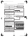
Before installation
Earthing
Be careful to the following items before
installation.
WARNING
Make sure that proper earthing is provided.
Improper earthing may cause electric shock. For
how to check earthing, contact the dealer who
installed the air conditioner or a professional
installation company.
Length of refrigerant pipe
Length of refrigerant
pipe connected to
indoor/outdoor unit
Item
5 m to 30 m
Addition of refrigerant is
unnecessary at the local site.
*31 m to 50 m
<Addition of refrigerant>
Add 40 g of refrigerant for
every 1m of pipe which
exceeds 30 m.
* Caution at addition of refrigerant
When the total length of refrigerant pipe
exceeds 30 m, add 40 g /m of refrigerant and
the maximum total length of pipe is 50 m. (Max.
amount of additional refrigerant is 800 g.)
Charge the refrigerant accurately. Overcharge
may cause a serious trouble of compressor.
* Do not connect a refrigerant pipe shorter than
5 m.
This may cause a malfunction of the
compressor or other devices.
Airtight test
1. Before starting an airtight test, further tighten
the spindle valves on the gas side and liquid
side.
2. Pressurize the pipe with nitrogen gas charged
from the service port to the design pressure
(4.15 Mpa) to conduct the airtight test.
3. After the airtight test is completed, evacuate the
nitrogen gas.
• Proper earthing can prevent charging of
electricity on the outdoor unit surface due to
high frequency of the frequency converter
(inverter) in the outdoor unit, as well as prevent
electric shock. If the outdoor unit is not properly
earthed, you may feel electric shock.
• Be sure to connect earth wire. (grounding
work)
Incomplete grounding cause an electric shock.
Do not connect ground wires to gas pipes, water
pipes, lightning rods or ground wires for
telephone wires.
EN
Test Run
Turn on the leakage breaker at least 12 hours
before starting a test run to protect the
compressor during startup.
CAUTION
Incorrect work may result in a malfunction or
complaints of customers.
Air purge
• For air purge, use a vacuum pump.
• Do not use refrigerant charged in the outdoor
unit for air purge. (The refrigerant for air purge
is not contained in the outdoor unit.)
Electrical wiring
• Be sure to fix the power wires and indoor/
outdoor connecting wires with clamps so that
they do not contact with the cabinet, etc.
–6–
6-EN
Toshiba XXXXXXX(<SanSerif1>X/X)
+00EH99861901_01EN_Outdoor6HP_IM.book Page 7 Monday, June 2, 2008 6:00 PM
Outdoor Unit Installation Manual
Digital Inverter
Installation Place
CAUTION
WARNING
Install the outdoor unit properly at a place that
is durable enough to the weight of the outdoor
unit.
Insufficient durability may cause the outdoor unit
to fall, which may result in injury.
CAUTION
Do not install the outdoor unit at a place
subject to combustible gas leak.
Accumulation of combustible gas around the
outdoor unit may cause a fire.
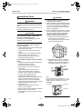
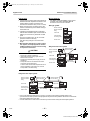
1. Install the outdoor unit at a place where
discharge air is not blocked.
2. When an outdoor unit is installed in a place
that is always exposed to a strong wind like
a coast or on a high storey of a building,
secure a normal fan operation by using a
duct or a wind shield.
3. When installing the outdoor unit in a place
that is constantly exposed to a strong wind
such as the upper stairs or rooftop of a
building, apply the windproof measures
referring to the following examples.
1) Install the unit so that its discharge port
faces to the wall of the building.
Keep a distance 500 mm or more between
the unit and the wall surface.
Install the outdoor unit at a place that meets
the following conditions after customer’s
consent is obtained.
• A well-ventilated place free from obstacles near
the air inlets and air outlet
• A place that is not exposed to rain or direct
sunlight
• A place that does not increase the operating
noise or vibration of the outdoor unit
• A place that does not cause any drainage
problem with discharged water
Do not install the outdoor unit at the following
places.
• A place full of saline atmosphere (coastal area)
or sulfide gas (hot-spring area)
(Special maintenance is required.)
• A place subject to oil, vapor, oily smoke, or
corrosive gas
• A place where organic solvent is used
• A place where high-frequency equipment
(including inverter equipment, private power
generator, medical equipment, and
communication equipment) is used
(Installation in this place may cause malfunction
of the air conditioner, abnormal control or
problems due to noise to such equipment.)
• A place where the discharged air of the outdoor
unit blows against the window of the
neighboring house
• A place where the operating noise of the
outdoor unit is transmitted
• When the outdoor unit is installed in an elevated
position, be sure to secure its feet.
• A place where the drain water does not make
any problem.
7-EN
500
2) Supposing the wind direction during the
operation season of the air conditioner,
install the unit so that the discharge port is
set at right angle to the wind direction.
Strong
wind
Strong
wind
• When using an air conditioner under low outside
temperature condition (Outside temp.:-5 °C or
lower) with COOL mode, prepare a duct or wind
shield so that it is not affected by the wind.
<Example>
Wind shield
Wind shield
Wind shield
–7–
Toshiba XXXXXXX(<SanSerif1>X/X)
+00EH99861901_01EN_Outdoor6HP_IM.book Page 8 Monday, June 2, 2008 6:00 PM
Outdoor Unit Installation Manual
Digital Inverter
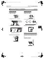
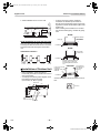
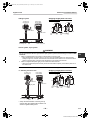
Necessary Space for Installation
(Unit:mm)
Obstacle at front side
▼ Upper side is free
1. Single unit installation
▼ Upper side is free
1. Single unitIn installation
500
or more
150
or more
Obstacle at rear side
200
or more
2. Obstacles at both right and left sides.
2. Serial installation of two or more units
300
or more
3. Serial installation of two or more units
▼ Obstacle also at the upper side
1000
or more
150
or more
1000
or more
The height of the
obstacle should be
lower than the height
of the outdoor unit.
200 or more
1000
or more
150
or more
300
or more
300
or more
300
or more
The height of the obstacle should be lower
than the height of the outdoor unit.
Obstacles at both front and rear sides
Open the upper side and both right and left sides.
The height of obstacle at both front and rear side,
should be lower than the height of the outdoor
unit.
▼ Obstacle also at the upper side
150
or more
150
or more
▼ Standard installation
1. Single unit installation
1000
or more
500
or more
EN
–8–
8-EN
Toshiba XXXXXXX(<SanSerif1>X/X)
+00EH99861901_01EN_Outdoor6HP_IM.book Page 9 Monday, June 2, 2008 6:00 PM
Outdoor Unit Installation Manual
Digital Inverter
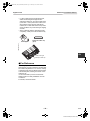
300
or more
300
or more
1000
or more
200
or more
2. Serial installation of two or more units
Serial installation at front and rear sides
Open the upper side and both right and left sides.
The height of obstacle at both front and rear sides
should be lower than the height of the outdoor
unit.
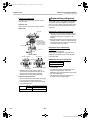
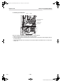
• As shown in the figure below, install the
foundation and vibration-proof rubbers to
directly support the bottom surface of the fixing
leg that is in contact with the bottom plate of the
outdoor unit.
* When installing the foundation for an outdoor
unit with downward piping, consider the piping
work.
GOOD
Absorb vibration
with vibrationproof rubbers
Fixing leg
Foundation
GOOD
Bottom plate
of outdoor unit
▼ Standard installation
Foundation
1000
or more
300
or more
1500
or more
2000
or more
200
or more
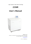
Installation of Outdoor Unit
• Before installation, check strength and
horizontality of the base so that abnormal sound
does not generate.
• According to the following base diagram, fix the
base firmly with the anchor bolts.
(Anchor bolt, nut: M10 x 4 pairs)
Drain hole
525
600
150
If only the end of the
fixing leg is
supported, it may be
deformed.
NO GOOD
Do not support
the outdoor unit
only with the
fixing leg.
Foundation
Set the out margin of the anchor bolt to 15 mm or
less.
15 or less
400
365
45
150
Support the bottom surface of
the fixing leg in contact with
the bottom plate of the outdoor
unit.
Drain
nipple mounting hole
Drain hole
9-EN
–9–
Toshiba XXXXXXX(<SanSerif1>X/X)
+00EH99861901_01EN_Outdoor6HP_IM.book Page 10 Monday, June 2, 2008 6:00 PM
Outdoor Unit Installation Manual
Digital Inverter
• In case of drainning through the drain hose,
attach the following drain nipple and the
waterproof rubber cap, and use the drain hose
(Inner diam.: 16 mm) sold on the market. And
also seal the screws securely with silicone
material, etc. so that water does not drop down.
Some conditions may cause dewing or dripping
of water.
• When collectively draining discharged water
completely, a drain pan must be made locally.
Drain nipple
Waterproof rubber cap
(5pcs.)
EN
Drain nipple
Waterproof rubber cap
For Reference
If a heating operation would be continuously
performed for a long time under the condition that
the outdoor temperature is 0 °C or lower, draining
of defrosted water may be difficult due to freezing
of the bottom plate, resulting in a trouble of the
cabinet or fan.
It is recommended to procure an anti-freeze
heater locally for a safety installation of the air
conditioner.
For details, contact the dealer.
– 10 –
10-EN
Toshiba XXXXXXX(<SanSerif1>X/X)
+00EH99861901_01EN_Outdoor6HP_IM.book Page 11 Monday, June 2, 2008 6:00 PM
Outdoor Unit Installation Manual
Digital Inverter
5
REFRIGERANT PIPING
Knockout of Pipe Cover
Optional Installation Parts
(Local Procure)
Parts name
Q’ty
Refrigerant piping
A Liquid side : Ø9.5 mm
Gas side : Ø15.9 mm
B
Rear direction
Pipe cover
Side direction
Each one
Pipe insulating material
(polyethylene foam, 10 mm thick)
C Putty, PVC tapes
1
Each one
Refrigerant Piping
Connection
Front direction
CAUTION
Down direction
Knockout procedure
• The indoor/outdoor connecting pipes can be
connected to 4 directions.
Take off the knockout part of the pipe cover in
which pipes or wires pass through the base
plate.
• Detach the piping cover and give an impact on
the knockout section a few times with the shank
of a screwdriver. A knockout hole can easily be
punched.
• After punching the knockout hole, remove burrs
of the hole and then install the supplied
protective bush and guard material for passage
part to protect wires and pipes.
Be sure to attach the pipe covers after pipes
have been connected. Cut the slits under the
pipe covers to facilitate the installation.
After connecting the pipes, be sure to mount the
pipe cover. The pipe cover is easily mounted by
cutting off the slit at the lower part of the pipe
cover.
TAKE NOTICE THESE IMPORTANT
4 POINTS BELOW FOR PIPING WORK
1. Keep dust and moisture away from inside
the connecting pipes.
2. Tightly connect the connection between
pipes and the unit.
3. Evacuate the air in the connecting pipes
using VACUUM PUMP.
4. Check gas leak at connected points.
▼ Piping connection
Liquid side
Outer
diameter
Ø9.5 mm
Gas side
Thickness
Outer
diameter
Thickness
0.8 mm
Ø15.9 mm
1.0 mm
Flaring
1. Cut the pipe with a pipe cutter.
Be sure to remove burrs that may cause gas
leak.
2. Insert a flare nut into the pipe, and then flare
the pipe.
Use the flare nuts supplied with the air
conditioner or those for R410A.
Insert a flare nut into the pipe, and flare the
pipe.
As the flaring sizes of R410A differ from those
of refrigerant R22, the flare tools newly
manufactured for R410A are recommended.
* Be sure to wear heavy work gloves while
working.
11-EN
– 11 –
Toshiba XXXXXXX(<SanSerif1>X/X)
+00EH99861901_01EN_Outdoor6HP_IM.book Page 12 Monday, June 2, 2008 6:00 PM
Outdoor Unit Installation Manual
Digital Inverter
However, the conventional
tools can be used by
adjusting projection margin
of the copper pipe.
B
▼ Projection margin in flaring : B (Unit : mm)
Rigid (Clutch type)
Outer diam. of
copper pipe
9.5
R410A tool
used
R410A
0 to 0.5
15.9
Conventional
tool used
1.0 to 1.5
▼ Flaring diam. meter size : A (Unit : mm)
Outer diam. of copper
pipe
A+0 ~ A–0.4
9.5
13.2
15.9
19.7
* In case of flaring for R410A with the
conventional flare tool, pull it out
approx.
0.5 mm more than that for R22 to
adjust to the specified flare size.
The copper pipe gauge is useful for
adjusting projection margin size.
Tightening of Connecting
Part
1. Align the centers of the connecting pipes and
fully tighten the flare nut with fingers. Then fix
the nut with a spanner as shown in the figure
and tighten it with a torque wrench.
2. As shown in the figure, be sure to use two
spanners to loosen or tighten the flare nut of the
valve on the gas side. If you use a single
spanner, the flare nut cannot be tightened to
the required tightening torque.
On the other hand, use a single spanner to
loosen or tighten the flare nut of the valve on
the liquid side.
(Unit: N•m)
Outer dia. of copper
pipe
Tightening torque
9.5 mm (diam.)
33 to 42 (3.3 to 4.2 kgf•m)
15.9 mm (diam.)
68 to 82 (6.8 to 8.2 kgf•m)
Half union or packed valve
Flare nut
A
EN
Externally
threaded side
Internally
threaded side
Fix with spanner.
Tighten with torque wrench.
Cover
Cap
Piping valve
Loosened
Tightened
Flare nut
Valve at gas side
– 12 –
12-EN
Toshiba XXXXXXX(<SanSerif1>X/X)
+00EH99861901_01EN_Outdoor6HP_IM.book Page 13 Monday, June 2, 2008 6:00 PM
Outdoor Unit Installation Manual
Digital Inverter
• Pressure of R410A is higher than that of R22
(Approx. 1.6 times).
Therefore, using a torque wrench, tighten the
flare pipe connecting sections which connect
the indoor/outdoor units at the specified
tightening torque.
Incomplete connections may cause not only a
gas leak, but also a trouble of the refrigeration
cycle.
CAUTION
1. Do not put the spanner on the cap or cover.
The valve may be broken.
2. If applying excessive torque, the nut may
be broken according to some installation
conditions.
• After the installation work, be sure to check gas
leak of connecting part of the pipes with nitrogen.
Do not apply refrigerating machine oil to the
flared surface.
NO GOOD
Cover
Cap
Refrigerant Pipe Length
Single
Allowable pipe
length (m)
Height difference (Indoor-outdoor
Total length
Indoor unit: Upper
Outdoor unit: Lower
30
30
L
50
Number of bent
portions
H) (m) Pipe diameter (mm)
Gas side
Liquid side
Ø15.9
10 or less
Ø9.5
Simultaneous twin, triple
Allowable pipe length (m)
Total
length
System • 1 + 2
• 1+ 3
• 1+ 4
Maximum
Height difference (m)
Distributed
pipes
• 2 • 4
• 3
Maximum
Distributed
pipes
• 3– 2
• 4– 3
• 4– 2
Maximum
Pipe diameter (mm)
Number of
bent
Branching pipe portions
Indoor-outdoor H Indoor- Main pipe
indoor
Indoor Outdoor (Δh)
Gas side Liquid Gas side Liquid
unit:
unit:
side
side
Upper Upper
TWIN
50
15
10
30
30
0.5
Ø15.9
Ø9.5
Ø15.9
Ø9.5
10 or less
TRIPLE
50
15
10
30
30
0.5
Ø15.9
Ø9.5
Ø12.7
Ø6.4
10 or less
Figure of Single
Figure of Simultaneous twin
Figure of Simultaneous triple
Indoor Unit
Indoor Unit
Indoor Unit
Indoor Unit
Indoor Unit
Indoor Unit
Outdoor Unit
Distributor
3
2
2
3
H
Outdoor Unit
H
L
H
4
Outdoor Unit
Distributor
1
13-EN
1
– 13 –
Toshiba XXXXXXX(<SanSerif1>X/X)
+00EH99861901_01EN_Outdoor6HP_IM.book Page 14 Monday, June 2, 2008 6:00 PM
Outdoor Unit Installation Manual
Digital Inverter
6
AIR PURGING
Airtight test
Before starting an airtight test, further tighten the spindle valves on the gas side and liquid side.
Pressurize the pipe with nitrogen gas charged from the service port to the design pressure (4.15 Mpa) to
conduct the airtight test.
After the airtight test is completed, evacuate the nitrogen gas.
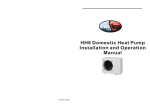
Air Purge
With respect to the preservation of terrestrial environment, adopt “Vacuum pump” for air purge
(Evacuate air in the connecting pipes) when installing the unit.
• Do not discharge the refrigerant gas to the atmosphere to preserve the terrestrial environment.
• Use a vacuum pump to discharge the air (nitrogen, etc.) remained in the set. If the air remains,
the capacity may decrease.
For the vacuum pump, be sure to use one with backflow preventer so that the oil in the pump
does not backflow into the pipe of the air conditioner when the pump stops.
(If oil in the vacuum pump is put in an air conditioner including R410A, it may cause trouble on the
refrigeration cycle.)
EN
Vacuum pump
As shown in the figure, connect the charge hose after the
manifold valve are closed completely.
(continued)
È
Disconnect the charge hose from the charge port.
È
È
Attach the connecting port of the charge hose with a
projection to push the valve core (setting pin) to the charge
port of the set.
È
Open handle Low fully.
È
Turn ON the vacuum pump (*1)
È
Loosen the flare nut of the packed valve (Gas side) a little to
check the air passes through. (*2)
È
Tighten the flare nut again.
Tighten valve and caps of the charge port surely.
*1 Use the vacuum pump, vacuum pump adapter,
and gauge manifold correctly referring to the
manuals supplied with each tool before using
them.
Check that the vacuum pump oil is filled up to
the specified line of the oil gauge.
*2 When air is not charged, check again whether
the connecting port of the discharge hose,
which has a projection to push the valve core, is
firmly connected to the charge port.
Compound pressure gauge
È
Execute vacuuming until the compound pressure gauge
indicates –101kPa (–76cmHg). (*1)
È
–101 kPa
(–76 cmHg)
Gauge manifold
valve
Handle Lo
Close handle Low completely.
Charge hose
(For R410A only)
È
È
Leave the vacuum pump as it is for 1 or 2 minutes, and check
the indicator of the compound pressure gauge does not
return.
Vacuum
pump
È
È
Handle Hi
(Keep fully
closed)
Charge hose
(For R410A only)
Vacuum pump
adapter for
counter-flow
prevention
(For R410A only)
Turn OFF the vacuum pump.
Open fully the valve stem or the valve handle. (First, at liquid
side, then gas side)
Pressure gauge
Charge port
(Valve core
(Setting pin))
Packed valve
at gas side
– 14 –
14-EN
Toshiba XXXXXXX(<SanSerif1>X/X)
+00EH99861901_01EN_Outdoor6HP_IM.book Page 15 Monday, June 2, 2008 6:00 PM
Outdoor Unit Installation Manual
Digital Inverter
Replenishing refrigerant
How to open the valve
Confirm the structure surely and then open or
close the valve.
▼ Liquid side
Open the valve with a 4-mm hexagon wrench.
▼ Gas side
This model is a 30 m chargeless type that does
not need to replenish refrigerant for refrigerant
pipes up to 30 m. When a refrigerant pipe longer
than 30 m is used, add the specified amount of
refrigerant.
Valve unit
Refrigerant replenishing procedure
Using a minus
screwdriver, turn it
counterclockwise by
90° until it hits the
stopper. (Full open)
1. After the vacuuming of the refrigerant pipe is
completed, close the valves and then charge
refrigerant while the air conditioner is not
working.
2. When the refrigerant cannot be charged to the
specified amount, charge the required amount
of refrigerant from the charge port of the valve
on the gas side during cooling.
Charge port
Requirement for replenishing
refrigerant
Flare nut
Replenish liquid refrigerant.
When gaseous refrigerant is replenished, the
refrigerant composition varies, which disables
normal operation.
Handle position
Closed completely
Opened fully
Stopper pin
Additional amount of refrigerant
31~50m: L
40g×(L-30)
Main stopper
Movable part of valve (Stem)
• While the valve is fully opened, after the
screwdriver has reached the stopper, do not
apply torque exceeding 5N•m. Applying
excessive torque may damage the valve.
Valve handling precautions
• Open the valve stem until it strikes the stopper.
It is unnecessary to apply further force.
• Securely tighten the cap with a torque wrench.
• Cap tightening torque
Valve size
Charge port
15-EN
Ø9.5 mm
33 to 42 N•m (3.3 to 4.2 kgf•m)
Ø15.9 mm
20 to 25 N•m (2.0 to 2.5 kgf•m)
• L: Pipe length
• For additional amount of refrigerant for twin
system and triple system, refer to the
installation manual supplied with the branching
pipe (sold separately).
• The refrigerant need not be reduced for a
30 meter (or less) refrigerant pipe.
14 to 18 N•m (1.4 to 1.8 kgf•m)
– 15 –
Toshiba XXXXXXX(<SanSerif1>X/X)
+00EH99861901_01EN_Outdoor6HP_IM.book Page 16 Monday, June 2, 2008 6:00 PM
Outdoor Unit Installation Manual
Digital Inverter
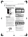
7
ELECTRICAL WORK
WARNING
1. Using the specified wires, ensure to connect
the wires, and fix wires securely so that the
external tension to the wires do not affect the
connecting part of the terminals.
Incomplete connection or fixation may cause a
fire, etc.
2. Be sure to connect earth wire. (grounding
work)
Incomplete grounding cause an electric shock.
Do not connect ground wires to gas pipes, water
pipes, lightning rods or ground wires for
telephone wires.
3. Appliance shall be installed in accordance
with national wiring regulations.
Capacity shortage of power circuit or incomplete
installation may cause an electric shock or a fire.
Furthermore, be sure to secure these wires with
the pipe valve fixing plate and cord clamps stored
in the electric parts box.
Electric parts box
Panel
Pipe valve
fixing plate
Cord
clamp
Pipe hole
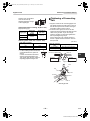
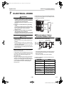
Wiring between Indoor
Unit and Outdoor Unit
CAUTION
• Wrong wiring may cause a burn-out to some
electrical parts.
• Be sure to use the cord clamps attached to the
product.
• Do not damage or scratch the conductive core
and inner insulator of power and inter-connecting
wires when peeling them.
• Use the power and Inter-connecting wires with
specified thickness, specified type and protective
devices required.
• Remove the panel, and you can see electric
parts on the front side.
• A metal pipe can be installed through the hole
for wiring. If the hole size does not fit the wiring
pipe to be used, drill the hole again to an
appropriate size.
• Be sure to clamp the power wires and indoor/
outdoor connecting wires with banding band
along the connecting pipe so that the wires do
not touch the compressor or discharge pipe.
(The compressor and the discharge pipe
become hot.)
The dashed lines show on-site wiring.
(Main circuit)
Input
power
220-240 V~,
50 Hz
EN
(Indoor/outdoor
connecting wires)
L
1
1
N
2
2
3
3
Outdoor unit
Earth
Leakage
breaker
Remote
controller
Indoor unit
Earth
• Connect the indoor/outdoor connecting wires to
the identical terminal numbers on the terminal
block of each unit.
Incorrect connection may cause a failure.
For the air conditioner, connect a power wire as
mentioned below.
Model RAVPower supply
Maximum running
current
Installation fuse rating
SM160
220-240 V~, 50 Hz
32 A
40 A
(all types can be used)
Power wire
H07 RN-F or 60245 IEC 66
(6.0 mm2 or more)
Indoor/outdoor
connecting wires
H07 RN-F or 60245 IEC 66
(1.5 mm2 or more)
Earth wire
H07 RN-F or 60245 IEC 66
(1.5 mm2 or more)
– 16 –
16-EN
Toshiba XXXXXXX(<SanSerif1>X/X)
+00EH99861901_01EN_Outdoor6HP_IM.book Page 17 Monday, June 2, 2008 6:00 PM
Outdoor Unit Installation Manual
Digital Inverter
How to wire
Wiring diagram
1. Connect the connecting wire to the terminal as
identified with their respective numbers on the
terminal block of indoor and outdoor unit.
H07 RN-F or 60245 IEC 66 (1.5 mm2 or more)
2. When connecting the connecting wire to the
outdoor unit terminal, prevent water coming in
the outdoor unit.
3. Insulate the unsheathed cords (conductors)
with electrical insulation tape. Process them so
that they do not touch any electrical or metal
parts.
4. For inter connecting wire, do not use a wire
jointed to another on the way.
Use wires long enough to cover the entire
length.
5. Wiring differs depending on single system,
twin system, and triple system to conform
to EMC standards. Connect wires according
to respective instructions.
* For details of wiring/installation of the remote
controller, refer to the Installation Manual
enclosed to in the remote controller.
▼ Single system
Remote controller
Remote controller
wiring
A
B
1
2
3
1
2
3
L
N
Indoor side
Indoor/Outdoor
connecting wires
Outdoor side
220-240V~
▼ Synchronous twin system
Remote controller
inter-unit wiring
Remote controller
CAUTION
Remote controller
wiring
• The installation fuse must be used for the power
supply line of this air conditioner.
• Incorrect/incomplete wiring might cause an
electrical fire or smoke.
• Prepare the exclusive power supply for the air
conditioner.
• This product can be connected to the mains.
Connection to the fixed wiring :
A switch which disconnects all poles and has a
contact separation of at least 3 mm must be
incorporated in the fixed wiring.
Indoor side
Indoor/Outdoor
connecting wires
A
B
1
2
3
1
2
3
L
N
Indoor
side
A
B
1
2
3
Indoor power
inter-unit wiring
Outdoor side
220-240V~
▼ Synchronous triple system
Remote controller
Remote controller
inter-unit wiring
Remote controller
wiring
Indoor side
A
Remote controller
inter-unit wiring
A
B
B
Indoor side
1
2
3
1
2
3
L
N
Indoor/Outdoor
connecting wires
Outdoor side
A
B
1
2
Indoor side
1
Indoor power
inter-unit wiring
2
3
3
Indoor power
inter-unit wiring
220-240V~
* Use 2-core shield wire (MVVS 0.5 to 2.0 mm² or more) for the remote controller wiring in the
synchronous twin and synchronous triple systems to prevent noise problems. Be sure to connect both
ends of the shield wire to the earth.
* Connect earth wire for each indoor unit in the synchronous twin and synchronous triple systems.
17-EN
– 17 –
Toshiba XXXXXXX(<SanSerif1>X/X)
+00EH99861901_01EN_Outdoor6HP_IM.book Page 18 Monday, June 2, 2008 6:00 PM
Outdoor Unit Installation Manual
Digital Inverter
▼ Single system
Power supply
terminal block
To Indoor unit
terminal block
1
2
3
1
2
3
Stripping length power cord and
connecting wire
L N
1 2 3
LN
10
10
L
N
50
60 40
30
Earth screw
Earth screw
Pipe valve fixing
plate
Connecting wire
10
10
(mm)
Earth line
Earth line
Power supply
wire
Connecting
wire
Power supply wire
▼ Twin system, Triple system
WARNING
For the synchronous twin and synchronous triple systems, perform the following to conform to EMC
standards.
1. Attach the supplied ferrite core (white) to indoor/outdoor connecting wires.
• Pass indoor/outdoor connecting wires A and B through the supplied ferrite core and wind them
making a single turn, and then connect them to the terminals of the outdoor unit. Connect the indoor/
outdoor connecting wire C and the earth wire directly to the outdoor unit terminals.
2. Attach the supplied clamp filter (gray) to the outdoor fan motor lead wire.
• Attach the supplied clamp filter securely to the fan motor lead wire (lower) in the electric parts box of
the outdoor unit.
EN
• For how to install the indoor unit, refer to the Installation Manual supplied with the indoor unit.
Stripping length power cord and
connecting wire
<1. Attaching the ferrite core>
To Indoor unit
terminal block
1
1
2
2
Power supply
terminal block
L N
3
1 2 3
3
L
N
160
Earth screw
Banding band
10
10
170
40
50
110
(mm)
Connecting
wire
Pipe valve fixing
plate
LN
10
10
Earth screw
Connecting wire
10
Earth line
Power supply
wire
Earth line
Power supply
wire
* Clamp the indoor/outdoor connecting wire C
and the earth wire together with the ferrite core
with the supplied banding band.
– 18 –
18-EN
Toshiba XXXXXXX(<SanSerif1>X/X)
+00EH99861901_01EN_Outdoor6HP_IM.book Page 19 Monday, June 2, 2008 6:00 PM
Outdoor Unit Installation Manual
Digital Inverter
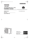
<2. Attaching the clamp filter>
CN301
CN300
Fan motor lead wire
(Lower side)
Banding band
Clamp filter
Attach the supplied clamp filter to the lower outdoor fan motor lead wire.
• Make sure that the claw of the clamp filter is securely locked.
• Pass the supplied banding band through the upper hole of the clamp filter to clamp it together with the
fan motor lead wire.
• The fan motor lead wires are connected to the connectors CN301 and CN300 on the P.C. board of the
outdoor unit.
19-EN
– 19 –
Toshiba XXXXXXX(<SanSerif1>X/X)
+00EH99861901_01EN_Outdoor6HP_IM.book Page 20 Monday, June 2, 2008 6:00 PM
Outdoor Unit Installation Manual
Digital Inverter
8
EARTHING
WARNING
• Be sure to connect earth wire. (grounding work)
Incomplete grounding cause an electric shock.
Connect the earth line properly following applicable technical standards.
Connecting an earth line is essential to prevent electric shock and to reduce noise and electricity charge
on the outdoor unit surface due to high frequency generated by the frequency converter (inverter) in the
outdoor unit.
If you touch the charged outdoor unit without earth line, you may feel electric shock.
9
FINISHING
After the refrigerant pipe, inter-unit wires, and drain pipe have been connected, cover them with finishing
tape and clamp them to the wall with off-the-shelf support brackets or equivalent.
Keep the power wires and indoor/outdoor connecting wires off the valve on the gas side or pipes that
have no heat insulator.
10 TEST RUN
EN
• Turn on the leakage breaker at least 12 hours before starting a test run to protect the
compressor during startup.
To protect the compressor, power is supplied from the 220-240 VAC input to the unit to preheat the
compressor.
• Check the following before starting a test run.
• All pipes are connected securely without leak.
• The valve is open.
If the compressor is operated with the valve closed, the outdoor unit is overpressurized, which may
damage the compressor or other components.
If there is a leak at a connecting part, air is sucked and the internal pressure further increases, which
may cause a burst or injury.
• Operate the air conditioner in the correct procedure specified in the Owner’s Manual.
11 ANNUAL MAINTENANCE
• For Air conditioning system which is operated regularly, cleaning and maintenance of the indoor/
outdoor units are strongly recommended.
As a general rule, if an indoor unit is operated for about 8 hours daily, the indoor/outdoor units will need
to be cleaned at least once every 3-month. This cleaning and maintenance shall be carried out by a
qualified person.
Failure to clean the indoor/outdoor units regularly will result in poor performance, icing, water leaking
and even compressor failure.
– 20 –
20-EN
Toshiba XXXXXXX(<SanSerif1>X/X)
+00EH99861901_01EN_Outdoor6HP_IM.book Page 21 Monday, June 2, 2008 6:00 PM
Outdoor Unit Installation Manual
Digital Inverter
12 FUNCTIONS TO BE IMPLEMENTED LOCALLY
Handling Existing Pipe
Recovering Refrigerant
When using the existing pipe, carefully check it for
the following:
• Wall thickness (within the specified range)
• Scratches and dents
• Water, oil, dirt, or dust in the pipe
• Flare looseness and leakage from welds
• Deterioration of copper pipe and heat insulator
• Use the refrigerant recovery switch SW802 on
the P.C. board of the outdoor unit to recover
refrigerant when the indoor unit or outdoor unit
is moved.
Cautions for using existing pipe
• Do not reuse the flare to prevent gas leak.
Replace it with the supplied flare nut and then
process it to a flare.
• Blow nitrogen gas or use an appropriate means
to keep the inside of the pipe clean. If discolored
oil or much residue is discharged, wash the pipe.
• Check welds, if any, on the pipe for gas leak.
Wall thickness (mm)
Ø9.5
0.8
Ø15.9
1.0
Ø19.0
1.0
Outdoor unit P.C. board
SW802
for
refrigerant
recovery
1 2 3 4 5 6
Reference outside
diameter (mm)
1. Turn on the power of the air conditioner.
2. Select the FAN mode for indoor unit operation
with the remote controller.
3. Press the refrigerant recovery switch SW802
on the P.C. board of the outdoor unit to drive
the air conditioner into the forced cooling mode
for up to 10 minutes. Open the valve to start
refrigerant recovery.
4. Upon completion of refrigerant recovery, close
the valve and press SW802 for at least one
second to stop operation.
5. Turn off the power.
ON
When the pipe corresponds to any of the
following, do not use it. Install a new pipe instead.
• The pipe has been open (disconnected from
indoor unit or outdoor unit) for a long period.
• The pipe has been connected to an outdoor unit
that does not use refrigerant R22, R410A or
R407C.
• The existing pipe must have a wall thickness
equal to or larger than the following thickness.
Procedure
SW801
for
existing
pipes
DANGER
• Never use any pipe with a wall thickness less
than these thicknesses due to insufficient
pressure capacity.
• To use an existing Ø19.0 mm pipe, set bit 5 of
SW801 (switch for existing pipe) on the P.C.
board of the outdoor unit to ON. In this case, the
heating performance may be reduced
depending on the outside air temperature and
room temperature.
Take care for an electric shock because the
P.C.board is electrified.
SW801 No.5
21-EN
ON
ON
1 2 3 4 5 6
1 2 3 4 5 6
– 21 –
Toshiba XXXXXXX(<SanSerif1>X/X)
+00EH99861901_01EN_Outdoor6HP_IM.book Page 22 Monday, June 2, 2008 6:00 PM
Outdoor Unit Installation Manual
Digital Inverter
13 TROUBLESHOOTING
You can perform fault diagnosis of the outdoor unit with the LEDs on the P.C. board of the outdoor unit
in addition to check codes displayed on the wired remote controller of the indoor unit.
Use the LEDs and check codes for various checks. Details of check codes displayed on the wired remote
controller of the indoor unit are described in the Installation Manual of the indoor unit.
LED indication and code checking
Cycle control P.C. board
LED indication
LED indication
Cause
D800 D801 D802 D803
D800 { : Red
D801 { : Yellow
D802 { : Yellow
D803 { : Yellow
: Rapid flash
● : Go off
{ : Go on
{
●
●
●
Heat exchanger sensor (TE) error
●
●
{
●
Suction sensor (TS) error
{
{
●
●
Discharge sensor (TD) error
●
{
●
{
Thermostat for compressor activated.
●
{
●
●
Outdoor temperature sensor (TO) error
{
{
{
●
DC outdoor fan error (Upper side)
{
{
{
{
DC outdoor fan error (Lower side)
{
●
●
{
Communication error between IPDU (Abnormal stop)
●
{
●
{
Comp. case thermo. operate – Serial signal error
●
{
{
●
Discharge temp. error
{
{
●
{
EEPROM error
●
●
{
{
Communication error between IPDU (No abnormal stop)
●
●
●
G – Tr short – circuit protection
●
●
Detect circuit error
●
●
Current sensor error
●
●
Comp. lock error
●
●
Comp. break down
●
●
EN
– 22 –
22-EN
Toshiba XXXXXXX(<SanSerif1>X/X)
+00EH99861901_01EN_Outdoor6HP_IM.book Page 23 Monday, June 2, 2008 6:00 PM
Outdoor Unit Installation Manual
Digital Inverter
14 APPENDIX
Instruction of Works:
The existing R22 and R407C piping can be reused for
our digital inverter R410A products installations.
NOTE
Confirmation of existence of scratch or dent of the
former pipes to be applied and also confirmation of
reliability of the pipe strength are conventionally
referred to the local site.
If the definite conditions can be cleared, it is
possible to update the existing R22 and R407C
pipes to those for R410A models.
Basic conditions need to reuse the existing pipe
Check and observe three conditions of the refrigerant
piping works.
1. Dry (There is no moisture inside of the pipes.)
2. Clean (There is no dust inside of the pipes.)
3. Tight (There is no refrigerant leak.)
Restricted items to use the existing pipes
In the following cases, the existing pipes cannot be
reused as they are. Clean the existing pipes or
exchange them with new pipes.
1. When a scratch or dent is heavy, be sure to use the
new pipes for the works.
2. When the thickness of the existing pipe is thinner
than the specified “Pipe diameter and thickness” be
sure to use the new pipes for the works.
• The operating pressure of R410A is high (1.6
times of R22 and R407C). If there is a scratch or
dent on the pipe or thinner pipe is used, the
pressure strength is poor and may cause
breakage of the pipe at the worst.
* Pipe diameter and thickness (mm)
Pipe outer diameter
Thickness
R410A
R22 (R407C)
Ø6.4
Ø9.5
0.8
0.8
Ø12.7 Ø15.9 Ø19.0
0.8
1.0
1.0
• In case that the pipe diameter is Ø12.7 mm or less
and the thickness is less than 0.7 mm, be sure to use
the new pipes for works.
3. The pipes are left as coming out or gas leaks.
(Poor refrigerant)
• There is possibility that rain water or air including
moisture enters in the pipe.
4. Refrigerant recovery is impossible.
(Refrigerant recovery by the air purge operation on
the existing air conditioner)
• There is possibility that a large quantity of poor oil
or moisture remains inside of the pipe.
5. A dryer on the market is attached to the existing
pipes.
• There is possibility that copper green rust
generated.
6. Check the oil when the existing air conditioner was
removed after refrigerant had been recovered.
In this case, if the oil is judged as clearly different
compared with normal oil
• The refrigerator oil is copper rust green :
There is possibility that moisture is mixed with the
oil and rust generates inside of the pipe.
• There is discolored oil, a large quantity of the
remains, or bad smell.
• A large quantity of sparkle remained wear-out
powder is observed in the refrigerator oil.
7. The air conditioner which compressor was
exchanged due to a faulty compressor.
When the discolored oil, a large quantity of the
remains, mixture of foreign matter, or a large
quantity of sparkle remained wear-out powder is
observed, the cause of trouble will occur.
8. Installation and removal of the air conditioner are
repeated with temporary installation by lease and etc.
9. In case that type of the refrigerator oil of the existing
air conditioner is other than the following oil (Mineral
oil), Suniso, Freol-S, MS (Synthetic oil), alkyl
benzene (HAB, Barrel-freeze), ester series, PVE
only of ether series.
• Winding-insulation of the compressor may
become inferior.
NOTE
The above descriptions are results of confirmation by
our company and they are views on our air
conditioners, but they do not guarantee the use of the
existing pipes of the air conditioner that adopted
R410A in other companies.
Branching pipe for simultaneous operation system
• In the concurrent twin system and triple system,
when TOSHIBA specified branching pipe is used, it
can be reused.
Branching pipe model name:
RBC-TWP30E2, RBC-TWP50E2, RBC-TRP100E
On the existing air conditioner for simultaneous
operation system (twin, triple system), there is a
case of using branch pipe that has insufficient
compressive strength.
In this case please change it to the branch pipe for
R410A.
Curing of pipes
When removing and opening the indoor unit or outdoor
unit for a long time, cure the pipes as follows:
• Otherwise rust may generate when moisture or
foreign matter due to dewing enters in the pipes.
• The rust cannot be removed by cleaning, and a new
piping work is necessary.
Place position
Outdoors
Indoors
23-EN
Term
Curing manner
1 month or more
Pinching
Less than 1 month
Every time
Pinching or taping
– 23 –
Toshiba XXXXXXX(<SanSerif1>X/X)
+00EH99861901_01EN_Outdoor6HP_IM.book Page 24 Monday, June 2, 2008 6:00 PM
Outdoor Unit Installation Manual
Digital Inverter
YES
Is there no scratch or dent on the existing pipes?
Existing pipes: Can not be used.
• Use a new pipes.
NO
NO
Is it possible to operate the existing air conditioner?
YES
• For cleaning the pipes and recovering of oil
• After the existing air conditioner operated in cooling mode
for approx. 30 minutes or longer*, recover the refrigerant.
• Refrigerant recovery: Pump down method
Nitrogen gas pressure 0.5 Mpa
• Remove the existing air conditioner from the piping and
carry out flashing (nitrogen pressure 0.5 Mpa) to remove
the remains inside of the pipe.
Note] In case of twin, also be sure to flash the
branching pipe.
(If there is discharge of remains,
it is judged that there is a large quantity of remains.)
Was not largely discolored oil or
a large quantity of remains discharged?
(When the oil deteriorates, the color of the
oil changes to muddy and black color.)
YES
Clean the pipes or use the new pipes.
EN
NO
Connect the indoor/outdoor units to the existing pipe.
• Use a flare nut attached to the main unit for the indoor/
outdoor units.
(Do not use the flare nut of the existing pipe.)
• Re-machine the flare machining size to size for R410A.
In case that the gas pipe Ø19 mm is used for the outdoor
unit of SP80 (3 HP) or bigger:
(Gas pipe size of our R410A model 3 to 6HP is Ø15.9 mm)
➞ Turn the existing pipe switch on the cycle control P.C
board of the outdoor unit to ON side.
At shipment from factory OFF ➞ ON for existing pipe
(Refer to the table below.) (Be sure to set the contents
in the table below in order to restrict the refrigerating
cycle pressure of the equipment in the pipe standard.)
Existing pipe SW
Switch
6 HP
Piping necessary to change the flare nut/
machining size due to pipe compression.
1) Flare nut width: H
H
(mm)
Copper pipe
outer dia.
Ø6.4
Ø9.5
Ø12.7
Ø15.9
For R410A
17
22
26
29
36
27
Same as
above
For R22
Same as above
24
Ø19.0
2) Flare machining size: A
Bit 5 of SW801 ➞ ON
(mm)
A
• (Airtight test), Vacuum dry, Refrigerant charge, Gas leak
check
Copper pipe
outer dia.
Ø6.4
Ø9.5
Ø12.7
Ø15.9
Ø19.0
For R410A
9.1
13.2
16.6
19.7
24.0
For R22
9.0
13.0
16.2
19.4
23.3
Becomes large a little for R410A
Do not apply the refrigerator oil to the flare surface.
Trial run
– 24 –
24-EN
Toshiba XXXXXXX(<SanSerif1>X/X)
+00EH99861901_10TR_H4_Out_IM 6HP.book Page 25 Wednesday, June 4, 2008 4:02 PM
EH99861901