1
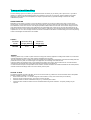
Issue 3 08~11 THURSTON BUILDING SYSTEMS Surestart User Manual Specification GENERAL DESCRIPTION Surestart anti-vandal low maintenance security buildings are designed and value engineered to provide long life durability, defeat unauthorised entry and combat vandalism in most hostile and remote environments. UNIT FLOOR Agrement certified moisture resistant heavy duty tongued and grooved flooring grade strand board fixed to galvanised joists at 300mm centres supported on welded steel angle perimeter base frame which is in turn supported on rolled steel channel skids extending the full length of the building. The floor is underdrawn with arson resistant galvanised sheet steel. The floor covering is a heavy-duty flexible sheet vinyl, with continuously welded joints and is bonded to floorboards. The floors are designed to provide for a uniform floor loading of 2.5kn/m2. The floor can be insulated as an optional extra. PLANT ROOM FLOOR 15mm WBP plywood with black oil resistant paint finish fixed to galvanised steel joists at 167mm centres incorporating 50x50x5mm SHS and supported on welded steel angle perimeter base frame which is in turn supported on rolled steel channel skids extending the full length of the building. The floor is underdrawn with arson resistant galvanised sheet steel. The floor is designed to provide for a uniform floor loading of 5kn/m2. The floor can be insulated as an optional extra. EXTERNAL WALLS The external walls are fully galvanised structural steel panels 305mm wide with integral supports. Wall sections are welded to the perimeter of both base frame and roof perimeter gutter. Internal finish is an embossed vinyl wall covering laminated to 12.5mm plasterboard lining and providing a class ‘O’ surface spread of flame with extruded plastic joint strips ‘unit only, plant room unlined’. Alternative linings are available on request. Wall cavities are insulated with 80mm non-combustible fibrous insulation and provides a ‘U’ value of 0.44w/mc ‘plant room uninsulated’. External finishes are spray applied semi-gloss fast enamel to BS 4800 with trims in a contrasting dark grey. Zinc rich galvanic primer is applied to all external mild steel surfaces and weld areas, all panel joints are polyurethane sealant sealed. Natural trickle ventilation is achieved by the incorporation of high and low level permavents. ROOF Heavy duty fully galvanised and mechanically interlocking structural steel panels are riveted, bonded and sealed with polyurethane adhesive. Rainwater is discharged at each corner via a perimeter galvanised steel guttering system to which optional extra rainwater pipes can be included if required. The internal ceiling finish is an embossed vinyl covering laminated to 12.5mm plasterboard lining providing class ‘O’ surface spread of flame fire rating as standard. The roof also incorporates fibrous insulation and provides a ‘U’ value of 0.44w/mc. Alternative linings are available. Plant room roof uninsulated and lined. WINDOWS Maintenance free aluminium framed polyester powder coated windows with top opening casements and casement stays glazed in 4mm float glass. Heavy duty horizontal sliding galvanised steel window shutters with internal single person operation are fitted as standard including locking bolts and other anti-jemmy features. SINGLE EXTERNAL DOORS External doors are constructed from galvanised steel, fully insulated. With a clear opening of 840x1940mm the single outward opening door is hung on a zinc plated full height ‘piano’ hinge welded to both door and steel frame and fitted with two five lever mortice deadlocks, a mortice latch, SAA lever furniture, and anti-jemmy security features. The door also incorporates fibrous insulation and provides a ‘U’ value of 0.697w/mc. DOUBLE PLANT ROOM DOORS External doors are constructed from galvanised steel. With a clear opening of 1994x2171mm the double outward opening doors are hung on a zinc plated full height ‘piano’ hinges welded to both door and steel frame and fitted with two five lever mortice deadlocks, and anti-jemmy security features. The doors also incorporate fixed vane louvered vents. INTERNAL DOORS Where indicated, 726mm wide doors factory pre assembled. Doors are fitted with chrome furniture and either a latch handle sliding door furniture, mortice lock or bathroom furniture. INTERNAL PARTITIONS Standard:Class ‘O’ vinyl faced 12.5mm plasterboard partition with extruded plastic joint strips and gyproc or similar approved steel channel studding and coved skirting to toilet area. Plant Room:Class ‘O’ vinyl faced 12.5mm plasterboard with extruded plastic joint strips facing the toilet accommodation onto 305mm galvanised steel wall panels painted to the plant room side. 1 Surestart Dimensions Table 1 Surestart dimensions in metres Surestart SSO2410 A B C D External Internal A B C D E F G H 7.47 3.41 3.01 3.31 4.27 1.524 3.16 2.70 Overall length including gutters Lifting Eye centre Lifting Eye centre Lifting Eye centre E F G H Length Width Height 7.14 2.84 2.42 External width of unit External length of unit. Height bottom of skid to top of roof Overall width including gutters. 2 Transport and Handling Thurston Building systems can deliver your preferred Surestart unit directly to your factory, site or point of use. If you wish to relocate your building Thurston Building systems can provide this service for you. However, Surestart buildings have been designed to make relocation and transportation as simple as possible and any reputable haulage contractor can readily undertake the process. CRANE HANDLING Depending on site access or location it may be necessary to position the unit using a mobile crane. Each unit has secure craning points; crane shackles/hooks must be of the correct rating. All craning points must be used to lift the unit to ensure an even distribution of load. The minimum chain lengths specified in table 2 below must be used. The maximum weight of the unit must not exceed the maximum lifting mass indicated on the specification plate, which can be found on the bottom skirt of the building. The minimum crane capacity will depend on the maximum mass of the unit to be lifted and the overall reach necessary to position the unit. Your local cranage contractor should be consulted and will advise on suitable lifting plant and route planning to ensure low bridges and obstructions are avoided. TABLE 2 Surestart Model Minimum Sling Length (Meters) Maximum Weight (Kg) SO2410 5.04 6000 TRANSIT Transit by platform lorry or trailer on public roads must comply with statutory legislation including Road Traffic Act, Construction and Use Regulations as well as any Local Authority regulations that may apply. The most important aspect to consider is the length and width of the building to be transported, and when the building skids are positioned on the lorry bed, the overall height, and if applicable, the overhang of the Surestart unit. Lashing locations are provided to each unit to enable secure lashing using chains. Ensure that there are no loose laid items within the unit and external doors and shutters fastened and locked, prior to departure. It is also essential that prior to transportation that all windows, shutters and doors are locked and bolted into the closed position, and that all fixtures and fittings within the unit are securely fixed in place. ACCESS TO SITE The following aspects will need to be taken into account to ensure that any problems on site are minimised and an acceptable standard of health and safety is maintained. Route and access to site – if in doubt arrange for a local haulier to survey route and access prior to delivery. Space on site for manoeuvring lorry, and crane if one is to be used. Potential hazards in relation to extended crane jib, e.g. overhead power cables. Combined mass of load and vehicle must be considered relative to ground conditions – temporary tracking may be required. 3 Siting and Foundations The Surestart units have been designed to withstand the extremes of the U.K. climate, and the strength and durability of our units has been proven by many years of experience in extreme environments. However, consideration of site conditions is necessary where locally they may be subject to chemical or exposed coastal sites. In such circumstances additional measures may be necessary and Thurston Building Systems will be pleased to advise. FOUNDATION DETAILS The standard Surestart unit must always be sited onto the metal base frame (skids) on any reasonable level site. Thurston Building Systems would be pleased to provide foundation loading recommendations upon request. The building should be positioned so that the weight of the building is evenly distributed to the ground. The building should be lowered as close to ground as possible, particularly on exposed sites. On sloping sites it is quite satisfactory for one end or one side of the unit to be supported on extending piers from the ground. In such circumstances it is important that the maximum pier height does not in any event exceed 750mm. N.B.: If the building is on an exposed or sloping site, bolting down of the unit is advisable. Metal shims may be required to ensure the unit is level and adequately supported. STACKING When stacking Surestart buildings it is essential that Surestart units on every occasion are skid mounted at ground level and only Thurston Building systems compatible units are utilised to stack over. This will however require the Surestart unit to be fitted with jacklegs as an optional extra fitting. It is important that the building foundations are capable of withstanding the full loads of all buildings, including all imposed snow loading and wind loads. This will generally involve the placement of concrete foundations, and competent professional advice should be sought to ensure that adequate provisions are made. FIG. 1 FIG. 2 FOUNDATION LOADS Foundation loads for Surestart buildings are based upon 5kn/m2 to the Plant room area and 2.5kn/m2 to the functional areas. Please request specific advice for three storey buildings from Thurston Building Systems, Fig. 2 above illustrates a typical 3storey foundation arrangement. THREE STOREY INSTALLATIONS The lower building must be adequately anchored to the foundations to prevent overturning and instability in high winds. Expansion bolts should be used to secure the leg base plate to the foundations. The inner legs must be retracted the pin secured through the outer leg. Under no circumstances should the legs be extended when multi stacking units. The jacklegs on the upper buildings must be retracted with pins passing through the third hole of the inner leg and the holes in the outer leg. Use only pins and bolts provided to bolt upper building to lower building via the leg base plate and top plates, with two bolts to each leg position. 4 Optional Variations Surestart buildings can be linked together on site to form various configurations or layouts to suit your particular needs. Linking of Surestart buildings is accomplished using a purpose made linkway. This provides a simple and reliable method of linking buildings together, and requires no special installation skills. The following linking arrangements can be achieved with the standard Sureguard building: Side to Side. End to End. Vertically (up to three storeys). Combinations of the above. Interlinking is also possible with different sized units throughout the range. OPTIONAL EXTRAS An extensive range of options is available to further enhance the tough and already well equipped Surestart unit, some of which are listed below: Anti-vandal steel or black plastic rainwater pipes. Insulated floors. Internal partitions and doors. Electric heating. Kitchen/Canteen and Changing room furniture and fittings. Additional Electrical and I.T. Fittings. External staircase and landings. External corporate colour schemes. A comprehensive range of plumbing fittings. Removable external door and frame. Jacklegs. Gas installations. REGULATIONS AND STATUTORY LEGISLATION When moving, linking or stacking units care should be taken that the layout formed by the linked buildings complies with relevant legislation – this will in general be the Building Regulations and the Fire Precautions Act. It should also be noted that any local health and safety arrangements including permit to work, induction procedures etc. should be taken into account. CONNECTION OF SERVICES Electrical Installation The electrical installation is designed and installed in accordance with the requirements of the IEE Regulations 17 th Edition 2008. Wiring is by twin and earth PVC insulated cables enclose in surface mounted PVC TRUNKING. The electrical trunking system are positioned at ceiling level around the internal perimeter of the building, and incorporate a detachable PVC capping piece to provide full access to wiring All circuits are wired to a multi-way consumer units positioned at high level, with terminals for direct connection to the site electrical supply. All circuits are provided with overload protection utilising miniature circuit breakers and RCD. The type of supply which may be either single or three phase depending on load requirements, and assessed maximum demand, are indicated on the certificate. The electrical installation is inspected and tested in accordance with IEE Regulations, and relevant certificate “Transportable Building Electrical Installation certificates” is supplied with the building, please ensure that the certificate is the correct one and is kept safely. On installation, any live testing should be carried out by an N.I.C.E.I.C contractor and all tests inserted on to electrical completion certificate once the building is live. This is recommended for every building relocation and re-connection. On Installation or relocation Item Details RCD (Main Switch) Check the incoming R.C.D (MAIN SWICH) is working correctly and that it is checked regularly. Maximum Frequency At each relocation Water Heaters Check that all water heaters have the water turned on before switching on the isolators. At each relocation Lighting Room Heaters Carry out functional checks on all lights, and ensure all lamps are in the correct position Check all room heaters have all the packaging removed . Sockets Check all sockets are working correctly Thermostats Check all thermostats that control heaters are working correctly PIR’s & control Check operation of PIR’s At each relocation At each relocation At each relocation At each relocation At each 5 features relocation Natural Gas and LPG Installations Natural Gas installations, where installed, are carried out in accordance with the GAS SAFETY (installation and use) REGULATIONS 1984 and recommendations DM2 Code of Practice for Gas Installations. Completed installations are tested in accordance with all relevant recommendations, and a gas soundness test certificate is supplied with the building. LPG installations are designed, installed and tested in accordance with BS 5482 Pt 2 1988, and a relevant gas soundness test certificate is supplied with the building. Ventilation air for combustion is provided by fixed wall ventilators positioned at high and low level in accordance with BS 5482 Pt 1. At no time should any of the ventilators be covered or obscured. Health and Safety information for the use of LPG Installations is supplied with the building. When the building is in use, this information should be prominently displayed to users and occupants alike. No additional gas fittings should be incorporated without first checking that adequate ventilation is available. Water Hot and cold water distribution, where installed is in accordance with the recommendations of BS 6700: 1987. Completed installations are pressure tested prior to despatch details of test are supplied with each building. Drainage Soil and waste systems are installed in polypropylene and PVCu pipework, in accordance with BS 5572. Telephones Attention is drawn to the Telecommunications Act 1984 which requires apparatus to be approved before it can be connected to networks run by British Telecom. Any alteration to or servicing of, the units must be carried out by a suitably qualified operative. Inspection and Maintenance Surestart buildings have been developed to provide tough and durable accommodation for a great variety of uses, requiring little maintenance throughout their useful life. However, where a high level of aesthetic appearance is paramount or where in use conditions are particularly severe, positive action can be taken in the form of regular maintenance and inspection, to retain the Surestart building in prime condition. INSTALLATION CERTIFICATES All installation certificates and instructions for equipment fitted to the services will be itemised on a Warranty Notice – checklist, delivered with the unit. To ensure that the terms of the Warranty are effective, the notice should be returned once all the documents have been received. FIXINGS TO WALLS AND INTERNAL PARTITIONS Lightweight Items Lightweight items such as notice boards, etc., can be fastened directly to internal walls and partitions, with proprietary gypsum board fixings with self-drilling action. Heavyweight Items Heavyweight items such as shelving, wall-mounted cupboards, etc., should be fixed to walls and partitions with expanding steel cavity fasteners. Care should be taken to follow the manufacturers instructions, particularly with respect to pilot hole size and resist over-tightening the fixing screws. Exceptionally heavy items such as storage water heaters, etc., should ideally be positioned so that the weight is transferred directly to the floor. This can be achieved by first fixing a full height plywood or similar backboard to the wall, with the base of the board supported by the floor. UNIT INSPECTION AND MAINTENANCE SCHEDULE Item Welds Details Check welds, where appropriate, in the following locations for corrosion. If required clean and prepare the affected area, apply a painted galvanising primary coat and finishing coats as paint manufacturers instructions: 1 Light duty lifting eye jackleg brackets 2 Roof steelwork for lifting eyes. 3 Base lifting brackets. 4 Wall panel/roof connections. 5 Wall panel/base connections. 6 All base frame welded joints. 7 Roping down brackets. 8 Base mounted lifting brackets. 9 Roof anchors 10 Low level jackleg mounted lifting bracket Maximum Frequency Annually 6 Gutters Check for debris and leaves or damage to gutter, which may cause gutters to overflow and cause pattern staining to external walls. Annually Roofs Inspect for evidence of deterioration of: 1. roof panel to panel seals, 2. security and condition of adhesive gaskets at the ends of each roof panel seal 3. Particularly in exposed or costal/ industrial environments, but generally anyway assess galvanising of roof panels for breakdown, maintain or paint as appropriate 4. Ensure that insulation is in place and that it is not waterlogged. Check that any electrical heating installed for frost protection is in working order. Annually Frost protection Annually & As IEE requirements Plumbing General Ensure all plumbing is isolated from mains before disconnection, Components selected are supported by any plumber’s merchant in terms of spares & seal kits. Check for operation, flow, leakage, security and any damage to ‘porcelain’ equipment, check also security of W/C seats (safety) Annually Overflows Check that overflows are not blocked and that any discharge can be readily observed. Six months Window seals Ensure that the rubberised window seal have not become dislodged or damaged, replace if necessary. Any surface damage to the powder coating of the window frame to be cleaned and apply touch-up paint to the area of damage. Six months Floor vinyl Ensure that any tears or damage to the floor vinyl and coved skirtings if specified are repaired, particularly in wet areas. Six months External Finishes The external finish should be checked for scratches and marks and the appropriate touch up paint applied in accordance with manufacturer’s instructions. The external finish can be cleaned using propriety cleaners such as domestic detergent diluted with clean water. Six months Electrical Installations The electrical installation should be periodically inspected and tested in accordance with the IEE regulations. Convector Heaters Convector heaters should not be used for drying purposes, covered with garments, etc., due to the possible fire risk. Floor loadings The maximum floor loading capacity should not be exceeded. Door Hinges Roofs Lightly oil to ensure trouble-free operation. Check roof joint seals Annually Sliding Shutters Ensure shutter cord is not damaged and that the bearings run freely, if required replace cord and lubricate bearings Annually As IEE requirements Electrical Specifics Item Details Maximum Frequency At each relocation or annually RCD (Main Switch) Check the incoming R.C.D (MAIN SWICH) is working correctly and that it is checked regularly. Frost Protection Ensure that insulation is in place and that it is not waterlogged. Check that any electrical heating installed for frost protection is in good working order, Especially before winter frost and cold weather. NOTE Frost stats are installed to turn heaters on when the temperature drops to near freezing and will not generally operate in the summer months. Frost protection heaters will only stop pipes from freezing, and are not for general space heating Annually Convector heaters The electrical installation should be periodically inspected and tested in accordance with the IEE regulations. Convector heaters should not be used for drying purposes, covered with garments, etc ., due to the possible fire risk. Desks should not be pushed over the tops of the convector heaters. As IEE Regulations Drying Rooms Tubular Heaters may be installed within Drying Rooms and are controlled via a room stat. These heaters are installed under benches and coat rails, providing a constant heat for keeping the temperature high for drying clothing. This heating will generally be supplemented by a larger high level fan heater. The fan heaters are used to boost the heating when clothing is wet. Once a high temperature is reached the tubular heaters will keep the room warm. Annually High level Fan Heaters These heaters are either AC3 (3KW) OR 2 Dimplex FX 20 type heaters (2kw or 1 kw). Or equivalent. Under no circumstance should clothing be hung over these fan heaters. Besides being a major fire risk, this practise will void the warranty and cause the heaters to overload and burn out Annually 7 Water Heating Water heating is generally over sink or a under sink type. Each heater should have a 3 bar reducing valve fitted. See specification sheets. These water heaters have resettable thermal overloads, should an overload trip, thepower can be turned off and back on. This will reset the overload. The overload will operate should the heaters be powered up with the water vessels empty. Heaters would not be starved of water. Should the water supply be disrupted, the power supply should be switched off. When the water is restored the water heaters need filling then the electric supply can be switched back on . Annually PIR, & cabin controls Subject to specification, a cabin may have additional controls, typically for eco features. Check functionality , do not attempt to service or tamper. Annually All Electrical Appliances Before faulty equipment is reported under warranty. Please check that the local Isolation to the equipment. This a switched fused spur and occasionally This fuses within the spur unit blow or are removed by people on site to fit into 13 amp plug tops. Before reporting a problem Plant Service, Commissioning and Decommissioning checklist COMMISSIONING Prior to the utilisation of a Surestart unit the following procedure should be carried out to prevent plant or equipment failure. Ensure all isolation valves are open ‘to the on position’. In particular w.c. cistern, urinal cistern and electrical water heaters. Ensure that the water pump is suitably primed; refer to the manufacturer’s instructions supplied with the unit. Never activate electrical water heaters until water has been fully drawn through the system since this would damage heaters beyond repair and result in significant cost to replace. Ensure all generator operation switches are activated prior to ignition start; please refer to generator manual provided. Ensure that the macerator tank and pipework are clean and operable. IN SERVICE During the utilisation of the Surestart unit the plant room area and equipment should be regularly monitored to prevent plant or equipment failure and the following fundamental checks should be carried out on a daily basis. Ensure that the water storage tank is sufficiently full for its daily usage. Ensure that the fuel storage tank ‘occasionally integral to the generator’ is sufficiently full for its daily usage. Ensure that the effluent tank has sufficient capacity to allow its daily usage. Ensure all louvers are free from obstruction. Ensure that the generator manufacturers literature supplied with the unit, in particular maintenance and servicing recommendations are undertaken. Ensure that all vents (including vent to water tank), fans (where supplied), and fixed vane louvered apertures are free of obstructions and operational. Ensure that diesel, effluent and water tanks are checked on a daily basis for leaks and spillage’s, to safeguard against cross contamination. Ensure that the resilient mountings to the generator are not worn or perished. Please note that water heaters will not operate unless a water supply is available. Please note that the cold water supply is automatically terminated by a float switch in the effluent tank at maximum capacity, this will also terminate power to the instantaneous water heaters as noted in the previous comment. DECOMMISSIONING Prior to the relocation or storage of a Surestart unit the following procedure should be carried out to prevent plant or equipment failure. Drain off and empty all water tanks and pipe work. Ensure all are closed ‘in the off position’ In particular w.c. cistern, urinal cistern and electrical water heaters. Ensure that the water pump is suitably drained; refer to manufacturers instructions supplied with the unit. Ensure that the effluent tank is drained and empty. Ensure that the fuel tank ‘occasionally integral to the generator’ is drained and empty. Ensure that the macerator tank and pipework are thoroughly cleaned. Please note: Where a generator is replaced or renewed that any replacement should be fit for purpose and suitable for operation within the plant room provided, please contact Thurston Building Systems for any further advice. All commissioning, decommissioning and in service maintenance must be carried out by a suitably qualified individual. 8 HEALTH & SAFETY The responsibility for safe working with or on any Surestart unit rests with the owner, or related contractor(s). Material safety data sheets relating to materials used within the building construction are available on request. In addition to advice given in the main text, your attention is drawn to the requirements of the Health & Safety at Work etc. Act, and in particular the following Regulations and Standards: The Management of Health & Safety at Work Regulations (including the requirement of Risk Assessments for work or activities to be completed). Lifting Operations and Lifting Equipment Regulations BS7121 Mobile Cranes. Electricity at Work Regulations (and IEE Requirements) Control of Substances Hazardous to Health Regulations Construction (Health, Safety and Welfare) Regulations Construction (Design and Management) Regulations BS6492: Part 2 Transportable Accommodation Units. (Transportation and Siting). The list above is not intended as a definitive list, but a listing of the main documentation that may relate to users of Sureguard buildings. Further advice on these publications can be obtained from: Health and Safety Executive and British Standards: Every effort has been made to ensure the accuracy of the contents of this guide. It is however intended for guidance only and Thurston Building Systems can accept no responsibility whatsoever for any outcome of the use of advice herein. In accordance with Thurston Building Systems policy of continuous product development and improvement, we reserve the right to make design and specification changes without prior notice. 9