1
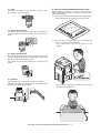
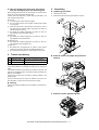
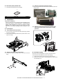
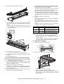
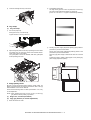
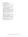
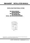
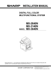
TopPage
INSTALLATION MANUAL
DIGITAL MULTIFUNCTIONAL SYSTEM
MX-M365/M364 N
MX-M465/M464 N
MODEL MX-M565/M564 N
Parts marked with " " are important for maintaining the safety of the set. Be sure to replace these parts with
specified ones for maintaining the safety and performance of the set.
SHARP CORPORATION
This document has been published to be used
for after sales service only.
The contents are subject to change without notice.
MX-M565N
[1] MX-M365N/M465N/M565N
MX-M364N/M464N/M564N
(3)
Power frequency, waveform
6HUYLFH0DQXDO
The frequency must be within the range of the specified frequency
+/-2%. If power waveform is deformed, a trouble may occur.
(4)
1. Installing (use) conditions
Safety
Be sure to properly ground the machine.
Before installing the machine, check that the following installing
(use) conditions are satisfied.
Grounding (earth connection) must be performed before inserting
the power plug into the power outlet.
If the installing (use) conditions are not satisfied, the machine may
not achieve full performances, resulting in troubles. It may also
cause safety problems. Therefore, be sure to provide the installing
(use) conditions before setting up the machine.
When disconnecting the earth connection, be sure to disconnect
the power plug from the power outlet in advance.
No.
1
2
3
4
5
Content
Bringing space
Installing space
Power source (Capacity, fluctuation, safety)
Floor strength
Direct rays of the sun, dust, temperature, humidity, gases,
chemicals
A. Bringing space
For installation of a large size machine, be sure to check that the
door size is wide enough before bringing in.
(5)
Power plug
Check the shape of the power plug of the machine, and insert it into
a power outlet of the acceptable shape.
D. Floor strength and level
This machine is considerably heavy and becomes heavier with an
option installed.
The floor must be strong enough for assuring safety.
If the unit is not horizontally installed, the toner density control is not
performed normally, degrading the copy quality.
If not, color shift or image distortion may occur.
B. Installing space
The following space must be provided around the machine in order
to assure machine performances and proper operations.
If any option is installed, provide the additional space for installing
it.
Adequate space must be provide behind the machine for proper
ventilation heat and dust. If not, the machine cannot exhibit functions against heat and dust, causing some troubles.
E. Direct rays of the sun, dust, temperature,
humidity, gases, chemicals, vibration
11-13/16"
(30cm)
(1)
11-13/16"
(30cm)
17-23/32"
(45cm)
Temperature and humidity
This machine is designed to perform properly under the specified
temperature and humidity. If the temperature and humidity exceeds
the specified range, the machine may not operate properly and or
cause equipment failure.
Especially when the humidity is too high, paper absorbs humidity to
cause a paper jam or dirty copy.
Do not install the machine near a heater, a cooler, or a humidifier.
C. Power source (Capacity, voltage, frequency,
safety, plug)
If the power specifications are not satisfied, the machine cannot
exhibit full performances and may cause safety trouble.
Strictly observe the following specifications.
(1) Power capacity
Check that the following power capacity is satisfied. If not, additionally provide a power source.
Dew may be formed inside the machine to cause a trouble. Use
enough care for ventilation.
Current capacity
Humidity㧔RH㧕
Japan: 20A or more
100V: 15A or more
85%
200V: 10A or more
60%
NOTE: Check the shape of the power plug of the machine, and
insert it into a power outlet of the acceptable shape.
(2) Power voltage
Measure the voltage during copying to check that the voltage is in
the range of the specified voltage +/-10%.
20%
If the voltage is outside the specified range, call a qualified electrician and have the proper voltage/amps/hertz supplied to the copier.
- Working environment
(An electrical work is required.)
Call a qualified electrician and have the proper voltage/amps/hertz
supplied to the copier. In this case, the capacity must be great
enough for the max. power consumption of the machine.
Temperature: 10 to 35 degrees C
Humidity: 20 to 85% RH
Atmospheric pressure: 590 to 1013hPa (altitude: 0 to 2000 m)
MX-M565N MX-M365N/M465N/M565N MX-M364N/M464N/M564N 1 – 1
(2) Dust
F. Note for handling PWB and electronic parts
If dust enters the machine, it may cause dirty copy and a paper
jam, resulting in a shortened lifetime.
When handling the PWB and the electronic parts, be sure to
observe the following precautions in order to prevent against damage by static electricity.
1)
When in transit or storing, put the parts in an anti-static bag or
an anti-static case and do not touch them with bare hands.
2)
When and after removing the parts from an anti-static bag
(case), use an earth band as shown below:
(3) Direct rays of the sun
If the machine is installed under the rays of the sun, the exterior of
the machine may be discolored and abnormal copies may be produced.
-
Put an earth band to your arm, and connect it to the
machine.
(4) Gases and chemicals
Do not install the machine at a place where there are gases and
chemicals. Especially be careful to avoid installation near a diazotype copier, which produces ammonium gas.
Copy quality may be adversely affected and a trouble may be
caused.
(5) Vibration
Avoid installation near a machine which produces vibrations.
If vibrations are applied to the copier machine, copy images may be
deflected and a trouble may be caused.
- When repairing or replacing an electronic part, perform the
procedure on an anti-static mat.
MX-M565N MX-M365N/M465N/M565N MX-M364N/M464N/M564N 1 – 2
G. Note for handling the drum unit, the transfer
unit, the developing unit, and the fusing unit
When handling the OPC drum unit, the transfer unit, and the developing unit, strictly observe the following items.
If these items are neglected, a trouble may be generated in the
copy and print image quality.
3. Unpacking
A. Unpacking procedure
1)
Remove the PP band.
2)
Remove the internal packing pads with the machine.
(Drum unit)
1)
Avoid working at a place with strong lights.
2)
Do not expose the OPC drum to lights including interior lights
for a long time.
3)
When the OPC drum is removed from the machine, cover it
with light blocking material. (When using paper, use about 10
sheets of paper to cover it.)
4)
Be careful not to attach fingerprints, oil, grease, or other foreign material on the OPC drum surface.
(Transfer unit)
1)
Be careful not to attach fingerprints, oil, grease, or other foreign material on the transfer roller.
(Developing unit)
1)
Be careful not to attach fingerprints, oil, grease, or other foreign material on the developing unit.
(Fusing unit)
1)
Be careful not to put fingerprints, oil, grease, or other foreign
material on the fusing roller and the external heating belt.
2)
Do not leave the fusing roller in contact state for a long time.
2. Transit and delivery
No.
1
2
Content
Implements, facility,
and man power
Delivery
Method
Use a forklift. (If no forklift is available,
manpower of two persons is required.)
Transit must be made in packed condition.
B. Removal of the fixing tape and protection
material
A. Implements, facility, and manpower
It is recommendable to use a forklift for bringing in the machine for
safety.
If no forklift is available, man-power of two persons is required. The
machine is considerably heavy, and requires safety precautions for
delivery and installation.
Transit of the machine must be made in packed condition to the
installing place.
Since the hard disk drive is built in the machine, use care not to
exert vibrations or shocks to the machine when in transit.
B. Delivery
Remove the packing materials prior to installation in the office environment.
C. Removal of parts packed together
MX-M565N MX-M365N/M465N/M565N MX-M364N/M464N/M564N 1 – 3
D. Check the parts packed item
(3)
1)
1) Open the right door and pull out the drum protection sheet from
transfer roller.
Check that all the parts are in the package.
Removal of the drum protection sheet.
1
NO.
1
Parts name
Operation manual
Quantity
1
4. Installation
<Note before installation>
* When connecting the main unit with the optional STAND/1 X 500/
2X500/3X500 SHEET PAPER DRAWER or STAND/500&2000
SHEET PAPER DRAWER, first unpack and install the PAPER
DRAWER; then unpack the main unit and securely place the
main unit on the PAPER DRAWER before installing the main
unit.
(4)
A. Lock release
Removal of the fusing heat roller protector and
push down the pressure release lever to apply
pressure
(1) Tray rotation plate lock release
1)
Pull out the tray, and remove the rotation plate fixing material
and the tray note label.
2)
Attach the removed fixing material to the position shown in the
figure for storage.
(2) Scanner (2/3 mirror unit) lock release
1)
Remove the optical unit fixing screw, and remove the note
label.
B. Developer supply
Be careful not to put fingerprints or oil dirt on the roller surface.
Do not hold the case adjacent to the DV roller strongly.
2
1)
Open the front cabinet, and remove the waste toner box.
2)
Remove the fixing screw of the developing unit, and pull out
the developing unit.
3
1
MX-M565N MX-M365N/M465N/M565N MX-M364N/M464N/M564N 1 – 4
3)
Remove two screws. Remove the DV cover.
5)
When [EXECUTE] key is pressed, it is highlighted. The developing roller rotates, and the toner density sensor detects toner
density, and the output value is displayed.
The above operation is executed for 2 minutes, and the average value of the toner density sensor detection level is set
(saved) as the reference toner density control value.
When the reference toner density control adjustment operation
is completed, [EXECUTE] key returns to normal from highlight.
This indicates whether the adjustment operation is completed
or not.
6)
Press the CA key to exit the simulation.
NOTE:
If the operation is interrupted within 2 minutes, the adjustment
result is not reflected.
4)
When [EXECUTE] key is pressed during rotation, the operation is stopped and [EXECUTE] key returns to the normal display.
While supplying developer from the developer supply port of
the developing unit, turn the MC gear counterclockwise by
using UKOG-0341FCZZ to supply all developer to the developing unit.
* Before opening the developer bag, shake the bag to mix
toner and developer in the bag, and then supply developer
to the developing unit.
If [EE-EU] or [EE-EL] is displayed, setting of the reference
toner density control value is not completed normally.
Error display
EE-EL
Content
EL abnormality
EE-EU
EU abnormality
EE-EC
EU abnormality
Details of content
Sensor output level less than 77, or
sensor control voltage level over 207
Sensor output level over 177, or sensor
control voltage level less than 52
Sensor output level less than 128, or
sensor control voltage level over 131
NOTE: When not replacing the developer, don’t execute SIM25-2.
Only execute SIM 25-2 when replacing the Developer.
SIM 25-2 should only be run immediately after installing
new DV material.
Toner Concentration Reference Control Level Setting will
be incorrect if SIM 25-2 is performed at any other time.
D. Install toner cartridge
5)
Attach the DV cover to the machine.
* Check to confirm that the pawl is securely engaged.
6)
Insert the developing unit into the machine, and fix it with the
blue screw.
7)
Install the waste toner box.
1)
Shake the toner cartridge several times.
2)
Open the front cabinet, and insert the toner cartridge.
C. Toner density reference control level setting
NOTE: Execute Toner density reference control level setting
without installing the toner cartridge.
1)
2)
Insert the power plug into a power outlet. With the front cabinet
open, turn ON the power switch of the machine and the power
switch on the operation panel.
With the front cabinet open, enter SIM 25-2.
WARNING: Do not install the toner cartridge before completing the Toner density reference control level setting (SIM 25-2).
3)
Close the front cabinet.
4)
After completion of the adjustment of the toner density control
reference value, insert the toner cartridge.
* Do not forcibly insert the toner cartridge.
Keep holding the cartridge and completely insert it.
* When the machine is transported with the developing unit
removed, be sure to remove the toner cartridge. (If not, toner
may be clogged.)
MX-M565N MX-M365N/M465N/M565N MX-M364N/M464N/M564N 1 – 5
3)
2)
Insert the cartridge securely until it locks.
Press [EXECUTE] button.
The high density process control is performed, and the copy
gray patch image (adjustment pattern) is printed out.
(A4/11" x 8.5" or A3/11" x 17" paper is automatically selected.)
E. Tray setup
(1) Tray size setup
1)
Pull out the paper tray.
Gently pull the tray out until it stops.
If paper remains in the tray, remove it.
3)
2)
Adjust the guide plates A and B by squeezing their lock levels
and sliding them to match the vertical and horizontal dimensions of the proper to be loaded.
The guide plates A and B are slidable, slide each guide plate
while squeezing lock lever.
Set the gray patch image (adjustment pattern) paper printed in
procedure 2) on the document table.
Set the gray patch image (adjustment pattern) printed in the
procedure 2) on the document table.
Place the gray patch image so that the fine lines are on the left
side.
At that time, place 5 sheets of white paper on the printed gray
patch image (adjustment pattern).
A
B
F. Image quality check
Be sure to check the following items related to image quality. For
details of the adjustment and checking procedures, refer to the “[5]
ADJUSTMENT” on the Service Manual.
Check that the following items are within specification. If not, carry
out the adjustment.
NOTE: When installing the copier, be sure to carry out the copy
gray balance and the printer gray balance.
(1) Image loss, void area (see ADJ 9)
(2) Copy gray balance (11-A / Auto adjustment)
1)
Enter the SIM 46-74 mode.
MX-M565N MX-M365N/M465N/M565N MX-M364N/M464N/M564N 1 – 6
4)
Press [EXECUTE] button.
6)
The copy density and gradation adjustment is performed automatically, and the adjustment pattern is printed.
Set the gray patch image (adjustment pattern) printed in the
procedure 5) on the document table.
Set the gray patch image (adjustment pattern) printed in the
procedure 2) on the document table.
If there is any streak or unclear print on the printed check pattern, check the print engine for any problems.
Place the gray patch image so that the fine lines are on the left
side.
At that time, place 5 sheets of white paper on the printed gray
patch image (adjustment pattern).
.QYFGPUKV[
*KIJFGPUKV[
# $ % & ' ( ) * + , - . / 0 1 2 3
Უ6JGOCZFGPUKV[UGEVKQPKUPQVDNWTTGF
Უ2CVEJ%QT&KUXGT[UNKIJN[EQRKGF
Უȷ6JGRCVEJFGPUKV[KUKFGPVKECNDGVYGGPRCVEJGUQTPQVTGXGTUGF
ȷ6JGRCVEJFGPUKV[KUEJCPIGFITCFWCNN[
5)
Press [EXECUTE] key.
The printer gray patch image (adjustment pattern) is printed
out.
(A4/11" x 8.5" or A3/11" x 17" paper is automatically selected.)
7)
Press [EXECUTE] key.
The printer gray balance adjustment (step 1) is automatically
performed and the gray balance check patch image is printed
out.
If there is any streak or unclear print on the printed check pattern, check the print engine for any problems.
.QYFGPUKV[
*KIJFGPUKV[
# $ % & ' ( ) * + , - . / 0 1 2 3
Უ6JGOCZFGPUKV[UGEVKQPKUPQVDNWTTGF
Უ2CVEJ#QT$KUXGT[UNKIJN[EQRKGF
Უȷ6JGRCVEJFGPUKV[KUKFGPVKECNDGVYGGPRCVEJGUQTPQVTGXGTUGF
ȷ6JGRCVEJFGPUKV[KUEJCPIGFITCFWCNN[
8)
The initial setting menu of the halftone image correction is displayed.
Press [OK] key.
The initial setting of the halftone image correction is performed.
MX-M565N MX-M365N/M465N/M565N MX-M364N/M464N/M564N 1 – 7
9)
Wait until [EXECUTE] key is displayed.
When it is displayed, press it.
The halftone image correction is performed.
10) When "COMPLETED THIS PROCEDURE" is displayed, the
adjustment operation is completed.
Cancel SIM46-74.
NOTE: The adjustment result becomes valid only when the both
adjustments in the copy mode and in the printer mode are
completed.
For example, if the copy gray balance adjustment (automatic adjustment) is performed and the simulation is canceled, the adjustment result is invalid.
11) Check the copy gray balance and density.
(Refer to the item of the copy gray balance and density check.)
When the gray balance and the density are unsatisfactory after
the automatic adjustment by selecting the factory target in procedure 4), execute the manual gray balance adjustment
(ADJ11C (2)).
Also when the service target is selected in procedure 4) to execute the automatic adjustment and a satisfactory result is not
obtained, perform the manual gray balance adjustment (ADJ
11C (2)).
12) Check the printer gray balance and density.
(Refer to the item of the printer gray balance and density
check.)
If a satisfactory result on the gray balance and the density is
not obtained with the automatic adjustment, execute the manual adjustment (SIM 67-25) (ADJ 11E (2)).
Also when the service target is selected in procedure 7) to execute the automatic adjustment and a satisfactory result is not
obtained, perform the manual gray balance adjustment (ADJ
11E (2)).
If the gray balance or density is not in the satisfactory level
even after execution of the automatic and manual adjustments,
there may be another cause.
Troubleshoot the cause, repair or perform necessary works,
and repeat the adjustment from the beginning.
MX-M565N MX-M365N/M465N/M565N MX-M364N/M464N/M564N 1 – 8