1
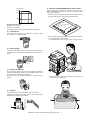
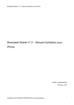
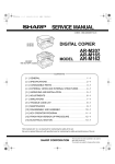
INSTALLATION MANUAL
DIGITAL MULTIFUNCTIONAL SYSTEM
MX-M264U/M264N/
M264NV/M264NR
MX-M314U/M314N/
M314NV/M314NR
MODEL MX-M354U/M354N/354NR
Parts marked with " " are important for maintaining the safety of the set. Be sure to replace these parts with
specified ones for maintaining the safety and performance of the set.
SHARP CORPORATION
This document has been published to be used
for after sales service only.
The contents are subject to change without notice.
MX-M264U
Transit, Installation (using) environment,5GTXKEG/CPWCN
Note
* About a main unit illustration, it may differ from a target model.
1. Installing (use) conditions
(3)
Before installing the machine, check that the following installing
(use) conditions are satisfied.
If the installing (use) conditions are not satisfied, the machine may
not display full performances, resulting in troubles. It may also
cause safety problems. Therefore, be sure to arrange the installing
(use) conditions before setting up the machine.
No.
1
2
3
4
5
Content
Transportation space
Installing space
Power source (Capacity, fluctuation, safety)
Floor strength
Direct rays of the sun, dust, temperature, humidity, gases,
chemicals
Power frequency, waveform
The frequency must be within the range of the specified frequency
r2%. If power waveform is deformed, a trouble may occur.
(4)
Safety
Be sure to properly ground the machine.
Grounding (earth connection) must be performed before inserting
the power plug into the power outlet.
When disconnecting the earth connection, be sure to disconnect
the power plug from the power outlet in advance.
(5)
Power plug
Check the shape of the power plug of the machine, and insert it into
a power outlet of the acceptable shape.
Power plug stated in power capacity.
D. Floor strength and level
A. Transportation space
For installation of a large size machine, be sure to check that the
door size is wide enough before bringing in.
This machine is considerably heavy and becomes heavier with an
option installed.
B. Installing space
The floor must be strong enough to safely support the weight of the
machine as well as any installed options.
The following space must be provided around the machine in order
to assure machine performances and proper operations.
If the unit is not horizontally installed, the toner density control is not
performed normally, degrading the copy quality.
If any option is installed, provide the additional space for installing
it.
If not, color shift or image distortion may occur.
To assure proper Image quality, make sure the machine is setting
level.
Adequate space must be provide behind the machine for proper
ventilation heat and dust. If not, the machine cannot exhibit functions against heat and dust, causing some troubles.
11-13/16"
(30cm)
11-13/16"
(30cm)
17-23/32"
(45cm)
C. Power source (Capacity, voltage, frequency,
safety, plug)
If the power specifications are not satisfied, the machine cannot
exhibit full performances and may cause safety trouble.
Strictly observe the following specifications.
(1)
Power capacity
E. Direct rays of the sun, dust, temperature,
humidity, gasses, chemicals, vibration
(1)
Temperature and humidity (Environmental
conditions)
This machine is designed to perform properly under the specified
temperature and humidity. If the temperature and humidity exceeds
the specified range, the machine may not operate properly and or
cause equipment failure.
Check that the following power capacity is satisfied. If not, additionally provide a power source.
Especially when the humidity is too high, paper absorbs humidity to
cause a paper jam or dirty copy.
Current capacity
Do not install the machine near a heater, a cooler, or a humidifier.
Japan: 20A or more
EX 100V: 15A or more
EX 200V: 10A or more
NOTE: Check the shape of the power plug of the machine, and
insert it into a power outlet of the acceptable shape.
(2)
Power voltage
Measure the voltage during copying to check that the voltage is in
the range of the specified voltage r10%.
If the voltage is outside the specified range, please have a certified
electrician upgrade the outlet.
Condensation may form inside the machine causing multiple troubles. Use enough care for ventilation.
(An electrical work is required.)
Use of a step-up transformer is also available. In this case, the
capacity must be great enough for the max. power consumption of
the machine.
MX-M264U Transit, Installation (using) environment, Note - i
F. Note for handling PWB and electronic parts
Humidity㧔RH㧕
When handling the PWB and the electronic parts, be sure to
observe the following precautions in order to prevent against damage by static electricity.
85%
60%
• When in transit or storing, put the parts in an anti-static bag or an
anti-static case and do not touch them with bare hands.
20%
(50F)
(86F)
(95F)
Operational environment
Temperature: 10 to 35qC
Humidity: 20 to 85% RH
Atmospheric pressure: 590 to 1013hPa (altitude: 0 to 2000 m)
(2)
Contaminates
If dust enters the machine, it may cause dirty copy and a paper
jam, resulting in a shortened lifetime.
• When and after removing the parts from an anti-static bag (case),
use an earth band as shown below:
• Put an earth band to your arm, and connect it to the machine.
(3)
Direct sunlight
If the machine is installed under the rays of the sun, the exterior of
the machine may be discolored and abnormal copies may be produced.
(4)
Gases and chemicals
Do not install the machine at a place where there are gases and
chemicals. Especially be careful to avoid installation near a diazotype copier, which produces ammonium gas.
Copy quality may be adversely affected and a trouble may be
caused.
(5)
• When repairing or replacing an electronic part, perform the
procedure on an anti-static mat.
Vibration
Avoid installation near a machine which produces vibrations.
If vibrations are applied to the copier machine, copy images may be
deflected and a trouble may be caused.
MX-M264U Transit, Installation (using) environment, Note - ii
G. Note for proper drum, developing and fusing
unit handling
When handling the OPC drum and developing units, observe the
following items.
Drum unit
• To prevent damage to the OPC drum, avoid working on the drum
unit in high intensity light areas.
• When the OPC drum is removed from the machine, cover it with
light blocking material. (When using paper, use about 10 sheets
of paper to cover it.)
• Be careful not to attach fingerprints, oil, grease, or other foreign
material on the OPC drum surface.
Developing unit
• Be careful not to "leave” fingerprints, oil, grease, or other foreign
material on the developing unit.
Fusing unit
• Be careful not to "leave” fingerprints, oil, grease, or other foreign
material on the fusing roller.
If these items are neglected, a trouble may be generated in the
copy and print image quality.
2. Transit and delivery
No.
1
2
Content
Implements, facility,
and man power
Delivery
Method
Use a forklift. (If no forklift is available,
manpower of two persons is required.)
Transit must be made in packed condition.
A. Implements, facility, and manpower
It is recommendable to use a forklift for bringing in the machine for
safety.
If no forklift is available, man-power of two persons is required. The
machine is considerably heavy, and requires safety precautions for
delivery and installation.
Transit of the machine must be made in packed condition to the
installing place.
Use care not to exert vibrations or shocks to the machine when in
transit.
B. Delivery
Remove the packing materials prior to installation in the office environment.
MX-M264U Transit, Installation (using) environment, Note - iii
MX-M264U
6HUYLFH0DQXDO
[2] MX-M264U/M314U/M354U/M264N/M314N/M354N/M264NV/M314NV/
M264NR/M314NR/M354NR (MAIN UNIT)
1.
Unpacking
C. Packed items check
A. Unpacking
1
No.
1
Name
Operation manual
Quantity
1
D. Lock release
(1)
1)
B. Fixing tape and protection material removal
(2)
1)
Tray rotation plate lock release
Pull out the tray. Turn the fixing material and remove it.
Remove the caution label.
Attach the removed fixing material to the position shown in the
figure for future use.
Close the tray which was pulled out.
Scanner (2/3 mirror unit) lock release
Remove the optical unit fixing screw, and remove the note
label.
MX-M264U MX-M264U/M314U/M354U/M264N/M314N/M354N/M264NV/M314NV/M264NR/M314NR/M354NR (MAIN UNIT) 2 – 1
2.
Installation
NOTE: When an optional paper feed desk is connected to the
machine, unpack and install the paper feed desk, then
unpack the machine. Place the machine on the option desk
securely, and perform the installing procedures of the
machine.
Place the machine on the optional desk firmly and secure.
B. Set the control level for the reference toner
density
1)
With the front cabinet open, connect the power plug to the
power outlet.
2)
Shake the toner cartridge horizontally 20 times.
3)
Insert the toner cartridge.
A. Developer installation
NOTE: Be careful not to leave fingerprints or oily dirt on the DV
roller surface.
1)
2)
Hold the both sides of the front cover, and pull down to open it.
Loosen the blue screw and pull out the developing unit.
NOTE: Do not forcibly insert the toner cartridge.
Push it in until the cartridge is securely locked in place.
3)
Remove the cover from the developer unit.
4)
Turn ON the main power switch of the machine and the power
switch on the operation panel.
5)
Enter the SIM25-2 mode.
6)
Close the front cabinet.
7)
Press [EXECUTE] key.
8)
After completion of the adjustment, press reset key of the
machine to exit the simulation mode.
C. Paper feed tray setup
(1)
1)
4)
System setting
Press the [SYSTEM SETTINGS] key.
2)
Touch the [Paper Tray Settings] key.
3)
Touch the [Paper Tray Settings] key to configure the settings.
These settings specify the paper type, paper size, and functions allowed for each paper tray. When the [Tray Settings] key
is touched, a list appears showing the trays and the current
settings.
4)
Touch the [Change] key in the above screen to change the settings. The following settings can be configured.
Rotate the MG roller in the arrow direction and supply developer evenly into the developing unit.
Item
Type
Size
Feeding Approved
Job
NOTE: Shake the developer bag well before opening it.
NOTE: Check that the DV seal is free from developer. If developer is attached to the DV seal, clean and remove it.
Description
Select the type of paper that is loaded in the tray.
The paper types that can be selected vary by paper
tray.
Select the paper size from the list. The paper sizes
that can be selected vary by tray. The sizes that
can be selected may also be restricted by the paper
type selected above.
If the desired size does not appear in the list, select
[Custom Size] and directly enter the size (only for
the bypass tray).
Select the modes that can be used. If there is a
function that you do not wish to be used with the
selected tray, disable the function. When the "Type"
is other than plain paper, recycled paper, colored
paper, or a user type, [Fax] and [Internet Fax]
cannot be selected.
NOTE: After supplying developer into the developer unit, do
not tilt or shake the developer unit.
5)
Attach the developer unit to the copier, and fix it with the screw.
MX-M264U MX-M264U/M314U/M354U/M264N/M314N/M354N/M264NV/M314NV/M264NR/M314NR/M354NR (MAIN UNIT) 2 – 2
(2) Tray size setup
1)
Pull out the paper tray.
Gently pull the tray out until it stops.
If paper remains in the tray, remove it.
2)
Adjust the guide plates A and B by squeezing their lock levers
and sliding them to match the vertical and horizontal dimensions of the paper to be loaded.
The guide plates A and B are slidable. Slide each guide plate
while squeezing its lock lever.
A
B
MX-M264U MX-M264U/M314U/M354U/M264N/M314N/M354N/M264NV/M314NV/M264NR/M314NR/M354NR (MAIN UNIT) 2 – 3