1
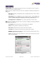
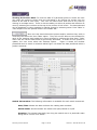
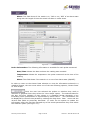
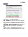
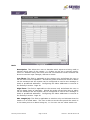
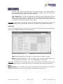
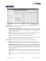
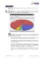
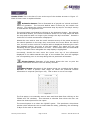
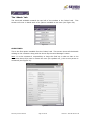
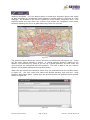
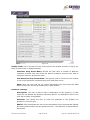
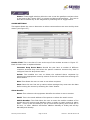
User Manual
INTRODUCTION
Welcome to Seven Eye Limited.
This document is designed to give you an insight into who we are and what we do. It
highlights the people in the team, along with their contact details; should you have an
interest in discovering a little more about the Seven Eye Asset Track and Cool Track
solutions as well as the peripheral devices Seven Eye can provide. It also contains a
User Manual for the Seven Eye web application which allows you to view your asset
tracking and temperature monitoring information from anywhere in the world.
Where the Seven Eye system originated.
The Seven Eye vehicle tracking and remote temperature monitoring system originated
within the portable coldstore division Seven Refrigeration, as they required a wireless
monitoring device that continuously checked the operation of their walk-in freezers.
The idea of this was to identify mistreatment of the unit and capture any faults before
they could seriously damage the refrigeration plant. To this effect an operating system
was developed which could monitor up to 7 temperature probes, 5 switches and 3
relays. The switches were implemented to monitor a number of door switches, defrost
operations and power. The relays allow the monitoring device to interact with the
refrigeration plant through such methods as being able to place the fridge into defrost
remotely.
This system proved such an advantage and with the introduction of GPRS technology
the cost of messaging reduced sufficiently to make the system economically viable.
Seven embarked on the idea that the same technology could be utilised in monitoring
moving vehicles, with or without the temperature aspect. This led Seven Eye to
concentrate on another side of the group’s business, vehicle contract hire. Initially the
system was covertly installed on Seven’s own fleet of spot hire vehicles to monitor
usage as well as positioning should the vehicle breakdown or be stolen. They then
offered it to their existing contract hire customers as a means of reducing costs
through continual monitoring of progress and routes taken.
In 2004 Seven Eye had become too big to remain as part of the refrigeration division
and was set up as a limited company. From that date the business grew significantly
to include customers who had no previous contact with the Seven group. In 2006,
Seven acquired Cold Chain Instruments who design and manufacture the market
leading TranScan range of temperature recorder products. This acquisition enabled the
group to match the synergies of the paper feed temperature recorder market to the
next generation of monitoring devices, ‘Cool Track’. This acquisition led to Seven Eye
re-branding its product range to include ‘Cool Track’ and ‘Asset Track’, for refrigerated
and dry freight applications.
Seven Eye User Manual
Page 2 of 45
Version 1: Issued 06-Dec-06
CONTENTS
•
Page
Contact details ..................................................................10
WEB-BASED APPLICATION USER GUIDE .......................................... 5
•
Logging In ......................................................................... 6
The ‘Open’ Tab ............................................................................. 7
• Maximised ......................................................................... 7
• Units List ........................................................................... 7
o Header field ............................................................. 8
o Specific unit information ..........................................10
o Sensor data ............................................................10
o Viewing the sensor data ............................................11
o Switch information ..................................................11
o Probe information ...................................................12
o View graph..............................................................12
o User configurable coldstore and alarm settings .............13
o CANBus button ........................................................17
• Units Map .........................................................................21
o Header field ............................................................21
o Tracking units map operation ....................................23
• Units Filter ........................................................................25
• Demurrage .......................................................................26
• MDT.................................................................................27
• News ...............................................................................27
The ‘Reports’ Tab.........................................................................28
• Reports ............................................................................28
o Unit selection .........................................................29
o Date selection .........................................................29
o Report selection ......................................................29
o Reporting suite ........................................................29
• Custom Reports .................................................................30
o Vehicle selection ......................................................31
o Customising the report .............................................31
o Requesting the report ...............................................32
The ‘Admin’ Tab ..........................................................................33
• Client Info ........................................................................33
• Waypoints ........................................................................34
• Geofences.........................................................................34
o Header field ............................................................36
o Geofence settings ....................................................36
• Alarm settings ...................................................................37
o Header field ............................................................37
o Alarm details ...........................................................37
The ‘Windows’ Tab .......................................................................39
The ‘Help’ Tab .............................................................................40
• About...............................................................................40
• Symbols legend .................................................................40
• Tool tip.............................................................................41
Frequently Asked Questions ..........................................................43
Seven Eye User Manual
Page 3 of 45
Version 1: Issued 06-Dec-06
Contact Details
Seven Eye operate a 24 hour a day, 365 day a year support service to our customer
base to ensure we provide the best possible level of customer care.
Any member of the team described in this document can be contacted by their email
address shown or by contacting the team from the details listed below.
Seven Eye Limited
Cardinal Court
35 – 37 St. Peters Street
Ipswich
IP1 1XF
Tel No: 01473 261787
Fax No: 01473 212657
Email: [email protected]
Seven Eye User Manual
Page 4 of 45
Version 1: Issued 06-Dec-06
WEB BASED APPLICATION USER GUIDE
The Seven Eye application is an advanced web-based vehicle tracking and temperature
monitoring system that allows its users access from anywhere in the world. Each user
is given a unique, secure login and password which enables them to view all their
system information online.
The web-based application has been developed to be an easily navigated and simple to
use system which the user will master very quickly. In support of this belief we have
written a User Manual which takes the user through each of the functions supported by
the application step by step. We hope this manual will answer all of the questions
which present themselves as you work with the application, however, the support
team(not mentioned in Team section – previously) at Seven Eye are always happy to
help you gain the quickest solution should you run into difficulties. Seven Eye employ
their own team of web developers, research and development and customer technical
support staff who’s aim is to continually improve the quality of the product to the end
user.
Note: This document explains the full range of functionality available to users
however, not all users will have access to all functionality. With this in mind should the
user identify a section of this manual which is not represented on their system they
must be aware that their particular system may not support this level of functionality.
[email protected]
Seven Eye User Manual
Page 5 of 45
Version 1: Issued 06-Dec-06
Logging in
Each user is given a unique login and password which enables them to gain access to
the application at: www.sevengroup.co.uk by clicking on ‘Seven Eye’ then ‘Client Login’
buttons.
Figure 1
Note: A minimum requirement of at least Flash player 8 plug-in is needed to support
this application. To check your version of Flash player, log on to the address listed,
place your cursor on the workspace and ‘right click’. This will open an information
dialogue box which clearly states the Flash version in use. Should your operating
system not be using a suitable version of Flash, this is freely available in download
format from the internet. Logon to http://www.adobe.com/products/ and download
the latest version by selecting the ‘Download’ button and following the instructions.
Figure 2
Once logged in you may be presented with a single or multiple windows as shown
below at Figure 3. For the purpose of this document please close all windows
displayed in the workspace as each of these windows will be covered later in this
document.
Figure 3
Seven Eye User Manual
Page 6 of 45
Version 1: Issued 06-Dec-06
The ‘OPEN’ tab
The first tab available towards the top left of the window is the ‘Open’ tab and this
section covers each of the options available to the user (see Figure 4).
MAXIMISED
Figure 4
This is the first option available to the user from the ‘Open’ tab and allows the user to
hide the Seven Eye Ltd Logo from the top of the browser page, releasing more useable
space.
UNITS LIST
This is the second option available to the user from the ‘Open’ tab. Activation of this
option displays a window showing all the devices monitored under the user’s login (and
selected in the Units List, along with an indication of their last updated status by
means of the icon colour which is explained later in this document. A description of
each of the options and facilities available to the user is listed below (see Figure 5).
Figure 5
Seven Eye User Manual
Page 7 of 45
Version 1: Issued 06-Dec-06
Header Field: This is the bar of icons at the top of the window as seen in Figure 5.
Each of these icons is explained below:
Contracts the viewable content for each unit to display the following information as
in Figure 5.
Unit Type: Coldstore, Refrigerated Trailer, Refrigerated Vehicle, Trailer, Vehicle
(see Figure 5).
Unit Status: This is displayed as one of three colours. Red indicates the
vehicle is parked with ignition off, amber indicates the vehicle has it’s ignition
on but is stationary and green indicates the unit is moving (see Figure 5).
Unit Registration or Identifier: E.g. vehicle registration or driver name.
Expands the viewable content for each unit shown to display the following additional
information (see Figure 6).
Last Update: Date and time the unit information was updated.
Status: Moving, Parked or Stationary (see Figure 6).
Start Time: Indicates the first Journey start time of the day.
Travelled: This relates to the total time the vehicle was in motion.
Stopped: This relates to the time the vehicle has been parked (ignition off) or
stationary (ignition on not moving).
Total: This relates to the total distance the vehicle has moved from the start
time to the last update.
Figure 6
Seven Eye User Manual
Page 8 of 45
Version 1: Issued 06-Dec-06
Allows you to view the user’s units by the following categories:
Name: Shown in alphanumerical order.
In Alarm: Shows the units which are currently in Alarm first.
Status: Views the moving units first, then the stationary units and finally the
parked units.
Customer: If the user has several customers they can view the unit details in
customer alphanumeric order.
ASC: Allows the user to view the details in ascending order.
DESC: Allows the user to view the details in descending order.
Should the user have a large list of units, a specific unit can be selected by its
identifier using the ‘Find’ option. Enter the unit’s individual identifier into the ‘Find
Unit’ field and click ‘GO’. The window will then highlight the selected unit and bring it
to view.
Selecting this icon activates the unit’s filter window which is described later in
this document (see Figure:20).
Selecting this icon activates the Symbols Legend which shows the user the
meaning of each symbol displayed by the application (see Figure 7).
Figure 7
Seven Eye User Manual
Page 9 of 45
Version 1: Issued 06-Dec-06
Specific Unit Information
Selection of this icon will display a screen which shows the Coldstore Sensor Data
for the users chosen unit. This icon will only be displayed and applicable to ‘Cool
Track’ users (see Figure 8).
The Coldstore Sensor Display Window: This window allows the user to view the
switches and probes configured to their system, determine whether they are in alarm
or not and select to view both current and historical data in a number of formats from
the header bar.
Figure 8
Sensor Data: The information listed on this window is described below:
Alarm Status: This field is either in one of two states. If the field is shown as
‘OK’ it is considered to be operating within predefined limits (user configurable).
If the unit is operating outside of these predefined limits then the field will show
a red ‘IN ALARM’ icon.
Description: This field identifies the probe or sensor to which the readings in
the associated columns relate. These are generally made up of a combination
of Supply, Ambient and return probes and various switches.
Time: This field indicates the latest update date and time.
Reading: This field lists the reading measured by the probe or the status of the
switch at the last update.
Alarms Count: This field indicates the number of times the probe or switch
has been in an Alarm state over the last seven days.
Seven Eye User Manual
Page 10 of 45
Version 1: Issued 06-Dec-06
Viewing the Sensor Data: To view the data of a particular probe or switch the user
can select the probe or switch they are interested in by clicking the mouse over the
boxes at the end of each entry. The user can select more than one at any time by
clicking on multiple boxes. There is also the ability to select all probes and switches at
once by selecting the red box at the top of the column of tick boxes. The data selected
can be displayed in either graphical or tabular format by selecting either ‘View Table’ or
‘View Graph’ from the options listed in the header bar.
Once the user has selected the probes and/or switches they wish to
view they can select the ‘View Table’ option. They will now be able to view the data for
each of the switches and probes they have selected by utilising the drop down ‘Table’
menu and the various date fields as previously described. In order for the system to
update, the user must select the ‘Redraw’ option.
Figure 9 shows the window
presented when a switch is selected whilst Figure 10 shows the data presented when a
probe is selected.
Figure 9
Switch Information: The following information is available for each switch monitored.
Date/Time: Shows the date and time the reading was recorded.
Switch State: Shows whether the switch was open/closed or on/off.
Duration: This shows historically how long the switch was in a particular state
along with a current ‘live’ status.
Seven Eye User Manual
Page 11 of 45
Version 1: Issued 06-Dec-06
Alarm: This field shows if the switch is in, ‘ON’ or out, ‘OFF’ of an alarm state
along with the length of time the switch has been in either state.
Figure 10
Probe Information: The following information is available for each probe monitored.
Date/Time: Shows the date and time the reading was recorded.
Temperature: Shows the temperature the probe measured at the time of the
reading.
Alarm: This field shows if the switch is in or out of an alarm state (ON/OFF).
In order to return to the Sensor Data selection or view the information selected in a
graphical format, the user must select one of the two following options; ‘Sensor Data’
or ‘View Graph’
Once the user has selected the probes or switches they wish to
examine in graphical form they select the ‘View Graph’ option. The selected data for
the last 24 hours (default) is then shown in a graphical format alongside a key
illustrating which probe/switch is represented by which colour. This information can
be displayed for various time periods by utilising the drop down `Past:` menu and the
various date fields as previously described. In order for the system to update the
information, after the user has changed any of the search parameters they must select
the ‘Redraw’ option (see Figure 11).
Seven Eye User Manual
Page 12 of 45
Version 1: Issued 06-Dec-06
Figure 11
Probe Information: The various probes are represented by different colours each of
which is identified by the legend displayed alongside the graph.
Switch Information: The switch state is shown in either an on or off condition and is
differentiated by colour.
In order to return to the Sensor Data selection or view the information selected in a
tabular format the user can select one of the two following options; ‘Sensor Data’ or
‘View Table’.
User Configurable Coldstore and Alarm settings: The user is able to adjust the
coldstore and alarm settings to reflect their particular configurations by means of the
Sensor and Bullseye buttons on the header field of the ‘Unit Sensors’ window.
Selecting the ‘Sen’ (sensor) option from the header field displays a window
called ‘Unit Sensor Settings’. This window allows the user to configure the various
switches and probes used by the system at either a ‘Basic’ or ‘Advanced’ level by
toggling the relevant buttons displayed towards the top right of the window (see Figure
12 and Figure 13). (This option is not available with the TS2 product).
Seven Eye User Manual
Page 13 of 45
Version 1: Issued 06-Dec-06
Figure 12 ‘Basic’ View
Basic
Description: This allows the user to describe which inputs are being used to
monitor which parts of the system, i.e. Probes can be set to monitor supply,
return or ambient along with front and rear environments whilst switches can
be set to monitor input voltages, defrosts or doors.
Low Thres: This field is applicable to the sensors only and allows the user to
set the lower limits of operation. Should the probe exceed these limits an alarm
can be activated and the system can be configured to send a text message or
email to predefined addresses. Configuring the Alarm addresses is covered in
the ‘Bullseye’ section. Page 20
High Thres: This field is applicable to the sensors only and allows the user to
set the Upper limits of operation. Should the probe exceed this limit an alarm
can be activated and the system can be configured to send a text message or
email to predefined addresses. Configuring the Alarm addresses is covered in
the ‘Bullseye’ section. Page 20
Max Length (0): This field is applicable to switches only and indicates that the
switch is in a closed state. The user is able to set the time period the switch is
in this state prior to an alarm being set, i.e. the user can set a door switch not
Seven Eye User Manual
Page 14 of 45
Version 1: Issued 06-Dec-06
to alarm until the door has been open for at least 2 hours. This allows users to
open and close doors whilst they work, however, should a door be left open for
an extended period of time it would be alarmed.
Max Length (1): This field is applicable to switches only and indicates that the
switch is in an open state. The user is able to set the time period the switch is
in this state prior to an alarm being set, i.e. if the mains power goes off for over
1 minute then the system can be set to alarm.
Important! Should the user change any of the limits listed in this section they must
select the ‘SAVE’ option to allow the system to reconfigure the settings accordingly.
Advanced
This section allows the user more control of the way in which the data is presented by
means of the additional options explained below.
Figure 13
Type: This field specifies if the input is to be used as a switch or probe.
Model: This field allows the user to specify the use of the switches such as
reverse polarity for example. This is not applicable to the probes.
Important! Should the user change any of the limits listed in this section they must
select the ‘SAVE’ option to allow the system to reconfigure the settings accordingly.
Bullseye: This is located next to the sensor button at the top of the Unit Sensor
window and allows the user to set the alarm configurations (Figure 14).
Seven Eye User Manual
Page 15 of 45
Version 1: Issued 06-Dec-06
Figure 14
Header Field: This is the bar of icons at the top of the window as seen in Figure 14.
Each of these icons is explained below:
Customer Drop Down Menu: Should the user have a number of different
customer accounts they can select the specific customer account they wish to
configure from this drop down menu. This is located at the top left hand side of
the Alarm settings window.
Delete: This allows the user to remove an alarm address from the list by
selecting the appropriate tick box and activating the ‘Delete’ option.
New: This button allows the user to enter a new alarm address.
Save: Once the user has populated or changed any of the details in the address
fields they should activate this option to save the changes.
Alarm Details: These details are configured by the user and described below:
Email: This field allows the user to enter the email addresses of the people who
will receive emails detailing when a probe or switch enters an alarm state.
Mobile Number: This field allows the user to enter the mobile numbers of the
people who will receive texts detailing when a probe or switch enters an alarm
state. There is also the ability to set up rules which specify when texts are to
be sent, i.e. after 1800hrs and before 0800hrs Monday to Friday and all day
Saturday and Sunday.
Alarm Delay: This field allows the user to enter in minutes the time period the
probe or switch is in an alarm state before the system sends an alarm email or
text.
Esc Level: This field is user dependant bespoke setting relating to escalation
levels.
Seven Eye User Manual
Page 16 of 45
Version 1: Issued 06-Dec-06
Active: This field designates whether the alarm address is active (Yes) or
inactive (No).
CANbus Button: This function (if supported) allows the user to view some of
their CANbus information in a graphical format which makes it very easy to view the
general distribution of fuel usage across a user defined period.
Figure 15
Pie Chart: This function allows the user to view the fuel usage as part
of a pie chart as seen in Figure 15. Listed below is a brief description of the
information presented to the user:
Date Fields: These fields have been previously described and allow the
user to define the fuel usage period which the pie chart displays.
Fuel Comparison: This drop down menu allows the user to select any
other vehicle under the customer login and update the pie chart to view
that vehicle’s details.
Totals: The field below the Fuel Comparison drop down menu displays
the total fuel used between the dates selected. This information is
displayed in both Litres and Gallons. It also displays the total distance
travelled in miles and the fuel efficiency in miles per gallon.
Pie Chart: The pie chart illustrates the percentage FUEL used whilst the
vehicle was in various modes of operation i.e. Drive, Cruise, PTO and
Idle.
Seven Eye User Manual
Page 17 of 45
Version 1: Issued 06-Dec-06
Figure 16
MPG Vehicle Comparison Chart: This chart displays the MPG of each
vehicle selected in the Units Filter list in relation to all the other vehicles. It is
primarily used to identify vehicles which are running with a marked degradation
in fuel efficiency for further attention.
Footprint button: Selection of this item allows the user to view a specific unit’s
location history through the Unit History window (see Figure 17).
Figure 17
Seven Eye User Manual
Page 18 of 45
Version 1: Issued 06-Dec-06
Header Field: This is the bar of icons at the top of the window as seen in Figure 17.
Each of these icons is explained below:
Animation Button: This is illustrated as a ‘greyed out’ vehicle and has 2
states of operation. The first and default state is shown by the vehicle icon
moving. This shows the vehicle movements step by step for the day’s activity
in both tabular and graphical form.
The second state is activated by clicking on the Animation button. On selecting
the animation button, the vehicle movement shown on the map stops and both
the map and the table no longer cycle through the day’s activities. Instead a
‘snail trail’ of vehicle movements is displayed.
Should the user wish to view the unit’s activities at any of the points shown by
the vehicle position on the map, they must hover the cursor above the vehicle
icon, the icon is then circled in red and a table is displayed illustrating the unit’s
last updated location, the time of the last update, the speed the unit was
travelling and its general direction of travel. At the same time the associated
entry in the table shown alongside the map display is highlighted.
Conversely, should the user move the cursor over any of the information
displayed in the table towards the right of the window then this will highlight
the corresponding icon on the map along with its positional information.
Printer Button: Operation of this button allows the user to print the
tabular information shown in the Unit History window.
Date Button: Operation of this button brings up a window which allows
the user to enter a specific date range for which the historical location
information is required (see Figure 18). This is done in one of two ways.
Figure 18
The first option is to manually enter a start and finish date from clicking on the
‘FROM’ and ‘TO’ windows. This activates a calendar from which the user can
select the desired period for the report.
The second option is to select the ‘QUICK’ option. This produces a drop down
window which allows the user to select data for today, yesterday, the remaining
5 days of the week or last week.
Seven Eye User Manual
Page 19 of 45
Version 1: Issued 06-Dec-06
To initiate a report from the dates selected by either method the user must
press the update button.
Refresh Button: The user should click this icon to refresh the map to
show the most recent location information.
Post Code Button: The user can press this button to zoom directly to a
map location using a postcode reference.
Pan Button: The user can select this button to pan through the Seven
Eye mapping system. Once selected the user must hold down the mouse
button and drag the mouse to move the map.
Zoom In Button: The user can select this button to zoom in on the
mapping system. Once selected the user must pin point the position where
they would like to zoom and click the mouse button.
The user is also able to zoom in to a specific area from the overall map by
placing the cursor over the top left of the desired area and dragging it down to
the bottom right of the selected area. Once the user releases the left mouse
button the map will zoom in. This can be repeated as many times as is
necessary, until the user reaches the desired level of map detail they require.
Zoom Out Button: The user can select this button to zoom out on the
mapping system. Once selected the user must pin point the position where
they would like to zoom and click the mouse button.
Map Scale Button: This drop down menu allows the user to zoom
immediately to whatever scale they require by selecting one of the options
listed and clicking the mouse button.
Magnify Glass Button: The user can click this button to jump to the exact map
position of the selected unit.
Mobile Data Terminal: Selection of this button allows the user to view the Mobile
Data Terminal (MDT) information (see Page 30). The MDT enables the user to
communicate with the driver by means of the Short Message Service (SMS). The MDT
window displays the following information for the unit selected from the drop down
menu:
Seven Eye User Manual
Page 20 of 45
Version 1: Issued 06-Dec-06
Time: Indicates the time and date the message was sent or received.
Unit: Indicates the Unit the message has been sent to or received from.
Dir: Indicates if the message has been originated from the MDT (IN) whilst
(OUT) indicates the message has originated from the web site.
Message: This field shows the content of the message and can contain up to
140 characters.
Delete: Allows the user to delete the messages they select by means of the tick
box.
UNITS MAP
This is the third option available to the user from the ‘Open’ tab. This option opens a
window which displays all the units under the user’s login on a map background, along
with an indication of their last updated status (see Figure 19). The map automatically
scales to show all vehicles on the users account on a single map page.
Figure 19
Header Field: This is the bar of icons at the top of the window as seen in Figure 19.
Each of these icons is explained below:
Refresh Button: The user should click this icon to refresh the map to
show the most recent location information.
Seven Eye User Manual
Page 21 of 45
Version 1: Issued 06-Dec-06
Post Code Button: The user can press this button to zoom directly to a
map location using a postcode reference. Figure 20 shows the window which is
presented on operation of this function. The user enters the desired postcode
into the relevant box and selects the ‘Go’ button. This automatically displays a
map at the lowest available scale of the immediate area of the postcode.
Note: The two sections of the postcode must be separated by a space otherwise
an error stating ‘Not recognised please try again’ will occur.
Figure 20
Pan Button: The user can select this button to pan through the Seven
Eye mapping system. Once selected the user must hold down the mouse
button and drag the mouse to move the map.
Zoom In Button: The user can select this button to zoom in on the
mapping system. Once selected the user must pin point the position where
they would like to zoom and click the mouse button.
The user is also able to zoom in to a specific area from the overall map by
placing the cursor over the top left of the desired area and dragging it down to
the bottom right of the selected area. Once the user releases the left mouse
button the map will zoom in. This can be repeated as many times as is
necessary, until the user reaches the desired level of map detail they require.
Zoom Out Button: The user can select this button to zoom out on the
mapping system. Once selected the user must pin point the position where
they would like to zoom and click the mouse button.
Map Scale Button: This drop down menu allows the user to zoom immediately
to whatever scale they require by selecting one of the options listed and clicking
the mouse button.
Seven Eye User Manual
Page 22 of 45
Version 1: Issued 06-Dec-06
Tracking Units Map Operation
As a default the unit map will show all the user’s units at the same time on a map
background. It will automatically size the map to give the best resolution available to
show all units in the greatest detail. The user is then able to utilise any of the options
listed in the header field to manipulate the data displayed.
Hovering the cursor above the unit icons displayed on the map will ring the selected
unit with a red circle and bring up an information box displaying the location of the
unit, the last time the data was updated, the unit identifier and the unit’s status.
A single click on any of the unit icons on the map will highlight that particular unit in
the ‘Units List’ window.
A double click on the unit icon activates the ‘Units History’ window which is explained
below:
Header Field: This is the bar of icons at the top of the window. Each of these icons is
explained below:
Animation Button: This is illustrated as a ‘greyed out’ vehicle and has 2
states of operation. The first and default state is shown by the vehicle icon
moving. This shows the vehicle movements step by step for the day’s activity
in both tabular and graphical form.
The second state is activated by clicking on the Animation button. On selecting
the animation button, the vehicle movement shown on the map stops and both
the map and the table no longer cycle through the day’s activities. Instead a
‘snail trail’ of vehicle movements is displayed.
Should the user wish to view the unit’s activities at any of the points shown by
the vehicle position on the map they hover above the vehicle icon they are
interested in. The icon is then circled in red and a table is displayed illustrating
the tracking units last updated location, the time of the last update, the speed
the unit was travelling and its general direction of travel. At the same time, the
associated entry in the table shown alongside the map display is also
highlighted.
Conversely, should the user move the cursor over any of the information
displayed in the table towards the right of the window then this will highlight
the corresponding icon on the map along with its positional information.
Printer Button: Operation of this button allows the user to print the
tabular information shown in the Unit History window.
Date Button: Operation of this button brings up a window which allows
the user to enter a specific date from which they may like to view historical
location information. This is done in one of two ways. The first option is to
manually enter a start and finish date from clicking on the ‘FROM’ and ‘TO’
windows. This activates a calendar from which the user can select the desired
Seven Eye User Manual
Page 23 of 45
Version 1: Issued 06-Dec-06
period for the report. The second option is to select the ‘QUICK’ option. This
produces a drop down window which allows the user to select data for today,
yesterday, the remaining 5 days of the week or last week. To initiate a report
from the dates selected by either method the user must press the update
button.
Refresh Button: The user should click this icon to refresh the map to
show the most recent location information.
Post Code Button: The user can press this button to zoom directly to a
map location using a postcode reference. Figure 21 shows the window which is
presented on operation of this function. The user enters the desired postcode
into the relevant box and selects the ‘Go’ button. This automatically displays a
map at the lowest available scale of the immediate area of the post code.
Note: the two sections of the post code must be separated by a space otherwise
an error stating ‘Not recognised please try again’ will occur.
Figure 21
Pan Button: The user can select this button to pan through the Seven
Eye mapping system. Once selected the user must hold down the mouse
button and drag the mouse to move the map.
Zoom In Button: The user can select this button to zoom in on the
mapping system. Once selected the user must pin point the position where
they would like to zoom and click the mouse button.
The user is also able to zoom into a specific area from the overall map by
placing the cursor over the top left of the desired area and dragging it down to
Seven Eye User Manual
Page 24 of 45
Version 1: Issued 06-Dec-06
the bottom right of the selected area. Once the user releases the left mouse
button the map will zoom in. This can be repeated as many times as is
necessary, until the user reaches the desired level of map detail they require.
Zoom Out Button: The user can select this button to zoom out on the
mapping system. Once selected the user must pin point the position where
they would like to zoom and click the mouse button.
Map Scale Button: This drop down menu allows the user to zoom immediately
to whatever scale they require by selecting one of the options listed and clicking
the mouse button.
UNITS FILTER
This is the fourth option available to the user from the ‘Open’ tab. This option displays
a window showing the various accounts under the user’s login along with the type of
unit, i.e. ‘Cool Track’ (Coldstore, Refrigerated Trailer, Refrigerated) or ‘Asset Track’
(Trailer, Vehicle), their various statuses and alarm states. The user is then able to
select which information they wish to view by selecting one or more of the options
available and clicking the ‘UPDATE’ button (see Figure 22).
Figure 22
Customer: This field shows the user’s customer base.
Type: Coldstore, Refrigerated Trailer, Refrigerated Vehicle, Trailer, Vehicle.
Status:
Active: This indicates the unit is operating correctly.
Inactive: This indicates the unit is not in operation.
No Response: This indicates that communication has been lost from the
unit and may therefore require further investigation.
Powered Down: The unit has been switched off.
Seven Eye User Manual
Page 25 of 45
Version 1: Issued 06-Dec-06
Waiting: The unit is in the process of updating and is waiting for a
response.
Alarm: In Alarm = Yes, Not In Alarm = No
DEMURRAGE
This is the fifth option available to the user from the ‘Open’ tab and relates to the time
used for loading or unloading cargo beyond the contractually agreed lay time for such
an operation. The operator can then be compensated for the time lost. Selection of
this function opens the window shown in Figure 23.
Figure 23
The Demurrage screen illustrates to the user the amount of time their units have spent
at a demurrage location. This information can be printed off in a tabular format by
selecting the print icon. The demurrage locations are set in the ‘Admin’ section of the
application under the ‘Waypoints’ section. It is here the user selects whether they wish
to set a waypoint as a demurrage location or not.
Should the user select a waypoint as a demurrage waypoint, the information is
presented in the demurrage window and includes:
Unit: This relates to the equipment number the unit is fitted to.
Clock: This shows the date and time the equipment entered the demurrage
waypoint.
Elapsed: This shows the length of time the unit has been at the demurrage
waypoint. When the unit has been at a demurrage waypoint for over 3 hours
the block of information is highlighted in red. You will note that in Figure 23
there is a block of data shown as yellow this highlights the information selected
by the cursor.
Location: This shows the location of the demurrage waypoint.
Seven Eye User Manual
Page 26 of 45
Version 1: Issued 06-Dec-06
MDT
This is the sixth option available to the user from the ‘Open’ tab. This option relates to
the Mobile Data Terminal (MDT) which enables the user to communicate with the
driver by means of the Short Message Service (SMS). The MDT window displays the
following information for the unit selected from the drop down menu: (see Figure 24).
Figure 24
Time: Indicates the time and date the message was sent or received.
Unit: Indicates the unit the message has been sent to or received from.
Dir: Indicates if the message has been originated from the MDT (IN) whilst
(OUT) indicates the message has originated from the web site.
Message: This field shows the content of the message and can contain up to
140 characters.
Delete: Allows the user to delete the messages they select by means of the tick
box.
NEWS
This is the final option available to the user from the ‘Open’ tab. The main purpose of
this ‘ticker tape’ display is to give the user confidence that their internet connection
has not been lost and that the information being viewed is live. The news ticker tape
continually updates on a connected site. Should this ticker tape stop it would provide
an indication that perhaps the user’s internet connection may have been lost.
Note: The user is also able to get live news/sport/business news from the Telegraph
website from this function. (See Figure 25).
Figure 25
Seven Eye User Manual
Page 27 of 45
Version 1: Issued 06-Dec-06
The ‘Reports’ tab
The second tab available towards the top left of the window is the ‘Reports’ tab. This
section will cover in detail each of the options available to the user listed within this
section (see Figure 26).
Figure 26
REPORTS
This is the first option available from the ‘Reports’ tab. Selecting this option presents
the window shown in Figure 27 and allows the user to select any of a number of
predefined reports from an extensive reporting suite.
Figure 27
Seven Eye User Manual
Page 28 of 45
Version 1: Issued 06-Dec-06
The left hand side of this window displays all the units selected in the ‘Units list’ and
available to the user, on this particular account. On the right hand side are the report
options.
Unit Selection: The user is able to select one or more units on which to run any of the
reports, contained within the reporting suite, by selecting them from the list of units
displayed. Once selected, these units are highlighted as shown in Figure 27.
Note: The user must select at least one unit to run the report.
Date Selection: The user is able to select the period for which the reports are to be
run by utilising the various date selection options. This is done in one of two ways.
The first option is to manually enter a start and finish date by clicking on the ‘Start
Date’ and ‘End Date’ windows. This activates a calendar from which the user can
select the desired period for the report.
Figure 28
The second option is to select the ‘Past’ option. This produces a drop down window
which allows the user to select data for today, yesterday, the remaining 5 days of the
week or last week. To initiate a report from the dates selected by either method, the
user must press the update button.
Report Selection: The drop down panel allows the user to select the report they wish
to run. The reports can be one of two types; either individual or group (highlighted in
red under the drop down box). The individual report displays the data particular to a
single unit only, i.e. if the user selects an individual report but highlights several units
on which to run the report, the output will be a number of reports, one for each unit
selected. A group report displays the data gathered from a number of units combined
into a single report, i.e. total fuel used for all units selected as opposed to a breakdown
per units.
It must be noted that reports are particular to type (as described previously), i.e.
refrigeration related reports are particular to coldstore and refrigeration monitoring (or
‘Cool Track’) units only whilst fuel consumption reports are particular to tracking (or
‘Asset Track’) units only.
Reporting suite: The reporting suite is constantly evolving as we continue to increase
the range of products and services available.
The following is a list of the type of information currently available to the user within
the various reports:
Seven Eye User Manual
Page 29 of 45
Version 1: Issued 06-Dec-06
•
•
•
•
•
•
•
•
•
•
•
•
•
•
•
•
•
Contact details
Ambient air temperature
Return air temperature
Supply air temperature
Temperature threshold
Power loss
Location
Status
Reading
Door switch
Ignition switch
Journey start
Journey end
Idling
Over-speed
Congestion charge
Fuel level (CANbus)
•
•
•
•
•
•
•
•
•
•
•
•
•
•
•
•
RPM (CANbus)
Fuel rate (CANbus)
Torque (CANbus)
Idle warning
Geofence
Vehicle start time
Vehicle stop time
Vehicle travelled total time
RFID tag unit
Day start and end
Time moving
Time idling
Stopped time
Distance travelled
Engines on/off
Total journeys
CUSTOM REPORTS
This is the second option available from the ‘Reports’ tab. This option allows the user
to request a bespoke report which contains the specific information the customer
requires. See Figure 29.
Figure 29
Seven Eye User Manual
Page 30 of 45
Version 1: Issued 06-Dec-06
The left hand side of this window displays all the vehicles selected in the ‘Units list’ and
available to the user on this particular account. On the right hand side are the report
options.
Vehicle Selection: The user is able to select one or more vehicles on which to run a
custom report by selecting them from the list of vehicles displayed. Once selected
these vehicles are highlighted as shown in Figure 29.
Note: The user must select at least one vehicle to run the report.
Customising the report: The right hand section contains all the components the user
can select to customise the report.
Report Name: A user defined name to call the report.
Report Items: This drop down list presents the user with the available data
which they can select to be contained within their report. As we strive to
continually improve our product range and functions available to the user this
selection will increase. The current options available are:
•
•
•
•
•
•
•
•
•
•
•
•
•
•
•
•
•
Contact details
Ambient air temperature
Return air temperature
Supply air temperature
Temperature threshold
Power loss
Location
Status
Reading
Door switch
Ignition switch
Journey start
Journey end
Idling
Over-speed
Congestion charge
Fuel level (CANbus)
•
•
•
•
•
•
•
•
•
•
•
•
•
•
•
•
RPM (CANbus)
Fuel rate (CANbus)
Torque (CANbus)
Idle warning
Geofence
Vehicle start time
Vehicle stop time
Vehicle travelled total time
RFID tag unit
Day start and end
Time moving
Time idling
Stopped time
Distance travelled
Engines on/off
Total journeys
Start Date: The date from which you wish the report to start (inclusive).
End Date: The date which you wish the report to end (inclusive).
Past: This produces a drop down window which allows the user to select data
for today, yesterday, last week or last fortnight.
Delivery Email: This is the address where you wish the completed report to be
emailed.
Delivery Time: This is the hour of the day you would like the report delivered.
Day: This is the day of the week you would like the report delivered.
Frequency: This is the frequency which you would like the report delivered.
This can be daily, weekly, fortnightly or monthly.
Seven Eye User Manual
Page 31 of 45
Version 1: Issued 06-Dec-06
One-off Report: This allows the user to ask for a single report only which will
be sent as soon as it is available as opposed to any specific time or day.
Requesting the report: Once the required content of the report has been selected by
completing all of the fields listed, this can then be submitted for action by the Seven
Eye team by selecting the ‘Request’ button. This sends an email to the team who will
then develop a bespoke report in accordance with the user’s requirements. This report
will be sent immediately to the customer, should it be a one off report; or at the date,
time and frequency selected in the report request.
Seven Eye User Manual
Page 32 of 45
Version 1: Issued 06-Dec-06
The ‘Admin’ tab
The third tab available towards the top left of the window is the ‘Admin’ tab. This
section will cover in detail each of the options available to the user (see Figure 30).
Figure 30
CLIENT INFO
This is the first option available from the ‘Admin’ tab. This screen shows all the details
relating to the customer along with the Seven Eye Account Manager’s name.
Note: It is the customer’s responsibility to keep this field up to date so that in the
event that Seven Eye need to contact the user (for updates etc.), the correct person is
contacted (see Figure 31).
Figure 31
Seven Eye User Manual
Page 33 of 45
Version 1: Issued 06-Dec-06
WAYPOINTS
This is the second option available from the ‘Reports’ tab and allows the user to define
their own waypoints. These can be used to show place names instead of addresses as
part of the locations returned, i.e. instead of the location being displayed as 12 Smith’s
Street, Ipswich, it can be shown as Seven Asset Depot (see Figure 32).
Figure 32
Waypoints are added by selecting ‘NEW’ from the header bar.
user to enter details into the following fields:
This then allows the
Name: This is the name which you would like to display on the application and
reports when the unit arrives at the waypoint.
Postcode: The waypoint is determined by the Postcode. The Postcode is
entered into this field with the first and second parts of the code being
separated by a space, i.e. IP1 1XF not IP11XF.
Type: The user can enter one of a number of predefined types of waypoints to
enable them to group various waypoints together. Currently, the groups
available are; public house, supermarket, depot, factory, customer, supplier,
marine hazard, road junction, marine buoyage, marina, town, street, site, road
side/motorway.
Demurrage: This allows the user to define a waypoint as a demurrage point.
The default setting for the demurrage waypoints is 3 hours although these are
user configurable.
Once you have set up your waypoints you must select the save option on the header
bar. Should you wish to delete any of your existing waypoints, select the waypoints
you wish to delete by ticking the tick box and then selecting the ‘Delete’ button.
GEOFENCES
This is the third option available from the ‘Reports’ tab. Geofences are electronic
proximity fences around specific locations and the Seven Eye application uses these for
Seven Eye User Manual
Page 34 of 45
Version 1: Issued 06-Dec-06
reporting purposes. The unit detects when it breaks this electronic barrier and sends
an alert message to a predefined email address or mobile phone in the form of a text
message. An example of the use of a geofence is the London Congestion Zone - this
geofence alerts the user when one of their units breaks the congestion zone limits,
therefore allowing the fee to be paid before any fines are incurred.
Figure 33
The geofence option allows the user to set their own geofences (see Figure 33). These
can be either vehicle specific or global. A vehicle specific geofence relates to the
specific unit selected only, whilst if you set up a global geofence, all units under the
users account are configured with this geofence. The user is able to set up 5 vehicle
specific and 5 global geofences through this facility.
When the user selects the Geofence option they are presented with the window shown
in Figure 35. The user must then select the desired tracking unit from the `Units
Selection Drop Down Menu` before they are presented with the geofence input window
shown in Figure 35.
Figure 35
Seven Eye User Manual
Page 35 of 45
Version 1: Issued 06-Dec-06
Figure 36
Header Field: This is the bar of icons at the top of the window as seen in Figure 36.
Each of these icons is explained below:
Customer Drop Down Menu: Should the user have a number of different
customer accounts they can select the specific customer account they wish to
configure from this drop down menu.
Unit Selection Drop Down Menu: The specific unit for which the user wishes
to set up the geofence is selected from this drop down menu.
Save: Once the user has set up various waypoints they must save the data
before exiting the screen by selecting the ‘Save’ button.
Geofence settings:
Description: The user is able to enter a description of the geofence, so that
when the unit breaks the geofence electronic barrier, the description sent to the
user will be easily recognisable.
Postcode: This allows the user to enter the postcode of the location the
geofence is centred upon.
Radius: This field allows the user to set the distance from the postcode defined
previously and therefore set the geofence limits. This distance is represented in
kilometres.
Seven Eye User Manual
Page 36 of 45
Version 1: Issued 06-Dec-06
Status: These toggle switches allow the user to set the geofence to alarm when
a unit enters (IN), leaves (OUT) or enters and leaves the geofence. The user is
also able to delete any of the waypoints by selecting the ‘D’ toggle switch.
ALARM SETTINGS
This option allows the user to determine to whom various alarms are sent and by what
means (see Figure 37).
Figure 37
Header Field: This is the bar of icons at the top of the window as seen in Figure 37.
Each of these icons is explained below:
Customer Drop Down Menu: Should the user have a number of different
customer accounts they can select the specific customer account they wish to
configure from this drop down menu.
Delete: This enables the user to delete the selected alarm recipients by
selecting the appropriate name by means of the tick box and then selecting the
delete button.
New: This allows the user to enter a new alarm recipient.
Save: Once the user has set up various alarm settings they must save the data
before exiting the screen by selecting the ‘Save’ button.
Alarm Details:
Name: This relates to the equipment identifier the alarm is set to monitor.
Email: This is the email address of the person to whom the email is sent.
Mobile Number: This field allows the user to enter the mobile numbers of the
people who will receive texts detailing when a probe or switch enters an alarm
state. There is also the ability to set up rules which specify when texts are to
be sent, i.e. after 1800hrs and before 0800hrs Monday to Friday and all day
Saturday and Sunday.
Seven Eye User Manual
Page 37 of 45
Version 1: Issued 06-Dec-06
Alarm Delay: This field allows the user to enter in minutes the time period the
probe or switch is in an alarm state before the system sends an alarm email or
text.
Esc Level: This field is a user-dependant bespoke setting relating to escalation
levels.
Active: This field designates whether the alarm address is active (Yes) or
inactive (No).
Seven Eye User Manual
Page 38 of 45
Version 1: Issued 06-Dec-06
The ‘Windows’ tab
The fourth tab available towards the top left of the window is the ‘Window’ tab and
shows which windows are active in your workspace. Should the user have several
windows active at the same time, selection of a specific window from this list will bring
this window to the fore and allow the user the ability to immediately manipulate the
data from it.
Figure 38
Seven Eye User Manual
Page 39 of 45
Version 1: Issued 06-Dec-06
The ‘Help’ tab
The fifth tab available towards the top left of the window is the ‘Help’ tab (see Figure
39).
Figure 39
ABOUT
This screen gives the contact details of the Seven Eye team (see Figure 40).
Figure 40
SYMBOLS LEGEND
The symbols legend provides a quick reminder of each of the icons used by the
application (see Figure 41).
Figure 41
Seven Eye User Manual
Page 40 of 45
Version 1: Issued 06-Dec-06
TOOL TIP
Selection of the tool tip allows the user a more interactive help facility. Activation of
this option produces a window which describes each of the icons displayed by the
symbols legend in a little more detail. As the user rolls the cursor across a selected
icon the information displayed changes accordingly (see Figure 42).
Figure 42
Managing the workspace
Hopefully all the information the user needs to operate the Seven Eye application has
been explained in this document. The management of the workspace is individual
preference and the user can fine tune this accordingly.
Suggestion: An easy-to-use workspace layout is to place the ‘Units List’ on the left
hand of the workspace, with the ‘Units Map’ on the right. This will allow the user the
ability to easily navigate the most common functions whilst they establish their own
preferences (Figure 43).
Figure 43
Seven Eye User Manual
Page 41 of 45
Version 1: Issued 06-Dec-06
This manual is designed as a step through guide to help you understanding all the
possibilities of the operating system and its many features and capabilities.
Should you require additional information about the system do not hesitate to contact
us and we will be happy to assist you in realising the full benefits of the Seven Eye
solution.
Seven Eye User Manual
Page 42 of 45
Version 1: Issued 06-Dec-06
FREQUENTLY ASKED QUESTIONS
1. What contract periods are available?
Seven Eye are able to provide contract periods of 36, 48 and 60 months as well as
outright purchase.
2. Who supports the system and from where?
The IT system is supported 24/7 from Seven Eye’s Ipswich head office by a dedicated
team of in-house IT technicians.
3. How many megabytes of data on average are transmitted each month by
each unit assuming temperature and location are logged?
On average, 7mb for a ‘Cool Track’ unit and 4mb for an ‘Asset Track’ unit.
4. Where is the historical data stored and how is this accessed?
All historical information is stored on the Seven Eye dedicated servers based at the
head office in Ipswich and duplicated upon backup servers locally. The information
contained on the servers is easily accessed via the web interface.
5. What training will we receive?
Once operational, Seven Eye will deliver either full or half day training sessions to all
users of the system. This training covers all aspects of the system including mapping,
reporting suite, adding waypoints, geo-fence alerting and ensuring all functionality of
the operating system is fully understood.
6. Are there any telecom requirements for the system and if so what are
they?
Broadband internet access will be required.
7. How does the system gather data?
Data is gathered from on board sensors and interfaces and transmitted to and stored
in Seven Eye dedicated servers based at the head office in Ipswich and duplicated
upon back up servers.
8. Can we import and export data and how is the data formatted?
Yes, import and export of data is available to a variety of other systems in CSV (Excel),
Comma Delimited and Access formats.
9. How does the system interrogate a vehicle?
Utilising the GPRS network Seven Eye enables 24/7 access to vehicle activity and
reporting.
Seven Eye offers a range of polling rates tailored to information
requirements.
10. What computer hardware will I need to run the system?
As the Seven Eye operating system is solely internet-based, no additional PC server
hardware equipment is required. The minimum operating requirements of the Seven
Eye website is Flash player 8, Internet Explorer 6 and broadband connection for speed
of operation.
11. How does the system log and display the specific route the vehicle has
taken on any given day?
The route data is displayed in both graphic and tabular formats on the web application
in the form of a ‘snail trail’ of vehicle movements overlayed on street level mapping. It
is also displayed in the form of a tabular historical record showing date time and
position.
Seven Eye User Manual
Page 43 of 45
Version 1: Issued 06-Dec-06
12. Is the system capable of showing concurrent users?
Yes, Seven Eye's system is capable of displaying, both real-time and historical
information as well as displaying all vehicles or selected group of vehicles on the
screen at the same time. There is no limit on concurrent users.
13. How are the reports per route presented?
We currently offer a full range of reports presenting many details of the vehicle activity
such as location, journey start, journey stop, distance travelled, time taken, maximum
speed, odometer, fuel used, mpg and PTO operation.
14. Can the system produce customised reports and if so how are these set
up?
Yes, customised reports can be requested by the user and initialised by Seven Eye
administration and support functions as required.
15. Can the system alert me when the vehicle is being used out of normal
limits?
Yes, alert messaging via email and SMS to mobile phones are fully incorporated within
the Seven Eye system - including out of hours ignition alerting, driver tampering of
tracking unit, over-speed alerting, alerting outside of geo-fence boundary and overladen vehicles.
16. Does the system support an immobiliser function?
Yes, the system has the ability to remotely immobilise the vehicle via secure login to
the web portal.
17. Does the system support Driver ID Tags?
Yes, the Seven Eye operating system is capable of the identification of drivers through
the use of driver RFID tags. This can be extended to include the ability to unimmobilise a vehicle when the driver is present.
18. Can the system provide default messages and information for drivers in
relation to specific locations and/or dates?
Yes, we can configure the system to send predefined messages to Mobile Data
Terminal’s (MDT’s) at specific times/dates or when a vehicle enters a geofence or
arrives at a waypoint.
19. How does the system alert a driver to the fact that there are messages on
the system and how does the driver respond?
The user can send a message to the driver via the MDT. A ‘new message’ icon is
displayed on the terminal which the driver can then access. Alternatively there is the
option of an in-vehicle voice kit which allows the user to communicate over the air
interface. The driver uses the user interface of the MDT to send a text message back
to the originator and this message is then displayed on the web site. The driver can
also respond to the in-vehicle voice kit by the use of a Press To Talk switch.
20. Does the system have a communications function from base station to
vehicles?
Yes, the Mobile Data Terminal (MDT) and voice kit options provide this function.
The MDT ensures the operator has a two-way text communication channel to enable
text based data to be viewed in conjunction with vehicle location data.
Seven Eye voice kits utilise the GPRS network to enable incoming and outgoing calls.
The built-in voice kit operates like any other hands-free car kit without the need for a
Seven Eye User Manual
Page 44 of 45
Version 1: Issued 06-Dec-06
handset, with the added functionality that any incoming calls can be received but with
the operator restricted to three pre-programmed outgoing numbers.
21. Can the system take readings from the vehicle’s CANbus system?
Yes, Seven Eye can fit a unit which monitors the CANbus information and presents it in
any number of formats.
22. Does the system support Lone Worker Alarming?
Yes, this function is available and incorporates audible and remote alarming.
Operating on a mercury switch basis, when activated (tilted to at least 45 degrees for a
period of up to three minutes) the device will give an audible alarm along with
SMS/email alerts.
23. How often do we receive updates to the web system?
Seven Eye are continually improving the web-based application and as a result there
are regular updates as new features become available to the user. These are currently
provided on a weekly basis.
Seven Eye User Manual
Page 45 of 45
Version 1: Issued 06-Dec-06