1
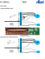
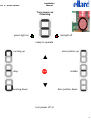
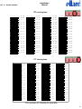
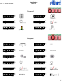
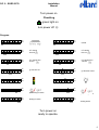
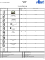
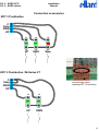
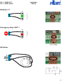
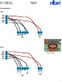
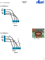
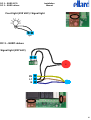
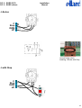
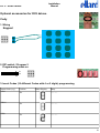
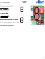
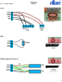
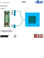
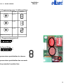
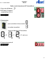
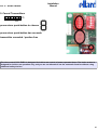
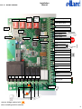
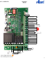
EURO ECO / EURO deluxe DC 2 – EURO ECO DC 2 – EURO deluxe DC 2 Installation Manual DC 2 - Control Unit conforms to DIN EN 12453 Installation Manual Installation Manual DC 2 – EURO ECO DC 2 – EURO deluxe Connection 1-phase 230VAC motor ▼ ▲ power supply C L N PE PE L1 N M ▲ remove bridge when installing build-in-starters connection for build-in-starters ▼ ▲ C L MS N PE power supply PE L1 N 3 DC 2 – EURO ECO DC 2 – EURO deluxe Installation Manual Turn power on Checking red light off green light on ready to operate running up door postion up ▲ stop middle ▼ running down door postion down turn power off ☺ 9 Installation Manual DC 2 – EURO ECO DC 2 – EURO deluxe RT running time 1 2 3 4 5 6 GB 1 2 3 4 ■ ■ ■ ■ ■ ■ On Off Off Off ■ ■ ■ ■ ■ ■ ■ ■ ■ On Off 8“ 7“ ■ ■ ■ ■ ■ ■ ■ On Off 9“ 10“ ■ ■ 10“ 13“ 11“ 16“ ■ ■ ■ ■ ■ ■ ■ ■ ■ ■ ■ ■ ■ ■ ■ ■ ■ ■ ■ ■ ■ ■ ■ ■ ■ ■ ■ ■ ■ ■ ■ ■ ■ ■ ■ ■ ■ ■ ■ ■ On Off 12“ 19“ 13“ 22“ ■ ■ ■ On Off ■ ■ ■ On Off ■ ■ On Off 14“ 25“ ■ ■ On Off 15“ 28“ ■ ■ On Off 16“ 31“ ■ ■ On Off 17“ 34“ ■ ■ On Off 18“ 37“ ■ ■ On Off 19“ 40“ ■ ■ On Off 20“ 43“ ■ ■ On Off 21“ 46“ ■ ■ On Off 22“ 49“ ■ ■ ■ ■ ■ ■ ■ ■ ■ ■ ■ ■ ■ ■ ■ ■ On Off ■ ■ D/F ■ ■ ■ ■ ■ ■ ■ ■ ■ ■ ■ ■ ■ ■ ■ ■ ■ ■ ■ ■ ■ ■ ■ ■ ■ ■ ■ ■ ■ ■ ■ ■ ■ ■ 5 ■ ■ ■ ■ ■ ■ ■ ■ ■ ■ ■ ■ ■ ■ ■ ■ ■ ■ ■ ■ ■ ■ ■ ■ ■ ■ ■ ■ ■ ■ ■ ■ ■ ■ ■ ■ GB 1 2 3 4 5 ■ 6 On Off 23“ 52“ D/F ■ ■ ■ ■ ■ ■ On Off 24“ 55“ ■ ■ ■ ■ ■ On Off 25“ 58“ ■ ■ ■ ■ On Off 26“ 61“ ■ On Off 27“ 64“ ■ On Off 28“ 67“ ■ On Off 29“ 70“ ■ On Off 30“ 73“ ■ On Off 31“ 76“ ■ On Off 32“ 79“ ■ On Off 33“ 82“ ■ On Off 34“ 85“ ■ On Off 35“ 88“ ■ On Off 36“ 91“ ■ On Off 37“ 94“ ■ On Off 38“ 97“ ■ ■ ■ ■ ■ ■ ■ ■ ■ ■ ■ ■ ■ ■ ■ ■ ■ ■ ■ ■ ■ ■ ■ ■ ■ ■ ■ ■ ■ ■ ■ ■ ■ ■ ■ ■ ■ ■ ■ ■ ■ ■ ■ ■ ■ ■ ■ ■ ■ ■ ■ ■ ■ ■ ■ ■ ■ ■ ■ ■ ■ ■ ■ 6 ■ ■ ■ ■ ■ ■ D/F GB On Off 39“ 100“ ■ On Off 40“ 103“ ■ On Off 41“ 106“ ■ On Off 42“ 109“ ■ On Off 43“ 112“ ■ On Off 44“ 115“ ■ On Off 45“ 118“ ■ On Off 46“ 121“ ■ On Off 47“ 124“ ■ On Off 48“ 127“ ■ On Off 49“ 130“ ■ On Off 50“ 133“ ■ On Off 51“ 136“ ■ On Off 52“ 139“ ■ On Off 53“ 142“ ■ On Off 54“ 145“ 1 2 3 4 ■ ■ ■ ■ ■ ■ ■ ■ ■ ■ ■ On Off 56“ 151“ ■ ■ On Off 57“ 154“ ■ ■ On Off 58“ 157“ ■ ■ On Off 59“ 160“ ■ ■ On Off 60“ 163“ ■ ■ On Off 61“ 166“ ■ ■ On Off 62“ 169“ ■ ■ ■ On Off 63“ 172“ ■ ■ ■ On Off 64“ 175“ ■ ■ ■ On Off 65“ 178“ ■ ■ ■ On Off 66“ 181“ ■ ■ ■ ■ On Off 67“ 184“ ■ ■ ■ ■ On Off 68“ 187“ ■ ■ ■ ■ ■ On Off 69“ 190“ ■ ■ ■ ■ ■ On Off 70“ 193“ 5 ■ 6 ■ ■ ■ ■ ■ ■ ■ ■ ■ ■ ■ ■ ■ ■ ■ ■ ■ ■ ■ ■ ■ ■ ■ ■ GB ■ ■ ■ ■ D/F 55“ 148“ ■ ■ 6 ■ On Off ■ ■ 5 ■ ■ ■ ■ ■ ■ ■ ■ ■ ■ ■ ■ CT closing time 1 2 3 4 5 6 AZ 1 2 3 4 ■ ■ ■ ■ ■ ■ On Off Off ■ ■ ■ ■ ■ ■ ■ ■ ■ On Off 5“ ■ ■ ■ ■ ■ ■ ■ On Off 7“ ■ ■ 9“ 11“ ■ ■ ■ ■ ■ ■ ■ ■ ■ ■ ■ ■ ■ ■ ■ ■ ■ ■ ■ ■ ■ ■ ■ ■ ■ ■ ■ ■ ■ ■ ■ ■ ■ ■ ■ ■ ■ ■ ■ On Off ■ ■ ■ On Off 13“ 15“ ■ ■ ■ On Off ■ ■ ■ On Off ■ ■ On Off 17“ ■ ■ On Off 19“ ■ ■ On Off 21“ ■ ■ On Off 23“ ■ ■ On Off 25“ ■ ■ On Off 27“ ■ ■ On Off 29“ ■ ■ On Off 31“ ■ On Off ■ ■ ■ ■ ■ ■ ■ ■ ■ ■ ■ ■ ■ ■ ■ ■ ■ ■ 33“ ■ ■ ■ ■ ■ ■ ■ ■ ■ ■ ■ ■ ■ ■ ■ ■ ■ ■ ■ ■ ■ ■ ■ ■ ■ ■ ■ ■ ■ ■ ■ ■ ■ ■ ■ ■ ■ ■ ■ ■ ■ ■ ■ ■ ■ ■ ■ ■ ■ ■ ■ ■ ■ ■ ■ ■ ■ ■ ■ ■ ■ ■ ■ ■ 5 ■ ■ ■ ■ ■ AZ 1 2 3 4 5 ■ 6 On Off 35“ ■ ■ ■ ■ ■ ■ On Off 37“ ■ ■ ■ ■ ■ On Off 39“ ■ ■ ■ ■ On Off 41“ ■ On Off 43“ ■ On Off 45“ ■ On Off 47“ ■ On Off 49“ ■ On Off 51“ ■ On Off 53“ ■ On Off 55“ ■ On Off 57“ ■ On Off 59“ ■ On Off 61“ ■ On Off 63“ ■ On Off 65“ ■ ■ ■ ■ ■ ■ ■ ■ ■ ■ ■ ■ ■ ■ ■ ■ ■ ■ ■ ■ ■ ■ ■ ■ ■ ■ ■ ■ ■ ■ ■ ■ ■ ■ ■ ■ ■ ■ ■ ■ ■ ■ ■ ■ ■ ■ ■ ■ ■ ■ ■ ■ ■ ■ ■ ■ ■ ■ ■ ■ ■ ■ ■ ■ ■ ■ ■ ■ 6 ■ AZ 1 2 3 4 On Off 67“ ■ ■ ■ ■ ■ On Off 69“ ■ ■ ■ ■ On Off 71“ ■ ■ ■ On Off 73“ ■ On Off 75“ ■ On Off 77“ ■ On Off 79“ ■ On Off 81“ ■ On Off 83“ ■ On Off 85“ ■ On Off 87“ ■ On Off 89“ ■ On Off 91“ ■ On Off 93“ ■ On Off 95“ ■ On Off 97“ ■ ■ 99“ ■ On Off 101“ ■ ■ On Off 103“ ■ ■ On Off 105“ ■ ■ On Off 107“ ■ ■ On Off 109“ ■ ■ On Off 111“ ■ ■ On Off 113“ ■ ■ ■ On Off 115“ ■ ■ ■ On Off 117“ ■ ■ ■ On Off 119“ ■ ■ ■ On Off 121“ ■ ■ ■ ■ On Off 123“ ■ ■ ■ ■ On Off 125“ ■ ■ ■ ■ ■ On Off 127“ ■ ■ ■ ■ ■ On Off 129“ ■ ■ ■ ■ ■ ■ ■ ■ ■ ■ ■ ■ ■ ■ ■ ■ ■ ■ ■ ■ ■ ■ ■ ■ ■ ■ ■ ■ ■ ■ AZ On Off ■ ■ ■ ■ ■ ■ ■ ■ ■ Turn power on. Ready to operate. 11 Installation Manual DC 2 – EURO ECO DC 2 – EURO deluxe Program II ■ 1 ■ 1 ■ 1 ■ 2 ■ 2 ■ 2 ■ 3 ■ 4 ■ 5 ■ 6 ■ 3 ■ 4 ■ 5 ■ 6 ■ 4 ■ 5 ■ 6 ■ 3 ■ On Off keypad On Off external timer On Off 1 ■ 2 ■ 3 ■ 4 ■ 1 ■ 2 ■ 3 ■ 1 ■ 2 ■ 3 ■ 4 ■ 2 ■ 3 ■ 3 ■ 4 ■ 5 ■ 6 ■ 5 ■ 6 ■ 5 ■ 6 ■ 4 ■ 5 ■ 6 ■ 4 ■ 5 ■ 6 ■ 4 ■ 5 ■ 6 ■ 5 ■ 6 On Off transponder On Off on On Off radio control green light Program I ■ 1 ■ 2 ■ 3 ■ 4 ■ 5 ■ 6 ■ 1 ■ 2 ■ 3 ■ 4 ■ 5 ■ 6 ■ 1 ■ 2 ■ 3 ■ 4 ■ 5 ■ 6 ■ 1 ■ 2 ■ 3 ■ 4 ■ 5 ■ 6 ■ 1 ■ 2 ■ 3 ■ 4 ■ 5 ■ 6 ■ 1 ■ 2 ■ 3 ■ 4 ■ 5 ■ 6 ■ On Off on On Off no testing On Off On Off 3 sec. On Off prewarning in-active On Off geba article 505.LS4E.OL 1 ■ 1 ■ 2 ■ ■ 1 ■ 2 ■ 1 ■ 2 ■ 3 ■ 1 ■ 2 ■ 3 ■ 4 ■ 1 ■ 2 ■ 3 ■ 4 3 ■ 4 ■ 5 ■ 5 ■ 6 ■ 6 On Off 8,2k Ω On Off testing active On Off On Off 2 min. On Off prewarning active On Off NC 10 Installation Manual DC 2 – EURO ECO DC 2 – EURO deluxe Turn power on Checking green light on turn power off ☺ Program ■ 1 ■ 2 ■ 3 ■ 4 ■ 5 ■ 6 ■ 7 ■ 1 ■ 2 ■ 3 ■ 4 ■ 5 ■ 6 ■ 7 ■ 1 ■ 2 ■ 3 ■ 4 ■ 5 ■ 6 ■ 7 ■ 1 ■ 2 ■ 3 ■ 4 ■ 5 ■ 6 ■ 7 ■ 1 ■ 2 ■ 3 ■ 4 ■ 5 ■ 6 ■ 7 ■ 1 ■ 2 ■ 3 ■ 4 ■ 5 ■ 6 ■ 7 ■ 1 ■ 2 ■ 3 ■ 4 ■ 5 ■ 6 ■ 7 ■ On Off 1 on On Off On Off On Off CT closing time off CT closing time 30 sec. go function off On Off On Off prewarning in-active On Off testing in-active ■ 1 ■ 2 ■ 2 ■ 3 ■ 4 ■ 5 ■ 6 ■ 7 ■ 3 ■ 4 ■ 5 ■ 6 ■ 7 ■ 4 ■ 5 ■ 6 ■ 7 ■ 5 ■ 6 ■ 7 ■ 6 ■ 7 ■ ■ 1 ■ 2 ■ 1 ■ 2 ■ 3 ■ 1 ■ 2 ■ 3 ■ 4 ■ 1 ■ 2 ■ 3 ■ 4 3 ■ 4 ■ 5 ■ 5 ■ 6 ■ 7 On Off 8,2k Ω On Off CT closing time on On Off CT closing time 120 sec. On Off go function active On Off On Off prewarning active ■ 1 ■ 2 ■ 3 ■ 4 ■ 5 ■ 6 ■ 7 On Off testing active Turn power on ready to operate. 5 Installation Manual DC 2 – EURO ECO DC 2 – EURO deluxe The door control DC 2 EURO is designed for hold to run control of power operated doors. The basic version is designed for hold to run operation only, and you are not allowed to use the automatic function without using additional safety devices. Safety Directions • In case of using DC 2 EURO with a permanent mains connection, an all-pole main switch with an appropriate back-up fuse must be provided. • Before operation, check whether the permissible mains voltage range of the device corresponds to the local mains voltage. • Please note that the door control as well as the motor are for indoor installation only. • During installation, initial operation, maintenance and testing of the DC 2 EURO it is necessary to observe the safety and accident prevention regulations valid for the specific application. Only trained electrical craftsmen should work on electrical equipment. Appliance according to the regulations The door control DC 2 EURO is provided for the operation of sectional-, rollershutter-, folding- and swingdoors. The manufacturer of the complete installation is responsible. He must take care that the relevant standards and guidelines (e.g. DIN 1986, EN 12050) have to be respected. He must take care that a technical documentation of the whole installation is made available. The technical documentation must be added to the door unit. Installation, operating and use of the unit against this manual or the described technical specifications causes danger for persons and produces a liability- and obligations release. National and regional precautions and standards for the installation, as well as safety precautions of local technical standards have to be respected. Technical data Model DC 2 – EURO deluxe DC 2 – EURO ECO Supply voltage 230VAC 4,5VA 230VAC 4,5VA Frequency 50 Hz 50 Hz Protection class IP 54 IP 54 Outputs motor 3x NO relay contact 230 V / 5 A 3 x NO relay contact 230 V / 5 A 2x NO relay contact 230 V / 2 A 1x unregulated supply voltage 1x unregulated supply voltage 24V DC, max. 50mA 24V DC, max. 50mA Wiring 1,5 mm² max. 1,5 mm² max. Operating temperature - 10 C° to + 55 C° - 10 C° to + 55 C° 2 Installation Manual DC 2 – EURO ECO DC 2 – EURO deluxe Table of contents Security instructions and technical data p2 DC – 2 EURO ECO 1-phase 230VAC motor and build-in-starters p3 Layout p4 Programming p5 Optional programming radio control p6 Troubleshooting p7 DC – 2 EURO deluxe 1-phase 230VAC motor and build-in-starters p3 Layout p8 Status display p9 Programming p10-11 Troubleshooting p12 Connection and Accessories for DC – 2 EURO ECO and DC – 2 EURO deluxe Limit switches p13 KDT 2 / M-Series 2T and KDT 3 Pushbutton p14 M-Series 1T, emergency stop / KDT 1 and ES Series p15 J-Series and J-Series with Stop p16 LS 1 and LS 2 Photobeams p17 Safety-edge Pro-Sec-O p19 Connection and Accessories for DC – 2 EURO deluxe only LS 2 and LS 3 Reflector p18 LS 4 Photobeam and 8k2 Ω resistor p19 Signal light 230VAC and Court light 230VAC p20 Cody wiring and programming p21-22 Transponder wiring and programming p23-24 Radio control programming p25-26 1 Installation Manual DC 2 – EURO ECO DC 2 – EURO deluxe troubleshooting Status Display Status red LED Beep Action to take Off No 1, 2, 3, 4 Off No 1, 2, 3 On Yes 7 Off No 1, 2, 3 On Yes 8 On Yes 5 RT error On Yes 1, 2, 3 Safety top barrier Off No 1, 2, 3 On Yes 10 Off No 1, 9 Security active damaged active damaged Relais damaged active Safety top barrier damaged No Power 1 control installation 6 change module 2 control DIP-switch position 7 change safety edge 3 control pre-wired electrical bridges 8 change photobeam 4 control limit switches 9 change fuse 5 contact dealer 10 change the safety top barrier 12 Installation Manual DC 2 – EURO ECO DC 2 – EURO deluxe troubleshooting Status red LED action to take 1x 1, 2, 3 active 2x 1, 2, 3, 7 damaged 3x 4x Off Security RT 1, 2, 3 1, 2, 3 error No power 1,9 1 control installation 6 change module 2 control DIP-switch position 7 change safety edge 3 control pre-wired electrical bridges 8 change photobeam 4 control limit switches 9 change fuse 5 contact dealer 10 change the safety top barrier 7 DC 2 – EURO ECO DC 2 – EURO deluxe Installation Manual Connection Limit Switch open Limit Switch open No Limit Switches (bridged!) Limit Switch close Limit Switch close Prelimit Switch Prelimit Switch ▲ ▲ ▲ Limit Switch open Limit Switch open Limit Switch close Limit Switch close Prelimit Switch Prelimit Switch open remove bridges when installing build-in-starters open close close pre pre 13 Installation Manual DC 2 – EURO ECO DC 2 – EURO deluxe Connection accessories KDT 3 Pushbutton C Stop DWN UP 13 13 21 NO NO NC 14 14 UP 22 DWN Stop KDT 2 Pushbutton / M-Series 2T ▲ C Stop DWN UP remove bridge when installing KDT 3 Pushbutton 13 13 NO NO 14 14 UP DWN 14 Installation Manual DC 2 – EURO ECO DC 2 – EURO deluxe M-Series 1T 13 NO 14 Emergency Stop / KDT 1 21 NC 22 ▲ remove bridge ES Series C Stop DWN UP 15 Installation Manual DC 2 – EURO ECO DC 2 – EURO deluxe Photobeams LS 1 24V GND NC NC 2 3 4 5 1 2 NA NC C - + 1 RX TX - + (NO) LS 2 ▲ 24V GND NC NC remove bridge 2 3 4 5 GND RX 2 VDD - + GND VDD NC N0 C O M 1 - + 1 TX 17 Installation Manual DC 2 – EURO ECO DC 2 – EURO deluxe LS 2 Reflector 24V GND NC NC 1 2 4 3 CND VDD ON CC (NC) RX/TX LS 3 Reflector BU ▲ BN remove bridge Cut BK WH GY - + 24V GND NC NC NC C NO UV UB RX/TX 18 Installation Manual DC 2 – EURO ECO DC 2 – EURO deluxe Court light (230 VAC) / Signal light light DC 2 – EURO deluxe Signal light (230 VAC) Signal S PE L1 N 20 Installation Manual DC 2 – EURO ECO DC 2 – EURO deluxe J-Series C Stop DWN UP 2 P 1 ▲ remove bridge when installing J-Series with Stop J with Stop C Stop DWN UP 2 P 1 21 NC 22 16 Installation Manual DC 2 – EURO ECO DC 2 – EURO deluxe Optional accessories for DC2 deluxe Cody 1. Wiring Keypad 2. DIP-switch / Program 2 Programming mode on ■ 1 ■ 2 ■ 3 ■ 4 ■ 5 ■ On Off 6 3. Insert Codes (10 different Codes with 4 or 5 digits) programming Insert Code (e.g.) Confirm Status Display Beep 1234 ___ ___ 78541 ___ ___ 5398 ___ ___ ... 21 DC 2 – EURO ECO DC 2 – EURO deluxe Installation Manual 4. Programming mode off ■ 1 ■ 2 ■ 3 ■ 4 ■ 5 ■ 6 On Off 5. Cancel Codes ■ 1 ■ 2 ■ 3 ■ 4 ■ 5 ■ On Off 6 press micro push-button to choose press micro push-button two seconds code canceled / postion free 22 Installation Manual DC 2 – EURO ECO DC 2 – EURO deluxe LS 4 24V GND NC NC ▲ remove bridge - + RX - + NC C NO TX 8k2 12V 8,2kΩ SKS ■ GND 1 ■ 2 ■ 3 ■ 4 ■ 5 ■ 6 ■ 7 On Off 8,2kΩ Safety-edge Pro-Sec-O 12V SKS GR BN BN GR RX WH GND WH ■ 1 ■ 2 ■ 3 ■ 4 ■ 5 ■ 6 ■ 7 On Off TX 19 Installation Manual DC 2 – EURO ECO DC 2 – EURO deluxe Transponder 1. Wiring 12V SKS GND IN2 IN1 2. DIP-switch / Program 2 Programming mode on ■ 1 ■ 2 ■ 3 ■ 4 ■ 5 ■ On Off 6 23 Installation Manual DC 2 – EURO ECO DC 2 – EURO deluxe 3. Programming max. 10 different Keys Key Nr. position 1 2 3 Maximum 10 Keys 4. Programming mode off ■ 1 ■ 2 ■ 3 ■ 4 ■ 5 ■ 6 5. Cancel Keys ■ 1 ■ 2 ■ 3 ■ 4 ■ 5 ■ On Off On Off 6 press micro push-button to choose press micro push-button two seconds key canceled / postion free 24 Installation Manual DC 2 – EURO ECO DC 2 – EURO deluxe Radio control (maximum 20 Transmitters) 1. Plug in the RC Module 2. DIP-switch / Program 2 programming mode on ■ 1 ■ 2 ■ 3 ■ ■ 4 5 On Off ■ 6 3. Programming press one button for two seconds (or another transmitter) and so on. Maximum 20 Transmitters. = 10 = 11 ▲ ▲ = 12 and so on. ▲ 4. Programming mode off ■ 1 ■ 2 ■ 3 ■ 4 ■ 5 ■ 6 On Off 25 Installation Manual DC 2 – EURO ECO DC 2 – EURO deluxe 5. Cancel Transmitters ■ 1 ■ 2 ■ 3 ■ 4 ■ 5 ■ 6 On Off press micro push-button to choose press mirco push-button two seconds transmitter canceled / postion free The door control DC 2 EURO is designed for hold to run control of power operated doors. The basic version is designed for hold to run operation only, and you are not allowed to use the automatic function without using additional safety devices. 26 Installation Manual DC 2 – EURO ECO DC 2 – EURO deluxe RT running time Program II Program I CT closing time Limit Switch open Limit Switch close safety module Pre-Limit Switch status display 12 V / brown SKS / green green LED pushbutton radio control GND / white red LED Emergency light module 24 V GND NC NC NC IN2 IN1 IMPULSE C STOP DWN UP OUT 1 N L1 PE PE N L C UP DWN signal light light remove bridge marked with when installing build-in-starters 8 Installation Manual DC 2 – EURO ECO DC 2 – EURO deluxe Program DIP green LED radio control pushbutton Limit Switch open Limit Switch close Pre-Limit Switch red LED 12 V / brown SKS / green GND / white light module Emergency 24 V GND NC NC NC IMPULSE C STOP DWN N L1 PE PE N L C UP DWN UP light remove bridge marked with when installing build-in-starters 4 Installation Manual DC 2 – EURO ECO DC 2 – EURO deluxe Radio control (maximum 20 Transmitters) 1.Plug in the RC Module pushbutton 2.Programming mode on Press button >5 seconds red LED flashes fast 3.Programming Press one button for two seconds red LED red LED flashes long once = stored (or another type of transmitter) and so on. Maximum 20 Transmitters. 4.Programming mode off 10 seconds after the last programming the programm returns to standart mode. 5.Cancel all Transmitters Press button >5 seconds red LED flashes fast press button once more for >5 seconds red LED off = all transmitters cancelled 6 DC 2 – EURO ECO DC 2 – EURO deluxe Installation Manual X DC 2 – EURO ECO DC 2 – EURO deluxe Installation Manual X DC 2 – EURO ECO DC 2 – EURO deluxe Installation Manual X DC 2 – EURO ECO DC 2 – EURO deluxe Installation Manual X