1
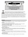
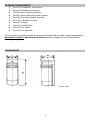
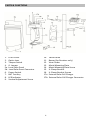
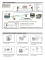
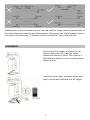
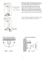
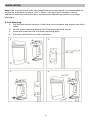
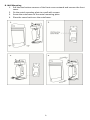
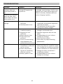
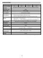
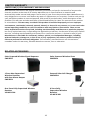
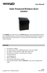
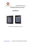
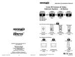
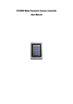
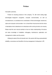
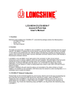
Installation & Operating Manual Solar Powered Wireless Photobeam Sensors SWPB-50 SWPB-100 SWPB-250 SWPB-400 50ft 100ft 250ft 400ft Create a Virtual Wall with the photobeam sensors! FEATURES Detection Range: 50ft / 100ft / 250ft / 400ft (depending on model) Power Consumption: 200uA (fully charged sensors can operate more than 30 days without sunlight) Frequency: 315MHz RF Range: 2000ft / 600m open area Response Time: 50ms Powered by: Copyright © 2012. All Rights Reserved. S-61 / S-62 / S-63 / S-64 R201205-V08 Please read the Manual before attempting to use this product. Disposal of Old Electrical & Electronic Equipment (Applicable in the European Union and other European countries with separate collection systems). This symbol on the product or on its packaging indicates that this product shall not be treated as household waste. Instead it shall be handed over to the applicable collection point for the recycling of electrical and electronic equipment. By ensuring this product is disposed of correctly, you will help prevent potential negative consequences for the environment and human health, which could otherwise be caused by inappropriate waste handling of this product. The recycling of materials will help to conserve natural resources. For more detailed information about recycling of this product, please contact your local city office, your household waste disposal service or the shop where you purchased the product. CAUTION 1. Handle this product with care Avoid any shock or bumping of the product. Improper handling could damage the product. 2. Requires a proper operating environment This product is designed for outdoor use. The allowable temperature range for operation of this product is between -13F ~ 131F / -25C ~ 55C. 3. Check the power source voltage The power source voltage should be within the specified range. (Product must meet the specifications). 4. Objects and liquid entry Never push objects of any kind into this product as this may touch dangerous voltage points of short out parts that could result in a fire or electric shock. Never spill any kind of liquid on the product. 5. Servicing Do not attempt to service this product by yourself as opening or removing covers may expose you to dangerous voltage or other hazards. Refer all service to qualified servicing personnel. 7. Retain Instructions The safety and operating instructions should be retained for future reference. 2 PACKAGE COMPONENTS One (1) Photobeam Transceiver One (1) Photobeam Receiver Two (2) Metal Mounting Plates Two (2) Metal Mounting Plate Screws Two (2) Pole Mounting U-Brackets Four (4) U-Bracket Screws Two (2) Jumpers Two (2) View Finders One (1) Test Paper One (1) User Manual For any returns, please include all components listed above with original packaging in Resalable Condition. Absolutely No Returns will be accepted if any component is missing/damaged. DIMENSIONS Units: mm 3 PARTS & FUNCTIONS 1. 2. 3. 4. 5a. 5b. 6. 7. 8. 9. Front Cover Optics Lens Tamper Switch J1 Jumper Local Solar Panel Local Solar Panel Connector Power Switch BAT Test Key LED Indicator Vertical Adjustment Screw 10. 11. 12. 13. 14. 15. 16. 17a. 17b. 4 Main frame Buzzer (for Receiver only) View Finder Metal Mounting Plate Metal Mounting Plate Screw U-Clamp Bracket U-Clamp Bracket Screws External Solar Cell Charger External Solar Cell Charger Connector APPLICATION DIAGRAM POSITIONS NOT SUITABLE FOR INSTALLATION Don’t install the sensors to an unstable surface. It’s necessary to avoid direct sunlight of sunrise and sunset. Don’t install the sensors in the area where there are seasonal trees growing. Installation position should be suitable for alignment vertical +/-5° horizontal +/- 90° . Don’t install the sensors near corrosive. Don’t soak it in water. It’s necessary to test the system after installation. 5 Multiple sets of the photobeam sensors can be used for longer distance guard.Refer to the above figures to avoid mutual disturbances. When two sets of photobeam sensors are used in the same side, J1 should be short-circuited for one of the two sets. ALIGNMENT Remove the front cover, and turn on the power switch, the LED indicator of the transmitter flashes 3 times. The receiver’s LED indicator flashes 3 times and the buzzer beeps di,di,di. Install the view finder as shown above and push it to the end. Observe at a 45 angle. 6 Make the photo of transmitter/receiver in the center of the view finder by vertical and horizontal adjustment. First adjust the transmitter, then adjust the receiver the beep sound (di,di,di) will be heard when alignment is successful. Put the test paper before the receiver and repeat alignment until the beep sound (di, di, di) can be heard again. Align vertical screw to desire position. After successful alignment remove the view finder, and then install the front cover. 7 INSTALLATION Note: Due to various pole sizes, the installation instruction below is recommended for poles with a diameter of about 1.18” / 30mm. Visit your local hardware store if additional materials are required for mounting the photobeam sensors on a larger sized pole. A. Pole Mounting 1. Pull the two bottom corners of the front cover outward and remove the front cover. 2. Fix the metal mounting plate and U-Clamp bracket with screws 3. Screw the mainframe to the metal mounting plate. 4. Place the cover back over the mainframe. 1. 2. 3. 4. 8 B. Wall Mounting 1. Pull the two bottom corners of the front cover outward and remove the front cover. 2. Fix the metal mounting plate to a wall with screws. 3. Screw the mainframe to the metal mounting plate. 4. Place the cover back over the mainframe. 1. 2. 3. 4. 9 TROUBLESHOOTING Trouble Reason Solution Transmitter LED indicator does not flash when power is on Receiver LED indicator does not flash, and buzzer does not beep when power is on The energy stored is not enough to support the system on. Press “BAT TEST” key to check if there is enough stored energy. IF LED is not lighted, put it under the sunlight and check it next day. Without the front cover, charging is quickly. Detection range is not enough 1. Alignment is not optimum. 2. Stored power is low. False Alarm 1. Confirm proper installation of the viewfinder and optimize alignment with the test paper. 2. This problem can be fixed after sitting out in direct sunlight. 1. Select a firm installation base strong enough to withstand wind. 2. Optimize alignment with the test paper. 3. Let photobeam sit out in direct sunlight to recharge. 4. Clean the front covers. 5. Clear away any object blocking photobeams. 1. The base was not installed properly 2. Alignment is not optimum. 3. Batter power is low. 4. Front covers are polluted. 5. There is some moving object between the transmitter and receiver. 1. The signal of the 1. Because of the reflection, do not transmitter is reflected select long distance model for indoor to the receiver. use. Change the installation positions 2. Other transmitter’s of the transmitter to avoid reflection. signal are interfering 2. Change the other transmitter’s with the receiver. installation position. 3. Battery power is low. 3. Let photobeam sit out in direct sunlight to recharge. Alarm Failure 10 SPECIFICATIONS Model Detection Range Detection Method Response Time Power Input Power Consumption LED Indicator Buzzer Alarm Output Frequency RF Range Tamper Switch Alignment Angel Mounting Operation Temperature Dimension Weight SWPB-50 50ft SWPB-100 100ft SWPB-250 250ft SWPB-400 400ft Twin beam infrared pulse, alarm only when all beams are broken 50ms Solar energy 200uA (the full charged system can work continuously more than 30 days without sunlight) 1. Flash 3 times when power on 2. LED on in alarm condition (Receiver only) 3. Flash 1~9 times when alignment is successful (receiver only) Receiver only 1. Beep “dididi” when power on. 2. Beep “di, di ----“ when alignment is successful, then stop beeping. 3. Beep “di” per 10 seconds when alignment is not successful. Wireless RF Transmission to Wireless Receiver SWPBR 315MHz 2000ft / 600m open area Valid Vertical 10 (+ / - 5 degrees) Horizontal 180 (+ / - 90 degrees) Wall Mounting or Pole Mounting -13F ~ 131F / -25C ~ 55C 2.874” x 3.3465” x 7.0866” / 73mm x 85mm x 180mm 1.4 lbs * Specifications are subject to change without notice 11 LIMITED WARRANTY LIMITED ONE (1) YEAR WARRANTY AND EXCLUSIONS Manufacturer warrants to the original consumer purchaser and not for the benefit of anyone else that this product at the time of its sale by Manufacturer is free of defects in materials and workmanship under normal and proper use for one (1) year from the purchase date. Manufacturer's only obligation is to correct such defects by repair or replacement, at its option, if within such one (1) year period the product is returned prepaid, with proof of purchase date, and a description of the problem. This warrant excludes and there is disclaimed liability for labor for removal of this product or reinstallation. This warranty is voided if this product is installed improperly or in an improper environment, overloaded, misused, opened, abused, or altered in any manner, or is not used under normal operating conditions or not in accordance with any labels or instructions. There are no other implied warranties of any kind, including merchantability and fitness or a particular purpose, but if any implied warranty is required by the applicable jurisdiction, the duration of any such implied warrant, including merchantability and fitness of or a particular purpose, is limited to one (1) year. Manufacturer is not liable for incidental, indirect, special, or consequential damages, including without limitation, damage to, or loss of use of, any equipment, loss sales or profits or delay or failure to perform this warranty obligation. The remedies, provided therein are the exclusive remedies under this warranty, whether based on contract, tort or otherwise. RELATED ACCESSORIES Solar Powered Wireless Signal Repeater SWPREPT Solar Powered Wireless Siren SWSIREN 1 Zone Non-Supervised Wireless Receiver with One Alarm Output SWPREC1 External Solar Cell Charger SWEXCELL One Zone Fully Supervised Wireless Receiver VS-MCR-304 4 Zone Fully Supervised Wireless Receiver VS-MCR-308 12