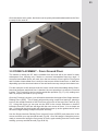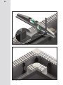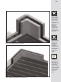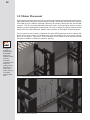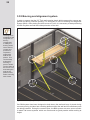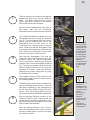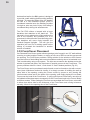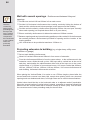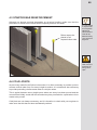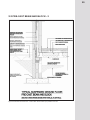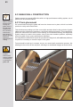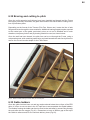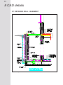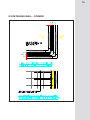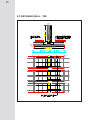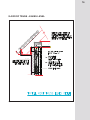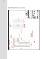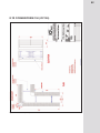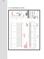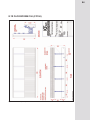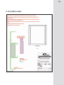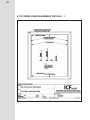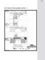
1
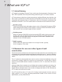
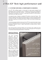
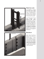
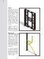
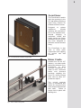
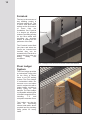
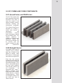
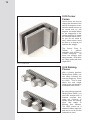
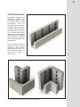
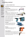
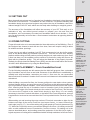
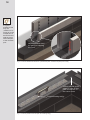
Installation Manual V1
ICF tech
R
advanced construction technology
Insulating Concrete Form
structural walling system
Quick
cost-effective
high performance
sustainable
...the next generation Insulating Concrete Form
installation manual
Consistent with ICF Tech Limited’s (ICF Tech) policy of continuing research and development, we reserve the right to modify or update the
information contained within this or any other material published by ICF Tech. Updates to this manual will be available for download from
the ICF Tech website.
The most up-to-date version of this manual will be available to subscribers or approved installers at www.icf-tech.com
ICF Tech High Performance Wall System and any other marks, drawings or symbols identifying products and/or services of ICF Tech
products are Trademarks or are Copyright belonging to ICF Tech.
ICF Tech assumes no responsibility regarding the use of its products or any other third party product referred to in this document. It is the
full responsibility of the user of these products and any other products mentioned/detailed in this document, to ensure that they are
installed or operated in strict adherence to the manufactuter’s instructions. If training is required for these products then that is the
responsibility of the user, not ICF Tech Ltd. It is further the responsibility of the user to research and understand safe methods of use and
handling of these products and adhere at all times to all Health and Safety and other statutory documents, as applicable.
Preface
ICF TECH WEBSITE AND EMAIL
www.icf-tech.com – please visit for regular updates &
additional product documentation, technical bulletins and other
news. This installation guide and other ICF Tech and related
company information is posted on this website.
[email protected] – please email for additional information or
answers to particular queries.
INSTALLATION GUIDE COMMENTS
Please email us with any comments you may have on the
contents of this document – we aim to keep this guide as
accurate & user-friendly as possible & so your comments are
gratefully received, however minor they may seem.
HEALTH AND SAFETY
To ensure your safety, the safety of your installers and other
trades on the site, ensure that you comply with all required
Health & Safety regulations. If in doubt ask.
KEY ICONS
Refer to this symbol for important information relating to
statutory codes, regulations and material standards.
Refer to this symbol for advice on recycling of your waste
material.
Refer to this symbol for important Health and Safety
advice.
Refer to this symbol for best practice hints.
Contents
1 WHAT ARE ICF’S?
1
1.1 A brief history
2
1.2 Reasons for use over other forms of construction
2
2 ICF HIGH PERFORMANCE WALL SYSTEM
5
2.1 System features and components overview
6
2.2
9
ICF Form and components
2.21 HouseForms and WallForms
9
2.22 Straight forms
11
2.23 Corner forms
12
2.24 Raising pieces
12
2.25 FloorForms
13
3 GETTING STARTED
15
3.1 Hand and power tools
16
3.2 Setting out
17
3.3 Form cutting
17
3.4 Form placement from foundation level
17
3.5 Form placement from ground floor
23
3.51 Rebar placement
26
3.52 Bracing and alignment system
28
3.53 FormCloser placement
30
3.54 Lintols over and around openings
32
3.55 Simpson strongtie ledger placement
33
3.6 Concrete placement
36
3.61 Concrete boom pumps
37
3.62 Bottom-up pumping
37
3.63 Pre-Concrete pour checklist
38
3.64 Post-Concrete pour checklist
39
4 PRINCIPLES OF REINFORCEMENT
41
4.1 Spliced joints in reinforced concrete
42
4.2 Rebar placement
42
4.4 Starter bar placement
46
4.5 Cold joints
46
5 FLOORS
48
5.1 Precast beam and block - 1
49
5.2 Precast beam and block - 2
50
5.3 Ground bearing slab - 1
51
5.4 Ground bearing slab - 1
52
5.5 Pre-cast concrete plank - 1
53
5.6 Pre-cast concrete plank - 2
54
5.7 Hanson jet floor- 1
55
5.8 Hanson jet floor - 2
56
5.9 Timber suspended ground floor
57
6 CONSTRUCTION AT ROOF LEVEL
60
6.1 Wall plate fixing
61
6.2 Rafter feet connection
62
6.21 Trussed rafters
62
6.22 Cut roofs
62
6.3 Gable wall construction
63
6.31 Form placement
62
6.32 Bracing and cutting to pitch
64
6.33 Gable ladder
64
Contents
7
7.1
7.1
OTHER CONSTRUCTION
Basement construction
Tee wall
68
69
73
8
CAD DETAILS
72
9
FORM SPECIFICATIONS
102
10 PRODUCT CODES AND DESCRIPTIONS
106
Revision status
Revision
Date
0
First issue - version 1.0
28/06/09
1
Refererences to ‘fall arrest’ changed to ‘fall restraint’
21/09/09
2
Page 85, correction to diagram description
21/09/09
Diagrams and Tables
DESCRIPTION
Fig
Page
1
Interlock design and witness lines
6
2
Waterbar webs used with HouseForms and WallForms
7
3
Waterbars used in FloorForms to provide a vertical slurry barrier
7
4
Web, embedded into the Forms during manufacture
8
5
Bracing and Alignment system
8
6
FormCloser with installation support fitted
9
7
Rebar cradle showing lintol
9
8
Showing FormLok secured to trench block and FloorForm attached
10
9
Showing FloorLedger embedded into the concrete core
10
10
HouseForm and WallForm forms
11
11
Straight Forms
11
12
Corner Forms
12
13
SIRPs & DIRPs
12
14
FloorForms
13
15
Internal Corner FloorForm and External Corner FloorForm
13
16
18
17
FormLok installed with FloorForm pressed into place - levelled if required
prior to fixing
FormLok position at corners plus use of setting-out jig
18
Levelling the corners
19
19
Form attached to the FormLok
19
20
Placing waterbars as the installation proceeds
20
21
Placing the FloorForms from the corner out
20
22
Detail of telescopic vent installation
21
23
Telescopic vents installed ready for the beams to be placed
21
18
DESCRIPTION
Fig
Page
24
Detail of liquid DPC
22
25
Beams being installed
22
26
Beams and block floor ready for the next lift of forms
23
27
Determining the height of the SIRP
24
28
SIRPIC in place
24
29
SIRPs installed and corner form installed
25
30
Straight forms installed away from the corner form
25
31
Detail of rebar located in the web
26
32
Detail of rebar overlap-splice
26
33
Diagram showing where cut forms should NOT be positioned
27
34
9mm ply used to reinforce cut form
27
35
Detail of Bracing & Alignment system installed
28
36
Detail of window clip
30
37
FormCloser being installed as ICF wall is erected
31
38
FormCloser with bracing and vent holes
31
39
32
40
Detail at the top of the window to show FormCloser, rebar cradle and rebar
lintol
Typical rebar placement around openings
41
Example of loading calculation to determine the no. of ledgers
33
42
Floor Ledger inserted into the Form ready for the concrete core to be filled 33
43
FloorLedger detail showing fixing screws
34
44
Detail of fixing arrangement when using cassette floor systems
35
45
Concrete pouring using a double S reducer
36
46
Bottom-up pump assembly
37
32
Fig
DESCRIPTION
Page
47
Detail of starter bar reinforcement
46
48
49
50
50
Precast beam and block floor – section taken where beams span on to
ICF wall
Precast beam and block floor – section taken where beams span parallel
to ICF wall
Typical Ground Bearing Slab
51
Typical ground bearing slab with level threshold
52
52
53
53
Precast concrete plank – section taken where planks span parallel to ICF
wall
Precast concrete plank – section taken where planks span on to ICF wall
54
Hanson Jetfloor - section taken where planks spans parallel to ICF wall
55
55
Hanson JetFloor – section taken where beams span on to ICF wall
56
56
Typical timber suspended ground floor
57
57
Detail of wall plate and FormLok at roof level
61
58
Detail of Roof Truss and Wall Plate
62
59
Forms built-up next to roof truss prior to cutting
63
60
Gable end wall showing cut forms ready for concrete pour
64
61
Detail of Gable Ladders
65
62
Detail of gap in FormCloser at top of Gable Wall
65
63
Preferred arrangement for forming ‘T’ walls
70
64
Rebar and tie-wire detail
70
65
Retaining wall - basement
73
66
Retaining wall - corner
74
67
Retaining wall - tee
75
68
Roof truss - eaves level
76
69
Raised collar - eaves detail
77
49
51
54
Fig
DESCRIPTION
Page
70
Truss roof
78
71
HouseForm 100mm (SF100)
79
72
WallForm 150 (SF150)
80
73
CornerForm 100 (CF100)
81
74
CornerForm 150 (CF150)
82
75
FloorForm 100 (FF100)
83
76
FloorForm 150 (FF150)
84
77
FloorForm ext. corner (FFEC100)
85
78
FloorForm ext. corner 150 (FFEC150)
86
79
FloorForm int. corner 100 (FFIC100)
87
80
FloorForm int. corner 150 (FFIC150)
88
81
Rebar Cradle
89
82
FormCloser
90
83
FormCloser assembly details - 1
91
84
FormCloser assembly detail - 2
92
85
Detail for vertical tile hanging
93
86
Hanson Jetfloor - section taken where planks spans parallel to ICF wall
94
87
Hanson Jetfloor - section taken where planks spans parallel to ICF wall
95
88
Hanson Jetfloor - section taken where planks spans parallel to ICF wall
96
89
Hanson Jetfloor - section taken where planks spans parallel to ICF wall
97
90
Hanson Jetfloor - section taken where planks spans parallel to ICF wall
98
1
What are ICF’s
2
1 What are ICF’s?
1.1 A brief history
ICF stands for Insulating Concrete Forms, which were first developed in Germany in the
Late 1950’s by BASF, their first product being called the “Igloo” for obvious reasons.
ICF’s have been a viable form of wall construction in mainland Europe since that time, but
have come to prominence in North America and Canada over the last 15 years to be a
recognised and respected form of Construction, with over 50 makes in production and
estimates of between 7 and 12% market share for domestic house construction alone.
systems
» BLOCK
These are modular blocks with either polymer, steel or Expanded Polystyrene (EPS)
webs holding parallel sheets of EPS together, forming a hollow block which is filled
with concrete, once a certain height has been reached.
» PLANK systems
Which are similar to BLOCKS as they have parallel EPS walls, but these are held
together with rails and wall ties which are not moulded into the EPS walls during
manufacture, as those above which use polymer or steel webs. Quadlock is an
example of such a PLANK system.
» PANEL systems
Similar to BLOCK systems but made in much larger formats, typically
2.4m. in height by 1.2m. wide.
1.2 Reasons for use over other types of wall
construction
The Governments commitment to the Kyoto Accord has meant the ever-increasing need
for higher levels of thermal insulation requirements which has seen “U” values (a measure
of a building components Thermal Transmittance) increase year on year since the late
1990’s.
The “U” values for external walls have risen to such an extent that traditional cavity wall
construction is finding it difficult to meet the new requirements – already with a 100mm
cavity to accommodate thicker insulation to achieve a 0.35 “U” value with 0.25 values
imminent.
Although timber frame systems are not finding the increased regulations too taxing, the
advantage ICF’s have over this form of construction is lead-in times, as typically a timberframed solution will take three to four months to design and deliver to site, whereas an
ICF is ready to be delivered ex-stock.
Our ICF HouseForm has a “U” value of 0.19 using normal pumped concrete, and can
easily achieve 0.11 by using insulated plasterboard instead of the normal 12.5mm
plasterboard, yet only 348mm thick!
3
ICF’s also have very high levels of air-tightness, an issue which is being given even higher
importance than thermal efficiency, as the air-leakage from buildings through airexfiltration takes with it more hot air than that lost through the walls due to thermal
inefficiency, and thus is adding to the carbon-load placed on the heating system to replace
the lost heat, due to the requirement to burn more fossil (or carbon) based fuels.
ICF’s due to their monolithic concrete core are inherently air-tight, especially when
combined with our FormCloser system around structural openings. The ICF Tech system
can achieve air infiltration figures as low as 0.74m3/m2/hr @ 50Pa.
2
The ICF Tech high performance wall
6
2 The ICF Tech high performance wall
2.1 SYSTEM FEATURES & COMPONENTS OVERVIEW
The ICF Tech walling system is the result of many years research and
development and is currently the only ICF designed in the UK for the UK domestic
and commercial construction sectors. It has been designed specifically to
seemlessly use all types of concrete or lightweight flooring and roofing systems,
even down to full width void vents.
Our approach was to design a complete ICF system, not just the Forms. This
means we supply every component required to get you from the foundation to the
roof plate with ease. The system hosts many features to make building with ICF’s
even more enjoyable and combine to help you finish your project professionally,
and safely.
The following pages detail the features of the ICF Tech system that make it stand
out from imported systems from overseas and why it is the choice for serious
developers looking to gain a higher specification building solution without
increasing costs.
From the any-way-up interlock design to the innovative way in which any floor
thickness can be accommodated, you will see why choosing the ICF Tech system
is a safe bet towards high performance construction.
Interlock Design
and witness lines
The most noticeable
difference with our
system is the interlock –
designed to provide a
slurry-proof seal and
friction fit ensuring that
your bedding joints do
not leak or float apart
when being filled with
concrete. There is no
face-out or top/bottom,
just pick it up and lay it
and with a 25mm
interlock repeat, you can
save on waste and
adapt existing plans with
more accuracy. Witness
lines on the face of the
forms ensure accurate
on-site cutting and show
where you can fix to.
Firring strip
witness line
Interlock repeat witness line
Centre witness line
Fig 1 - Interlock design and witness lines
7
Waterbar webs
Pushed down
into the Form
The perpend or vertical
joint of the Forms of any
ICF block are a weak
area. If unsupported the
pressure of the concrete
can force these perpends
apart and cause a blowout if you are not careful.
To overcome this, the ICF
Tech
System
was
designed with higher
density EPS to give an
increased tensile strength,
but we also designed the
Waterbar web which acts
both as a vertical barrier to
concrete slurry and also to
strengthen the perpends
by helping to resist the
pressure of the concrete
acting on the unsupported
EPS panels.
Fig 2 - Waterbar webs used with HouseForms and WallForms
Pushed down
into the Form
Waterbars
When using FloorForms
there is no need for a
waterbar web. To stop
slurry seepage at the
vertical junction between
forms, we have designed
a waterbar with a zigzag
design that increases the
surface area of the plastic
as it slide fits into purpose
moulded channels at the
ends of the Forms.
Fig 3 - Waterbars used in FloorForms to provide a vertical slurry barrier
8
Webs
Embedded at 300mm
centres into the Forms our
webs have been designed
for
maximum
fixing
strength, and have also
been
designed
to
accommodate
UK
standard rebar sizes,
when required and have a
snap-in clip for horizontal
rebar placement. We also
have the only full height
vertical
corner
web,
ensuring full-height, right
to the corner fixing on
external and internal
corners.
Designed to hold up to
with
a
64kg/m2
comfortable factor of
safety and an incredibly
strong pull-out resistance
so screws stay firmly fixed.
Fig 4 - Web, embedded into the Forms during manufacture
Bracing &
Alignment System
Our
lightweight
demountable
system
conforms to the current
Work
at
Height
Regulations 2005 No. 735
and is designed to both
brace and plumb the ICF
wall against wind loading
and
during
concrete
pour/cure. It also provides
a safe working platform for
form
and
concrete
placement.
A
simple
turnbuckle
design moves the top of
the wall in or out so that
checks prior to, and after,
the concrete pour ensure
that the wall remains
perfectly plumb, and
perfectly straight.
Fig 5 - Bracing and Alignment system
9
FormCloser
The FormCloser is used to
seal the openings in the
ICF wall whilst providing a
rapid fixing solution for
window and door frames.
Designed
to
replace
subframes
thereby
reducing site operations.
Due to its insulated core,
thermal
bridging
is
minimised. Health and
Safety issues are further
addressed as the system
has been designed to
facilitate internal window
fixing.
The FormCloser is also
used to finish gable
construction and capping
off vertical end wall
sections.
Fig 6 - FormCloser with installation support fitted
Rebar Cradle
Another first for the ICF
Industry – our rebar cradle
twists into the back of our
FormCloser
to
allow
accurate placement of
rebar to form reinforced
lintels over structural
openings negating the
need for factory-formed
lintel units as some ICF
producers require.
The correct concrete
cover is maintained and
allows for complex lintols
to be designed and placed
with ease.
Rebar is
simple held in place with
twisting wire.
Fig 7 - Rebar cradle showing lintol
10
FormLok
The key to the success of
any building project is
accurate setting-out. This
is never truer than when
setting out the first course
of
forms
from
the
foundation. Our FormLok
is a simple yet effective
means of providing a fixing
for the form whilst also
providing an accurate
means of setting-out the
perimeter of the wall.
FormLok
The FormLok is shot fired
into place and when the
Forms are inserted and
levelled they can be
screwed to the FormLok to
ensure that they stay put
during
windy
site
conditions.
Fig 8 - Showing FormLok secured to trench block and FloorForm attached
Floor Ledger
System
The Floor Ledger provides
a mechanical fixing point
for the fixing of timber
floors to our ICF walling
system. The Floor Ledger
is embedded within the
concrete core and when
used in conjunction with a
timber ledger, provides a
strong fixing for joist
hangers. The Floor Ledger
is compatible with all types
of timber/composite floors,
including
TJI
and
composite cassette floors.
FloorLedger
The Ledger can also be
used
for
connecting
internal stud walls, where
required and for providing
fixing points for heavy
loads.
Fig 9 - Showing FloorLedger embedded into the concrete core
11
2.2 ICF FORMS AND FORM COMPONENTS
2.21 HouseForms and WallForms
The ICF Tech system has
been designed around two
structural core sizes to
meet the needs of two
distinct building sectors;
domestic housing and
commercial properties.
The 100mm HouseForm is
designed for building 3
storey town houses or
apartments
with
intermediate
concrete
floors, yet creates a wall as
little as 250mm thick. The
150mm
WallForm
is
suitable for building larger
apartment blocks and
commercial buildings and
its concrete core size
makes it suitable for party
wall
construction.
Fig 10 - HouseForm and WallForm forms
2.22 Straight Forms
All straight forms measure
1200mm long by 450mm
high and a width of just
250mm or 300mm. Each
EPS panel is 75mm thick
and made from 30g/ltr EPS.
Each form has external
markings to show where the
form can be cut to maintain
the interlock integrity - every
25mm. A horizontal witness
line also gives guidance
when the form needs to be
cut horizontally.
An
embossed area, 44mm x
440mm indicates where
fixing screws can be used to
attach internal or external
cladding/material. These
are arranged 150mm from
the ends and then at
300mm centres.
Fig 11 - Straight Forms
12
2.23 Corner
Forms
Corner forms are used to
change the direction of the
wall by 90 degrees. As our
interlock allows the form to
be turned over by 180
degrees, the shape allows
for the staggering of the
vertical coursing to create
the stretcher bond effect,
so you do not need to
worry about which hand
the form is, so long as you
maintain the stagger.
The Corner Form is
725mm
x
425mm
externally and 475mm x
175mm internally.
All
forms are 450mm high
when bonded. EPS skins
are 75mm and made from
30g/ltr EPS.
Fig 12 - Corner Forms
2.24 Raising
Pieces
With a Double Interlock
Raising Piece (DIRP) you
can easily increase the
coursing height by 75mm
at a time. This is used
where the wall height
needs to be increased by
a standard brick course.
Fig 13 - SIRPs & DIRPs
By using a Single Interlock
Raising Piece (SIRP) you
can build straight from a
finished concrete floor
using the FormLok to
quickly place the raising
piece and adapt to
differing floor finishes.
The SIRP comes as a
standard 100mm high unit
and can be cut to suit the
finished floor level.
13
2.25 FloorForms
As the name suggests, the
FloorForm creates the
structural platform ready
to receive heavy floor
construction such as
concrete beam and block,
precast concrete hollowcore floors, and composite
steel/concrete floors due
to it’s corbel area, which
unlike other ICF’s does not
protrude from the internal
face of the form, so can be
used in intermediate floor
construction.
The FloorForm comes in
straight, as well as corner
variants for both internal
and external corners. As
with the straight forms, it
has either a 100mm or
150mm core.
Fig 14 - FloorForms
Fig 15 - Internal Corner FloorForm and External Corner FloorForm
3
Getting started
16
3 Getting started
3.1 HAND & POWER TOOLS
Care must be
taken when
using hand and
power tools.
Ensure that you
have been
given adequate
training and
instruction
before using
any tools.
Ensure that the
correct PPE is
provided and
worn at all
times.
IF IN DOUBT
DO NOT USE
THE TOOL!
Erecting an ICF wall does require the use of some specialist tools, although the majority
are non-specialist. In order to further increase wall erection times, we use of the following
specialist tools;
Hot wire table
‘Block Buddy’ The quickest and easiest way to cut your
forms to length. With a long stroke (600mm) and the
ability to cut complex angles, this tool makes clean
work of accurately cutting the EPS Forms.
Saws
Cutting EPS and the polypropylene webs is easily
accomplished using a sturdy hand saw such as the
Stanley Fat-Max range. Use of a smaller ‘wall
board’ saw is also recommended for smaller
cuts. Reciprocating saws can also be used.
Combi, masonry drills & impact drives
With the capacity to drill and
hammer, these drills make light
work of fixing the Bracing and
Alignment system to the deck as
well as other site-fixing jobs.
Rechargeable and with a long
battery life, these are an essential
part of the installation kit.
Hot knife
The perfect tool for chasing the EPS wall to
make service conduits for electrical cables
and fittings and plumbing pipes etc. Use
with a sled to ensure correct depth of cut.
Nail gun
For quick and accurate fixing of the FormLok
and other items into concrete or other hard
materials use a gas cartridge nail gun.
Foam adhesive
For fixing the bottom of Forms to the substrate if not using
the FormLok and for closing any gaps and glueing cut
forms. in the wall prior to the concrete pour. We
recommend the use of a foam gun as opposed to foam
cans, as they are more accurate to place, more costeffective and are easier to clean.
17
3.2 SETTING OUT
Most domestic structures can be founded on foundations designed using Approved
Document A1/2 Section 2E – Foundations of Plain Concrete. It is worth mentioning that
foundation design by a structural engineer may reduce the size of foundation, due to the
reduced weight of the ICF wall, which can also help when building on marginal ground.
Refer to
Approved
Document A
The accuracy of the foundations will effect the accuracy of your ICF Tech wall, so it is
advisable to only use skilled ground workers to prepare your site and form the
foundations, as it is necessary to create level foundation which do not deviate +/- 5mm
over 3m and generally not more than +-5mm between levels taken at opposing sides of
the building.
3.3 FORM CUTTING
Forms will need to be cut to accommodate the linear dimensions of the Building. Even if
the Designer has chosen to work with our form sizes, forms will require cutting to allow
for window and door openings.
Forms may be cut with a handsaw, but ICF Tech recommend a hot wire knife system
such as the Block Buddy by Demand Products Inc. This site tool acts as a working
platform whilst cutting and will produce perfectly straight cuts, each and every time. Once
a form has been cut, the waterbar recess needs to be formed by using the Groove Jet
fitted with the Waterbar profile. This will allow the Waterbar to be properly inserted.
Similarly, the Single Interlock Raising Piece (SIRP) can also be cut with either the Groove
Jet with a knife attachment or by using the Block Buddy.
3.4 FORM PLACEMENT - From foundation level
For the following examples we will assume that the build will progress from a standard
strip foundation and not from a cast slab. Because of the difficulties in establishing a
suitably level strip foundation, remember you need +/- 5mm over 3m, we recommend
that trench block is used as it is easier for the correct level tolerance to be established and
maintained.
When building a concrete first floor, be it beam and block or cast slab or other systems
such as Hanson Jetfloor, we use a first course of FloorForm as this will accommodate any
type of ground floor system available. Once the trench block has been built to the correct
level, ensuring that the top of foundation level to formation level of the ground floor
equates to the height of the trench block plus the corbel of the FloorForm ) the first step
is to secure the FormLok to the trench block simply by shot firing. It is not usually
necessary to level the FormLok with shims, or the base of the Forms themselves, as most
irregularities in level can be removed when the Form is pushed into the FormLok (see Fig
16).
When setting out and securing the outer section of FormLok, remember to allow for the
inside curved face of the corner FloorForm (and corner forms), i.e. leave 125mm from
each edge (see Fig 17). Use of the setting-out jig will speed-up FormLok placement (Fig
17). When the FormLok is secure you can start fitting the first form. All setting out should
start, as with traditional forms of construction, from the corners. By setting out in the
manner described above, and working around the perimeter of the wall (left to right), a
logical sequence of cutting will be established which will help maintain a level first course.
always cut to
the witness
lines otherwise
your
subsequent
course of
Forms will not
interlock
properly.
Remember to
cut the slot for
the last
waterbar in the
end of the cut
form – this is
easily achieved
using a hot
knife or
reciprocating
saw.
When
constructing the
ICF wall, DO
NOT use
batches of
Forms that are
more than two
manufacturing
weeks apart
from each other
due to settling
dimensional
changes.
18
It is good
practise to use
only one
‘outside’ run of
FormLok on the
outside skin of
the EPS and to
seal any gaps
with foam prior
to the concrete
pour.
Adjust horizontal level
by raising or lowering
the Form
Fig 16 - FormLok installed with FloorForm pressed into place - levelled if required prior to fixing
125mm gap left at the
edges to allow for the
inner curved face of
the corner forms
FormLok setting-out jig
Fig 17 - FormLok position at corners plus use of setting-out jig
19
It is recommended that spot-levels are taken at each corner to find which is the highest,
as all form placement is set-out from the corners. The lowest corners can then be raised
within the FormLok to the desired height, which should be no more than 5mm if the
foundations have been laid correctly. If greater irregularities occur, you can bed the
FormLok on to mortar and shot fire once the mortar has set. Alternatively, use plastic
shims below the FormLok, shot firing though the shims to secure the FormLok and
maintain level. To save time and effort, make sure your ground worker is accurate.
Fig 18 - Levelling the corners
Once the Corner Forms have been placed and fixed to the FormLok (Fig 18), work from
the corners, placing FloorForms working toward the corners (Fig 21), remembering to
place the Waterbar in each vertical joint (perpend) as placing proceeds (Fig 20). As your
foundation has already been set-out to ICF Tech sizes, any cut forms required to complete
a straight run of Forms will be made along one of the vertical witness lines that denote
the interlock repeat (25mm centres).
Form secured to
the FormLok by
screwing into the
firring piece
Fig 19 - Form attached to the FormLok
20
On the short
side of the
FormLok, don’t
forget to cut the
waterbar to the
correct length.
Waterbars
Fig 20 - Placing waterbars as the installation proceeds
Fig 21 - Placing the FloorForms from the corner out
21
Once the FloorForms are installed and secured (with screws) to the FormLok, determine
the location and position of the vents and install them. Care must be taken to liaise with
the flooring contractor or supplier to ensure the correct location of the vents. Figs 22 &
23 show the telescopic vents installed prior to filling the FloorForms with concrete.
Depending upon the type of vent used, you may need to remove the outside grill and
insert a piece of temporary EPS into the vent. This is to provide support to the vent during
the concrete pour; don’t forget the vent will be subject to nearly 3.0m of concrete pressure.
Telescopic vent
installed prior to
concrete pour
Fig 22 - Detail of telescopic vent installation
Fig 23 - Telescopic vents installed ready for the beams to be placed
To protect the
interlocking
teeth, it is
recommended
that FormLok is
used on the
FloorForm.
This will stop
the interlocking
teeth from
being damage
as the floor is
constructed.
If th vent is
made of a
brittle material,
consider a
galvanised
metal ‘bridge’ to
cover the vent,
with the bridge
resting on the
concrete
corbal.
Ensure that the
correct spacing
is used for the
vents. Typical
spacings are
every 1800
(max 2000) check building
control and
regulation
requirements.
22
Liquid based DPC
applied to the
concrete
Although
shown applied
to the concrete
corbal, it is
common to
apply the DPC
material on the
strip foundation
or trench block
before placing
the FloorForm.
Fig 24 - Detail of liquid DPC
If you have chosen to use a waterproof concrete, then simply pour this into the forms up
to the level of the ledge of the FloorForm. However, if you decide to provide a physical
DPC, we recommend a liquid (not solvent based) Damp Proof Membrane (DPM) is
applied to the concrete surface and then a sheet Damp Proof Course (DPC) such as
Hyload is placed beneath the Floor Beams if these have been specified. The beams can
now be installed (Fig 25).
Fig 25 - Beams being installed
23
Once the beams are in place, the blocks can be quickly laid and bonded and then the floor
is ready for the next lift.
Fig 26 - Beams and block floor ready for the next lift of forms
3.5 FORM PLACEMENT - From Ground Floor
The manner in which the ICF wall is installed from this level will be the same for each
subsequent floor, differing only if timber or concrete intermediate floors are used. If
concrete intermediate floors are used, then the last course of forms will be FloorForms
and if a timber intermediate floor is used, the last course will be HouseForm, or WallForm
depending upon the structural nature of the wall and how many storeys the scheme has.
For this example we will assume that the house is built with intermediate timber floors.
Now that the beam and block floor is bonded, the next operation is to affix the FormLok
in place. The FormLok jig can be used to speed this operation (Fig 17, p16), making sure
that it is properly secured as you go along.
Once the FormLok is in place, you will need to determine the height of the Single Interlock
Raising Piece (SIRP). This is simply achieved by using a spirit level and rule; place the
level on the outside interlock of the FloorForm and a rule on the top of the FormLok (Fig
27). Using this figure you can now cut the SIRP to the correct thickness so that the
interlocks from the FloorForm will align with the next course of forms. It is as simple as
that. Cutting with the block buddy will speed the process up as the guides can be set to
the same height making multiple cuts quick and easy.
Use the Single Interlock Raising Piece Internal Corner (SIRPIC) and place this in the
corner and work your way around the wall (Fig 28). Once this stage is complete you are
ready to commence laying the first course of forms, again starting from the Corners and
working your way around the wall (Figs 29 & 30).
24
Fig 27 - Determining the height of the SIRP
Fig 28 - SIRPIC in place
25
When cutting
forms, always
place the offcuts in such a
way that they
can be used
elsewhere. Any
waste EPS
should be
bagged and
arrangements
made for it to
be collected for
recycling.
Fig 29 - SIRPs installed and corner form installed
When cutting
EPS with a hot
knife, ensure
that there is
adequate
ventillation as
small amounts
of pentane may
be released.
Pentane is a
ZODP.
It is best
practise to lay
the blocks from
left to right so
that all cuts are
in the same
position making
it easier to keep
an eye on any
reinforcement
of the cut
forms.
Fig 30 - Straight forms installed away from the corner form
26
3.51 Rebar Placement
As the wall progresses there may be a requirement to place horizontal and vertical rebar,
depending on the structural requirements of the wall. Generally, the HouseForm requires
H10 rebar at every 1200mm vertically (600mm from corners) and at the 2nd, 4th and 6th
courses. This is very easily placed as the wall is built. Care should be taken to ensure
that the correct overlap splice is maintained. As a rule of thumb, the splice overlap should
be 40 times the rebar thickness, please refer to section 4, Principles of Reinforcement.
Fig. 31 shows how the rebar is located in the webs (EPS panel removed for clarity) and
fig 32 shows how a splice is installed using loop-end twisting wire; the correct overlap
splice is not shown. At corners, a bent section of H10 rebar is used and this should
normally be 500mm x 500mm to allow for splicing.
It is good
practise to
bend tie wire
downwards
away from
walls to ensure
wire has
maximum
concrete cover
and is not
resting on the
EPS skin, or
closer than
25mm, as this
can cause
rusting of the
wire.
Fig 31 - Detail of rebar located in the web
Fig 32 - Detail of rebar overlap-splice
27
As you move from corner to corner, mark the floor roughly where window openings are
as this acts as a useful aide memoir as the wall is installed. When you need to cut a
form, always make sure that cuts DO NOT line up, i.e. in the same place on consecutive
courses. This will cause a weakness; if it is totally unavoidable, use a piece of 9mm ply
to span between the webs of the cut form and the one adjacent to it (figs 33 & 34).
Normal perpend
Cut form
X
Remember to
place cut ends
of Forms above
each other on
consecutive
courses to
ensure firing
pieces are
vertically
aligned. As
mentioned
previously, cuts
are normally to
the right-hand
side and
normally above
third course
due to
openings.
Normal perpend
Fig 33 - Diagram showing where cut forms should NOT be positioned
Fig 34 - 9mm ply used to reinforce cut form
Remember to
drill 12mm
holes through
the cill area at
150mm c/c’s to
ensure that air
is not trapped
beneath the
FormCloser
whilst the
concrete is
being poured –
once concrete
is seen to
emerge from
these holes,
they can be
sealed using
our hole plugs.
28
3.52 Bracing and alignment system
In order to ensure that the ICF Tech wall remains plumb whilst consecutive courses are
placed and during concrete pouring, it is necessary to use our Bracing and Alignment
System (B&A). After placing the third course of Forms, it is necessary to start positioning
the B & A system around the inside perimeter of the wall.
The diagram is
simplified to aid
recognition of
the key
components.
In reality the
bracing would
return around
corners and
provision is
required to
support the
ends of the
planks. This
can be easily
achieved by
securing a
piece of timber
into the webs at
the end of a run
and resting the
ends of the
planks on this
timber, securing
with screws.
5
3
1
4
2
Fig 35 - Detail of Bracing & Alignment system installed
Our B&A system has been designed to both brace the wall and keep it plumb during
concrete pouring, but also has a working platform whilst the wall and its constituent parts
are being installed. During the concrete pour, the B&A system acts as a secure anchor
to attach ‘fall arrest systems’ which we recommend as good practice whilst working at
height.
29
1
The first operation is to place the strongback
against the wall at the correct distances
apart. The B&A’s should not be placed
further apart than 1200mm or the nearest
web position before this distance.
Do not fix the strongback foot to the floor at
this stage, wait until the Turnbuckle
assembly has been positioned and secured.
2
3
4
The Turnbuckle should be offered up to the
Strongback and the securing pin attached
(see 3). The Strongback Cord can now be
placed over the locating pins, one at the
Strongback Foot and the other at the
Turnbuckle Foot. Place the two ‘R’ Clips in
place. Make sure that the Strongback Foot
is correctly placed against the wall and use
T30 7.5x52 concrete screws to secure both
feet to the concrete. Check for level.
Now that the Strongback Foot and the
Turnbuckle foot have been secured to the
concrete, attach the Platform Assembly.
This is best done by attaching the Platform
Support Tube on to the Strongback Cranked
Pin. The fixing mechanism ensures that the
Platform Support cannot come out once the
assembly is in place. Attach the Platform
Diagonal to the lower fixing point (4) using
the Cranked Pin provided.
The Handrail Support Tube should be left
down at this stage to make it easier to place
the wooden platform.
The B&A system should now be adjusted so
that the Strongbacks are plumb. once this
has been completed, fix the Strongback to
the ICF wall using SPAX SP pan head 4x50
screws. Now the working platform can be
put in place and the Handrail Assembly fixed.
5
With the Working Platform in place, fix the
Handrail Tubes in place ensuring that the
winged bolt is screwed-in sufficiently to stop
the tube pulling out of its support, but not too
tight to hinder dis-assembly.
With the working platform now in place,
check the Strongback once more to ensure
that they remain plumb. You are now ready
for the next courses.
strongback
strongback
foot
R clip
cord
turnbuckle
cord
R clip
turnbuckle
foot
cranked
pin
platform
support
Make sure that
when you offer
the Strongback
to the wall, and
initially attach
the Turnbuckle,
that the top of
the Strongback
is not touching
the wall. If so,
adjust the
Turnbuckle until
the Strongback
is clear of the
wall.
platform
support
diagonal
cranked
pin
winged
bolt
handrail
support tube
The Strongback
comes in a
standard length
of 2000mm. An
extension piece
which is
500mm long
should be
added to
secure the last
course (sixth)
to the
Strongback.
Attached using
a cranked pin.
30
As described earlier, the B&A system is designed
to provide a safe working platform whilst working
at height. To ensure the safety of the ICF installer
the use of a Fall Restraint System (FRS) is
considered essential once the building increase
in height or were any risk of injury from falling is
considered likely during risk assessments.
The Fall FRS utilises a lanyard with a large
karabiner that attaches to the hand rail. The
Lanyard is in turn attached to a fixing point on the
rear of the harness; this provides 2.15 m of
movement in either direction from the fixing point.
The karabiner will move freely between the
Handrail Support Uprights. This will give the
operative just over 5m of working space before
having to re-attach the karabiner to another
section of handrail.
3.53 FormCloser Placement
Our Patented FormCloser system allows openings to be formed in our ICF walls without
resorting to crude lengths of timber, or relying on off-cuts of EPS to seal the gap around
the opening. The FormCloser provides a fixing solution for the window or door frames
from the interior of the building and ensures insulation continuity due to its insulated core.
This is achieved by using a clip system. The clips are screwed to the window and as the
window is pushed into place, the clips locate in special grooves in the FormCloser. The
groove positions allow for ‘check’, ‘semi-check’ or ‘flush’ window positions (Fig 36.)
The FormCloser can be purchased ready-formed or can be formed on-site with reversemitre joints. Whichever method is chosen, it is simply a matter of building the wall up
either side of the opening, cutting the Forms course by course to suit, placing the
reinforcement below and to the sides of the opening, and finally placing the cut headForms over the head of the FormCloser. If using a site-formed FormCloser, use strips of
self-adhesive fibreglass tape to temporarily fix the FormCloser back to the Forms, ideally
at 300mm centres. When cutting the Froms to accommodate the FormCloser, remember
to allow 4mm either side for the thickness of the FormCloser and a fixing tolerance,
normally 10mm for the opening size of the FormCloser.
Fig 36 - Detail of window clip
31
Fig 37 - FormCloser being installed as ICF wall is erected
12mm vent hole cut into
FormCloser at 150mm
centres.
150mm
Fig 38 - FormCloser with bracing and vent holes
32
3.54 Lintols over and around openings
Our Rebar cradle was designed to offer a simple method of creating lintels over structural
openings. By simply clipping the rebar cradles into the back of our FormCloser and
referring to our reinforcement table. Lintols can be formed without the use of special lintel
Blocks, as with other ICF’s.
Rebar cradle
snapped into the
FormCloser to
help form the
lintel above
openings and
correct concrete
cover.
Fig 39 - Detail at the top of the window to show FormCloser, rebar cradle and rebar lintol
Fig 40 - Typical rebar placement around openings
33
3.55 Simpson Strongtie Ledger Placement
The floor ledger is a simple metal pressing which allows the quick attachment of timber
floors to our walling system without the need for set-in threaded bar, which is both
hazardous and difficult to install and level. The Floor ledger can also be used vertically to
provide structural fixing points for internal walls.
Spacing for the Floor Ledger will depend upon the loading requirements for the designed
floor, which are easily established by reference to Simpson Strongtie literature or following
the example below in fig 41 taken from our estimating software.
Fig 41 - Example of loading calculation to determine the no. of ledgers
The installation of the Ledger is straight forward. Our Bracing and Alignment system has
a removable top-section from the Strongback, specifically to allow the placement of the
Floor Ledger and the forming of the next floor, prior to striking the Bracing and Alignment
System.
Chalk lines to show
position for ledgers - or
use a rotating laser level
Fig 42 - Floor Ledger inserted into the Form ready for the concrete core to be filled
34
Once the correct spacing is known, simply snap a chalk line to indicate the top of joist and
cut a vertical slot 290mm high x 3mm wide (kerf) into the ICF Wall and insert the Floor
Ledger so that it protrudes into the ICF cavity once the flat face of the Ledger is resting
against the face of the ICF Wall. If the Floor Ledger is loose, simply apply a small amount
of fixing foam to temporarily secure in place.
Depending on the loadings, small lengths of rebar can be slotted into the top and bottom
holes of FloorLedger within the Form Cavity to provide additional strength.
Once the concrete has been poured, encasing the floor ledger within the ICF wall cavity
and the concrete has gained sufficient early strength (minimum 24 hours for Bardon
Concrete ICF mix, a timber ledger of the same cross-section as the intended floor joists
is fixed to the exposed face of the floor ledger using Cladfix ASF38 5.5x70mm No.3 pt.
self-tapping hexagon-headed zinc-coated screws positioned c/c’s 75mm vertical and
20mm horizontal, as per Fig 43.
Joist hangers can then be used to fix the floor joists perpendicular to the timber ledger at
the design Spacing.
Cladfix ASF38
7.5x75mm No.3 selftapping
hexagon-headed zinccoated screws
Fig 43 FloorLedger detail showing fixing screws
35
All the differing types of timber floor can be fixed using this system, be it a MiTek
composite joist, TJI joist, or even cassette floors, so long as the appropriate joist hanger
and noggin details are adhered to. A steel angle is used in place of the timber ledger
when using a cassette floor system, as detailed below.
Fig 44 - Detail of fixing arrangement when using cassette floor systems
36
3.6 CONCRETE PLACEMENT
Use a section
of FormLok to
protect the
Form interlock
in the areas
where the
concrete
pouring is
taking place.
This will avoid
time-consuming
cleaning of the
interlock later.
Use of the PreConcrete Pour
Checklist is
advised at this
point. See
appendix
Prior to placing the concrete in the ICF wall, re-check that all fixings for the Bracing and
Alignment (B&A) system are secure and that the B&A system is still plumb, using the
Turnbuckle to adjust if necessary.
Concrete placement takes place once the ICF wall has reached the desired height
(usually 6 courses + maximum 2 coursing blocks) and the B&A system has been erected
and fixings checked. Although our self-levelling ICF Concrete mix can be theoretically
poured from one/two positions, we recommend that the operative responsible for placing
the concrete, places concrete along the perimeter of the wall to be filled. This should be
done so that the level of the fill remains roughly even around the wall, allowing the
pressures to be absorbed into the ICF wall.
It is also sensible to protect the interlock teeth from concrete spillage by either using 4”
tape or FormLok, This will save time and frustration as you prepare for the next course.
The use of a concrete pump is a practical solution for getting the concrete to the pouring
point and it is essential that an OD hose of max. 100mm be used with a 75mm velocity
reducer fitted to ensure an uneventful and clean pour. Pumps can be either mounted onto
the concrete delivery lorry, be self-propelled units or of the trailer-type.
Always use protective clothing, including High Visibility jacket, hard hat, goggles and
waterproof gloves when handling concrete due to the corrosive nature of cement. Always
wash-off concrete splashes on exposed skin as soon as practicable, If concrete slurry
has gone into the eyes, stop the pour immediately and seek medical attention.
Ensure that a
first aid kit is
available that
includes an eye
wash station.
Do not work in
clothes that
have become
coated in
concrete.
Ensure there is
9mm ply
available, cut
into 600x900
sheets in case
there is a blowout.
Fig 45 - Concrete pouring using a double S reducer
37
3.61 Concrete Boom Pumps
Most of our concrete will be placed using a concrete boom pump for concrete placement
via the top of the wall. The first point to consider, and perhaps the most important, is the
velocity that the concrete is pumped at. Modern pumps can vary the pump rate, but the
way in which the boom is configured is also important to reduce the velocity still further.
Also, try and choose a pump that has remote control via wire or preferably wireless; this
ensures that the installer has full control over the concrete pour.
The reduction in velocity via the boom configuration is achieved by ensuring that the
boom lengths (normally three) are configured in a series of 45 deg bends so that the last
boom section, before the flexible hose, is pointing upwards.
It is also important to ensure that at the delivery end, the hose is connected to a delivery
head that incorporates two ‘S’ bends (see Fig 45, preferably with sturdy handles and a
shut-off plate), thereby further reducing the concrete velocity. If the pump has only a
native five inch (5”) outlet to the boom, reducers must be fitted to ensure that the flexible
hose remains a minimum four inch (4”) pipe.
Always ensure
that you order
two (2) bags of
Ordinary
Portland
Cement (OPC)
to lubricate the
pump prior to
concrete pour.
This is not
normally
supplied by the
pump
contractor.
Grease the rubber seals and collars used to fit the reducing bends, and slacken-off the
collar, as this will allow the assembly to rotate and aid placement. Ensure that all delivery
hoses are properly cleaned and slightly oiled (e.g. WD40).
3.62 Bottom-up pump
Work and experimentation is still on-going for this unique way (in the ICF industry) of
filling the walls from the bottom-up. As work progresses, ICF Tech will keep you informed
of the progress of this innovation.
Fig 46 - Bottom-up pump assembly
Avoid pouring
over lintels
when pouring a
run of wall - if
this occurs,
make sure the
rebar is cleared
of concrete as
this may
harden over the
period of pour
and prevent
concrete
passing though
- causing a
void.
Remember to
allow an extra
1/2m3 of
concrete to
account for
concrete that
will be lost in
the pump lines
during washout.
38
3.63 Pre-concrete pour checklist
CONSTRUCTION LEVEL:
This checklist
will be part of a
site QA
procedure and
will be kept as
a record of the
completed
contract
DATE:
COMPLETED BY:
CONTRACT:
Have all service ducts been placed and sealed and at the correct level?
Have forms been fixed to FormLok?
Has all vertical and horizontal rebar been placed and fixed securely?
Have window and door openings been sufficiently braced?
Are all window and door openings in the correct position and height?
Have vent holes been drilled in the bottom section of all FormClosers
used in openings?
Is the Bracing and Alignment (B&A) system properly erected and plumb
with access ladders fixed securely?
Has the pressure washer been placed ready for post-pour cleaning?
Are all scaffold planks, kickboards and handrails in place, secured and
free from obstruction?
Has the FloorLedger been installed (if required) and has it been
checked for position and alignment?
Have any wall plates been cut to size and drilled (if required)?
Are starter bars required and if so, have they been installed?
Has FormLok been installed where required and has interlock
protection tape been applied?
Has access for pump and concrete lorry been agreed and accepted?
Is there sufficient OPC to prime the pump - has a wash-out and surplus
concrete area been designated?
Have void vents been reinforced using cut EPS in the outside void?
Have all weak points been properly reinforced with 9mm ply?
39
3.64 Post-concrete pour checklist
CONSTRUCTION LEVEL:
DATE:
COMPLETED BY:
CONTRACT:
Is the wall straight and plumb?
If at wall plate level, has the plate been fixed?
Have all holes in FormClosers been checked and plugged?
Have all spillages been cleaned up?
Are there any leaks around service duct penetrations?
Have any floor Ledgers been dislodged?
Have all tools been cleaned?
Has the Bracing & Alignment System moved?
Has the wall been checked AGAIN for level?
Are all scaffold planks/kickboards and hand rail secure?
Have all the pump hoses and reducers, clamps and seals been
properly cleaned and lightly oiled?
Again, this is not meant to cover all aspects of construction using our High Performance
Walling System and common sense should dictate other checks if the construction has
deviated from the principles here before-mentioned.
This checklist
will be part of a
site QA
procedure and
will be kept as
a record of the
completed
contract.
4
Principles of reinforcement
42
4 Principles of reinforcement
4.1 Spliced joints in reinforced concrete
Remember to
leave the
correct Lap
Splice length
protruding from
the top of the
form if vertical
reinforcement
is required in
the next lift and
to use a plastic
sleeve as
previously
described.
If there is a requirement for reinforcement, it is important to understand the principles of
how the metal reinforcement bars are joined together, as reinforcement is typically
supplied in lengths not exceeding 6.1m. Unless you intend to weld each rebar to the next,
which we do not recommend, the bars will need to be joined, which means they will need
to be lapped also.
The LAP Length is derived from the following formula which will provide the minimum
amount of material length;
Length lap = 40 times the rebar diameter, OR
Length lap = 40d (where d is the diameter of the bar being spliced)
Once this is ascertained, you can them consider which type of joint you are going to use.
These joints are commonly referred to as LAP SPLICES and can be either;
»
»
Ensure that any
exposed rebar
has the
appropriate
rebar cap in
place to
prevent injury.
Non-Contact Lap Splices where the rebars are allowed to be separated by
up to 1/5 of the bar lap length to a maximum of 150mm, OR
Contact Lap Splices where the rebars must be secured together.
We recommend the use of the Contact Splice in our HouseForm to ensure that the joint
does not interfere with the free flow of the concrete, during the pour. The joint can be
formed with tieing wire, using a Yankee Twister to easily twist the wire together, or
proprietary splice joints can be used which house both ends of the rebar, locking them in
place with an Allen Key arrangement.
Non-Contact Splices are useful where Starter bars have been designed into the
foundation strip. It is common to use a plastic sleeve which is inserted into the foundation
around the protruding Starter bars as the concrete sets. This makes it easy to locate the
vertical rebar and form the Non-Contact splice. Depending on the height of the wall, it is
sometimes easier to place the vertical rebar just before the concrete pour
4.2 Rebar placement
All
reinforcement
is galvanised.
All
reinforcement
to be located
centrally within
wall.
Generally: Reinforcement will be detailed by project engineer in accordance with
Eurocode 2, although we have standard details which apply in most situations when using
Bardon Concrete’s self-compacting foamed concrete, as follows;
43
Plain wall with no or minimal openings (e.g. gable or party wall)
» Provide one central vertical H10 bar
» Provide one vertical H10 bar 600mm in from each corner (internal)
» Provide vertical H10 bars at 1200mm intervals either side of the central bar
the distance between last of these 1200mm spaced bars and the bar 600mm in
» When
from the corner is less than 2400, (e.g. 1900mm), then one vertical bar should be
located centrally to this section of wall (i.e. 950/950mm)
bars should extend the full height of the pour, or, where there will be another
» Vertical
pour on top of the current one, 500mm past the height of pour to provide continuity into
the next pour
» Continuity bars should be located at 1200mm centres max.
horizontal bar should be located in web cradle of of the first form of every pour height,
» Acontinuous
round the building, or in the course below the windows
» Overlap by 400mm where necessary for continuity
horizontal bar should be located to line up with the bottom of the lintels, continuous
» Around
the building. Overlap by 400mm where necessary for continuity.
Wall with several openings - Reinforcement around openings
Where an elevation has multiple openings the windows will break up the above
reinforcement pattern. Therefore start with opening reinforcement as follows:
truss to be set out with the internal stirrup bar hitting the top chord of the truss
» Lintel
centrally over the opening
truss design taken from tables. Generally stirrup is one size smaller than top /
» Lintel
bottom chord
» Up to 1500mm opening:
Lintels to project 450mm each side beyond the structural opening (i.e.
allowing for FormCloser - opening plus closer x 2 plus 900mm)
H10 Horizontal bar located 75mm below window, projects 450mm past
structural opening either side (as lintel)
H10 Vertical bar located either side of opening, running from bottom of
pour to 330mm above top of lintel truss
H10 vertical bar from bottom of pour to horizontal reinforcement below
opening positioned centrally to opening
» Over 1500mm wide openings:
Lintels to project 750mm each side beyond structural opening (i.e.
allowing for FormCloser - opening plus 2 x FormCloser plus 1500mm)
H10 Horizontal bar located 150mm below window, projects 750mm past
structural opening either side (as lintel)
H10 Vertical bar located 150mm either side of opening, running from
bottom of pour to 180mm above top of lintel truss
H10 vertical bar from bottom of pour to horizontal reinforcement below
opening positioned centrally to opening
44
Wall with several openings - Reinforcement between & beyond
openings
Remember to
leave the
correct Lap
Splice length
protruding from
the top of the
form if vertical
reinforcement
is required in
the next lift and
to use a plastic
sleeve as
previously
described.
» Provide one vertical H10 bar 600mm in from each corner
H10 horizontal reinforcement bar creating continuity linking the bottom of
» Provide
lintels and the reinforcement below openings in two rows around the building
vertical continuity reinforcement projecting 500mm into next pour centrally
» Provide
above each opening (not required where there is no pour above)
» Ensure continuity reinforcement is allowed at maximum 1200mm centres
opening and any internal bracing partition provide vertical H10 reinforcement
» Between
bar centrally between reinforcement provided for opening and the location of the
bracing partition
» H10 vertical bars to be provided at maximum 1200mm c/c.
Projecting extension to building (e.g. single storey utility room
extension or garage)
» Set out main building reinforcement
» Allow H10 vertical reinforcement 600mm in from corner of extension
the reinforcement 600mm in from the corner above, to the reinforcement in the
» From
extension corner, divide the wall up into 1200 bays with a vertical bar at the end of
each bay, and equalise the odd dimension either side of the bays out to the corner
reinforcement. e.g, 600mm in from external corner, H10 corner vertical bar, 800mm,
H10 bar, 1200mm, H10 bar, 1200mm, H10 bar, 800mm, H10 corner reinforcement of
main building. Horizontal reinforcement as before.
When placing the Vertical Rebar, it is easier to use 1750mm lengths, placed after the
second and fourth courses have been laid, except when placing rebar over structural
openings such as windows and doors; full length rebar can be used in these situations.
Vertical rebar should be ties to the horizontal rebar or to adjacent webs if practicable.
When the second section of vertical rebar is placed, remember to create a spliced joint
between the two vertical rebars with a minimum overlap of 40mm (40d). This will leave
the correct amount of rebar protruding ready for the next floor.
46
4.3 STARTER BAR REINFORCEMENT
Although not always required (depending on structural loading) make sure that the
placement of starter bars coincide with the spacing between the webs.
Rebar caps to be
placed on all
exposed rebar ends
It is not always
a requirement
to incorporate
starter bar
reinforcement.
This will be
determined by
your structural
engineer.
Protruding
rebar must be
protected by
using rebar
caps
Fig 47 - Detail of starter bar reinforcement
4.4 COLD jOINTS
As previously stated in the Splice Joint section, it is often necessary to provide a joint to
connect vertical rebar from one storey height to another. It is sometimes also necessary
to provide protruding reinforcement when a cold joint arises.
This is typical between storey height pours when one storey has been poured and the
concrete has initially cured and the second storey has proceeded to a point where it too
needs to be poured.
Cold joints are not always necessary, and it is therefore to check with your engineer to
make sure that this has not been accidentally omitted.
5
Floors
49
5 Floors
The connection of timber floors to ICF Tech HouseForms and FloorForms has been
detailed in section 4. However, the FloorForm can also be used to support intermediate
concrete and composite floors, much in the way that it supports the ground floor and as
such, we have provided a set of drawings that detail the use of the FloorForm, both for
differing floor constructions, but also in intermediate floor construction.
5.1 PRE-CAST BEAM AND BLOCK - 1
Fig 48 Precast beam and block floor – section taken where beams span on to ICF wall
50
5.2 PRE-CAST BEAM AND BLOCK - 2
Fig 49 Precast beam and block floor – section taken where beams span parallel to ICF wall
51
5.3 GROUND BEARING SLAB - 1
Fig 50 Typical Ground Bearing Slab
52
5.4 GROUND BEARING SLAB - 2
Fig 51 Typical ground bearing slab with level threshold
53
5.5 PRE-CAST CONCRETE PLANK - 1
Fig 52 Precast concrete plank – section taken where planks span parallel to ICF wall
54
5.6 PRE-CAST CONCRETE PLANK - 2
Fig 53 Precast concrete plank – section taken where planks span on to ICF wall
55
5.7 HANSON jET FLOORS - 1
Fig 54 Hanson Jetfloor - section taken where planks spans parallel to ICF wall
56
5.8 HANSON jET FLOOR - 2
Fig 55 Hanson JetFloor – section taken where beams span on to ICF wall
57
5.9 TIMBER SUSPENDED GROUND FLOOR
Fig 56 Typical timber suspended ground floor
58
this page left intentionally blank
6
Construction at roof level
61
6 Construction at roof level
The details for attaching timber roof members to our High Performance walling system are
similar to traditional cavity wall construction, without the need for fixing steel straps to the
internal blockwork at 2m centres. The only obvious design difference is that the wall plate
is positioned central to the wall.
6.1 WALL PLATE FIxING
We recommend bedding the Wallplate onto the top of the concrete so that the top of the
Wallplate remains flush with the top of the form.
Ensure your
wall height has
allowed for the
placement at
the top of the
wall of a course
of DIRPS to
ensure the wall
plate does not
foul the tops of
the webs.
The Wallplate will typically be 50mm x 100mm, SC3 grade and treated. In place of the
galvanised straps used in cavity wall construction, we recommend M10 threaded bar (or
bolt) 200mm long. Rag bolts with a ‘U’ bend can also be used.
These should be loosely fixed through the Wallplate at maximum 2m centres using an
M10 nut and washer, the whole placed into the Form, with the bent part of the threaded
bar being inserted into the wet concrete, once the internal web tangs have been removed
and excess web material removed to a depth of 50mm, by the use
of the bench cutter or reciprocating saw.
Once the concrete has cured, the Wallplate nuts can be tightened.
M10 nut and
threaded bar set
into the concrete
core
Fig 57 Detail of wall plate and FormLok at roof level
62
6.2 RAFTER FEET CONNECTION
.
6.21 Trussed rafters
Trussed rafters should be fixed to the Wallplate with proprietary fixings, such as the
Strong-Tie Type A23 Angle bracket, fixed with 8No. 3.75x32mm wire nails. The diagram
below show a simple angle bracket used. As with cut roofs, trussed rafters can be easily
accommodated by cutting a small piece of EPS from the outside skin of the ICF Form.
Fig 58 Detail of Roof Truss and Wall Plate
6.22 Cut roofs
Cut roofs traditionally require the rafter feet to be birdsmouth jointed to the Wallplate with
the outer skin of the cavity wall being built-up to suit the proposed eaves level, being
lower than the Wallplate formation level.
This detail is easy to replicate without loss of insulation integrity as all that is required is
to cut an angled slot into the external face of the EPS to accommodate the end of the
rafter.
63
6.3 GABLE WALL CONSTRUCTION
Care should be
taken to ensure
that the forms
making the
gable end are
securely tied
together with
any cut forms
used for the
apex glued in
place to provide
additional
strength prior to
cutting.
Gables present no special difficulties with our high performance walling system, as all
pitches can be accommodated.
6.31 Form placement
We recommend forming the gable wall once the trusses are in place, which is a similar
practice to cavity wall construction.
This will allow easy setting-out of the correct pitch and also allow for the provision of gable
ladders and the extension of purlins etc. should the design require this. This method also
allows the end truss to act as the Form bracing, as our Easirect Bracing and Alignment
System cannot be used in this location, due to the truss members position, especially
when the gable forms a party wall between buildings.
An independent scaffold deck should be provided at ceiling level, with additional platforms
required as necessary to reach the apex of the gable.
Forms should be built-up in courses, as per our normal wall construction process, but
allowing for the cut-line of the roof pitch, resulting in a castellated triangle as shown below.
E