1
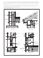
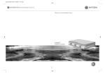
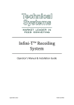
APPROVAL
INSPECTION
TESTING
CERTIFICATION
Beco Products Ltd
5 Atherton Way
Brigg
North Lincolnshire
DN20 8AR
Tel: 01652 653844 Fax: 01724 747579
e-mail: [email protected]
website: www.becowallform.co.uk
TECHNICAL APPROVALS FOR CONSTRUCTION
Agrément Certificate
14/5083
Product Sheet 1
BECO CONCRETE FORMWORK SYSTEMS
BECO WALLFORM INSULATING CONCRETE FORMWORK SYSTEM
This Agrément Certificate Product Sheet (1) relates to the
Beco Wallform Insulating Concrete Formwork System,
comprising expanded polystyrene (EPS) moulded
elements for use in the formation of loadbearing and
non-loadbearing internal, external, separating walls to
provide thermal insulation in residential and commercial
buildings of similar occupancy.
(1) Hereinafter referred to as ‘Certificate’.
CERTIFICATION INCLUDES:
• factors relating to compliance with Building
Regulations where applicable
• factors relating to additional non-regulatory
information where applicable
• independently verified technical specification
• assessment criteria and technical investigations
• design considerations
• installation guidance
• regular surveillance of production
• formal three-yearly review.
KEY FACTORS ASSESSED
Structural performance — the system components have adequate strength to resist the loads associated with
installation loading (see section 6).
Thermal performance — the system contributes to the overall thermal performance of the wall construction (see section 7).
Risk of condensation — walls, openings and junctions with other elements will adequately limit the risk of surface
condensation (see section 8).
Behaviour in relation to fire — the concrete walls formed from the system provide fire resistance when designed in
accordance with BS 8110-2 : 1985 or BS EN 1992-1-2 : 2004 (see section 9).
Sound insulation — separating and internal walls with a minimum concrete core density and detailing stated in this
Certificate will provide sufficient sound resistance (see section 14).
Durability — the system components are durable (see section 16).
The BBA has awarded this Certificate to the company named above for the system described herein. This system
has been assessed by the BBA as being fit for its intended use provided it is installed, used and maintained as set
out in this Certificate.
On behalf of the British Board of Agrément
Date of First issue: 17 February 2014
Brian Chamberlain
Claire Curtis-Thomas
Head of Approvals — Engineering
Chief Executive
The BBA is a UKAS accredited certification body — Number 113. The schedule of the current scope of accreditation for product certification is
available in pdf format via the UKAS link on the BBA website at www.bbacerts.co.uk
Readers are advised to check the validity and latest issue number of this Agrément Certificate by either referring to the BBA website or contacting the BBA direct.
British Board of Agrément
Bucknalls Lane
Watford
Herts WD25 9BA
©2014
Page 1 of 16
tel: 01923 665300
fax: 01923 665301
e-mail: [email protected]
website: www.bbacerts.co.uk
Regulations
In the opinion of the BBA, the Beco Wallform Insulating Concrete Formwork System, if installed, used and maintained
in accordance with the provisions of this Certificate, will meet or contribute to meeting the relevant requirements
of the following Building Regulations (the presence of a UK map indicates that the subject is related to the Building
Regulations in the region or regions of the UK depicted):
The Building Regulations 2010 (England and Wales) (as amended)
Requirement: A1
Requirement: A2
Requirement: A3
Loading
Ground movement
Disproportionate collapse
Comment:
Walls formed from the system will have adequate strength and stiffness to satisfy these Requirements. See
sections 6.1 to 6.4, 6.10 and 6.11 of this Certificate.
Requirement: B3(1)(2)(3)
Internal fire spread (structure)
Comment:
Requirement: C2(a)
Resistance to moisture
Walls formed from the system can meet this Requirement. See sections 9.2 to 9.7 of this Certificate.
Comment:
Walls formed from the system can adequately limit the risk of moisture ingress from the ground. See section
11.1 of this Certificate.
Requirement: C2(c)
Resistance to moisture
Comment:
Walls formed from the system can adequately limit the risk of surface condensation and contribute to
minimising the risk of interstitial condensation. See sections 8.1 and 8.2 of this Certificate.
Requirement: E1
Requirement: E2(a)
Protection against sound from other parts of the building and adjoining buildings
Protection against sound within a dwelling-house etc
Comment:
Walls formed from the system can adequately meet these Requirements. See sections 14.1 to 14.3 of this
Certificate.
Requirement: L1(a)(i)
Conservation of fuel and power
Comment:
Walls formed from the system can contribute to a building meeting its Target Emission Rate. See sections
7.1 to 7.4, 13.1 and 13.2 of this Certificate.
Regulation
7
Materials and workmanship
Comment:
Regulation:
26
CO2 emission rates for new buildings
The system elements are acceptable. See section 16 and the Installation part of this Certificate.
The system can satisfy or contribute to satisfying this Regulation. See sections 7.1 to 7.4, 13.1 and 13.2
of this Certificate.
Comment:
The Building (Scotland) Regulations 2004 (as amended)
Regulation:
8(1)
Regulation:
Standard:
Standard:
9
1.1(a)(b)
1.2
2.2
2.3
3.4
3.15
Comment:
Condensation
Walls formed from the system can adequately limit the risk of surface condensation, with reference to
clauses 3.15.1(1)(2) and 3.15.3(1). Walls can contribute to minimising the risk of interstitial condensation,
with reference to clauses 3.15.1(1), 3.15.4(1) and 3.15.5(1)(2). See sections 8.1 and 8.2 of this Certificate.
Comment:
Standard:
Standard:
Moisture from the ground
Walls formed from the system can satisfy this Standard, with reference to clauses 3.4.1(2) and 3.4.5(1).
See section 11.1 of this Certificate.
Comment:
Standard:
Separation
Structural protection
Walls can satisfy the short, medium or long fire-resistance durations required by this Standard, with
reference to clauses 2.2.1(1), 2.2.2(1)(2), 2.2.3(1)(2), 2.2.5(1)(2) and 2.2.8(1). Junctions between walls can
maintain the required fire-resistance durations with reference to clauses 2.2.7(2) and 2.2.10(1). See
section 9.1 of this Certificate. The expanded polystyrene component of the wall would be classified
as combustible. However, the completed wall can satisfy the required durations of fire-resistance with
reference to clauses 2.2.4(2) and 2.2.7(1). See sections 9.1 to 9.7 of this Certificate.
Comment:
Standard:
Building Standards applicable to construction
Structure
Disproportionate collapse
Walls formed from the system will have adequate strength and stiffness to satisfy this Standard, with
reference to clauses 1.1.1(1)(2) to 1.1.3(1)(2) and, when suitably reinforced, clause 1.2.1(1)(2). See sections
6.2, 6.3, 6.4, 6.10 and 6.11 of this Certificate.
Comment:
Standard:
Standard:
Fitness and durability of materials and workmanship
The system can contribute to a construction meeting this Regulation. See sections 15 and 16 and the
Installation part of this Certificate.
Comment:
5.1
5.2
Noise separation
Noise reduction between rooms
Separating walls formed from the system satisfy these Standards, with reference to clauses 5.1.1(1)(2),
5.1.2(1)(2), 5.1.4(1)(2), 5.1.7(2), 5.1.8(1), 5.2.1(1)(2) and 5.2.2(1)(2). See sections 14.1 and 14.2 of this
Certificate.
Page 2 of 16
Standard:
Standard:
6.1(b)
6.2
The system will enable, or contribute to enabling, a wall to meet these Standards, with reference to clauses
6.1.1(1)(2), 6.1.4(1), 6.1.5(1), 6.2.1(1)(2), 6.2.3(1), 6.2.4(1)(2), 6.2.5(1)(2), 6.2.6(2) and 6.2.7(2). See sections
7.1 to 7.4, 13.1 and 13.3 of this Certificate.
Comment:
Standard:
Carbon dioxide emission
Building insulation envelope
7.1(a)(b)
Statement of sustainability
The system can contribute to meeting the relevant Requirements of Regulation 9, Standards 1 to 6 and
therefore will contribute to a construction meeting a bronze level of sustainability as defined in this Standard.
In addition, the product can contribute to a construction meeting a higher level of sustainability as defined
in this Standard, with reference to clauses 7.1.4(1)(2) [Aspects 1(1)(2) and 2(1)], 7.1.6(1)(2) [Aspects 1(1)(2) and
2(1)] and 7.1.7(1)(2) [Aspect 1(1)(2)]. See sections 7.1 to 7.4 of this Certificate.
Comment:
(1) Technical Handbook (Domestic).
(2) Technical Handbook (Non-Domestic).
The Building Regulations (Northern Ireland) 2012
Regulation:
23(a)(i)()iii)(b)
Fitness of materials and workmanship
Comment:
Regulation:
28(a)(b)
Resistance to moisture and weather
The system is acceptable. See section 16 and the Installation part of this Certificate.
Walls formed from the system can adequately limit the risk of moisture ingress from the ground. See section
11.1 of this Certificate.
Comment:
Regulation:
29
Regulation:
30
Stability
Walls formed from the system will have adequate strength and stiffness to satisfy this Regulation. See
sections 6.2 to 6.4, 6.10 and 6.11 of this Certificate.
Comment:
Regulation:
Condensation
Walls formed from the system can contribute to minimising the risk of interstitial condensation. See sections
8.1 and 8.2 of this Certificate.
Comment:
31
Disproportionate collapse
Walls, when suitably reinforced, will have adequate strength and stiffness to satisfy this Regulation. See
sections 6.2 to 6.4, 6.10 and 6.11 of this Certificate.
Comment:
Regulation:
35
Internal fire spread — Structure
Comment:
Regulation:
Regulation:
39(a)(i)
40(2)
Conservation measures
Target carbon dioxide Emission Rate
Walls formed from the system can satisfy this Regulation. See sections 9.2 to 9.7 of this Certificate.
The system can satisfy or contribute to satisfying this Regulation. See sections 7.1 to 7.4, 13.1 and 13.2
of this Certificate.
Comment:
Regulation:
Regulation:
Regulation:
49
50(a)(b)
51
Comment:
Resistance to the passage of sound
Protection against sound within a dwelling or room for residential purposes
Reverberation in the common internal parts of a buildings containing flats or rooms for residential purposes
The system can satisfy this Regulation. See sections 14.1 and 14.2 of this Certificate.
Construction (Design and Management) Regulations 2007
Construction (Design and Management) Regulations (Northern Ireland) 2007
Information in this Certificate may assist the client, CDM co-ordinator, designer and contractors to address their
obligations under these Regulations.
See sections:
3 Delivery and site handling (3.1 and 3.4) and 17 Installation — General (17.2) of this Certificate.
Additional Information
NHBC Standards 2014
NHBC accepts the use of the Beco Wallform Insulating Concrete Formwork System, provided it is installed, used and
maintained in accordance with this Certificate, in relation to NHBC Standards.
General
Beco Wallform Insulating Concrete Formwork System provides permanent formwork for in-situ dense aggregate
concrete walls (reinforced or plain) and contributes to the thermal insulation of the finished construction. The system
is for use in loadbearing and non-loadbearing internal, external and separating walls in residential and commercial
buildings subject to structural and fire considerations and building use.
The system can also be used below ground, subject to design and supervision by a Chartered Structural Engineer and
adherence to structural design to British or European Standards (see section 6.2) and detailing in accordance with
BS 8102 : 2009. However, below-ground watertight construction and protection against ingress of ground water has
not been assessed and is outside the scope of this Certificate. Use of the system in any structure is subject to design
limitations in accordance with British or European Standards.
Page 3 of 16
Technical Specification
1 Description
1.1 The Beco Wallform Insulating Concrete Formwork System consists of a range of elements (see Figure 1) moulded
from expanded polystyrene (EPS) beads into inner and outer profiled panels connected by integral webs or steel wire
connectors, depending on function. The elements are available in Standard, Acoustic and Firewall grades, and four
system types; 250, 313, 375 and 438 (see Table 1).
Figure 1 Typical standard wall elements (EPS web and steel wire connector)
Table 1 Range of system elements
Element
Overall width
(mm)
Standard Wallblock
A
B
250
55
Width
A
55
Height
(mm)
Core
B
Length
(mm)
250
140
750
312.5
117.5
250
140
750/1125
70
375
180
250
140
750
130
438
243
250
140/200
750
250
55
250
140
1250
50
Firewall block
A
B
55
250
Acoustic block
A
140
312.5
117.5
250
140/200
1250
375
180
250
140/200
1250
438
243
250
140/200
1250
55
250
140
500
117.5
250
140
500
250
312.5
55
250
continued
Page 4 of 16
Table 1 Range of system elements (continued)
Overall width
(mm)
Element
Lintel block
140
A
55
A
140
181
55
Width
&
Height
(mm)
Core
B
length
(mm)
250
55
250
140
Various(1)
375
180
250
140
Various(1)
438
243
250
140
Various(1)
250
55
250
140
1250
375
180
250
140
1250
438
243
250
140
1250
125
69
Floor edge block
196
54
A
140
55
45° Corner Block
250
140/200
A
55
55
250
140
312.5
312.5
117.5
250
140/200
312.5
375
180
250
140/200
312.5
438
243
250
140/200
312.5
250
55
250
140
750
117.5
250
140
Various(1)
375
180
250
140
Various(1)
438
243
250
140
Various(1)
250
–
250
140
Various(1)
375
–
250
140
Various(1)
438
–
250
140
Various(1)
140
–
85/105
–
–
250
Curved/Curved Transition Wall Block
140
312.5
55
A
250
End block
140
A
55
250
End set
140
105
85
140
continued
Page 5 of 16
Table 1 Range of system elements (continued)
Element
Overall width
(mm)
Width
A
Height
(mm)
Core
B
Length
(mm)
55
–
62.5
–
750
120
–
62.5
–
750
183
–
62.5
–
750
Height adjuster
55
62.5
End piece
77.5
140
B
250
–
250
–
–
250
–
202.5
–
250
–
265
–
250
–
Fire stop end piece
250
Corbel block
250
(1) In increments of 62.5 mm.
1.2 The elements are provided with castellated joints along the top and bottom edges and interlocking joints at
vertical edges. All element faces have grooves 2.5 mm deep and 17.5 mm wide at 62.5 mm centres to provide a key
for the application of plaster or render. Each element interlocks and builds, horizontally and vertically, into a tight, rigid
formwork when connected together. Once connected together, the formwork enables a series of connecting concrete
columns or a continuous concrete core 140 mm or 200 mm wide to be formed by pouring concrete into the formwork.
1.3 The range of elements also include; curved blocks, lintel block, floor edge block, height adjuster, end set and end
piece. The Certificate holder scan be contacted for further details.
1.4 The expanded polystyrene (EPS) used in the elements has the properties given in Table 2.
Table 2 EPS properties
Property
Test method
Estimated thermal conductivity lambda
90/90
value (W·m ·K )
–1
–1
Compressive strength at 10% deformation (kN·m–2)
Value to BS EN 13163: 2008
BS EN 12667: 2001
0.038
BS EN 826: 1996
150
Bending strength (kN·m–3)
BS EN 12089 : 1997
200
Density (kg·m–3)
BS EN 602 : 2004
28
1.5 The concrete infill is sourced from QSRMC(1)-registered or a BSI-Kitemarked batching plant or supplier and must be
of the specification defined in Table 3. All concrete design for above and below ground construction must be carried
out to relevant British or European Standards. The Certificate holder recommends a use of pumpable grade concrete.
(1) Quality Scheme for Ready Mixed Concrete.
Table 3 Recommended concrete specification and characteristics
Characteristic (units)
Specification
unreinforced
C25/30
reinforced
C35/45
Minimum density (kg·m–3)
2200
Minimum mass (kg·m )
415
–2
Slump class
S3
Target slump (mm)
100-150
(1)
Maximum aggregate size (mm):
Pumped
Free flow
10
<20
Minimum cement content (kg·m–3)
300
Water : cement ratio
defined by structural engineer
(1) In accordance with BS EN 206-1 : 2000 and BS EN 12350-2 : 2000.
1.6 Where admixtures are used to assist placement they should comply with BS EN 934-2 : 2001 or BS EN 480-1 :
2006.
Page 6 of 16
1.7 Other components and finishes specified for use with the system but not assessed or covered by this Certificate are:
• wall foundation
• steel reinforcement — where required, should comply with BS 4449 : 2005 and sourced from a CARES (UK
Certification Authority for Reinforcing Steels) registered supplier
• external masonry — may be of brickwork, or stonework fixed in accordance with the provisions of BS EN 1996-1-2 :
2005 or the appropriate part of BS 8298 : 2010 respectively
• external render — in accordance with BS EN 13914-1 : 2005 and suitable for use with the system
• acrylic render — suitable acrylic render products in accordance with BS EN 13914-1 : 2005 for use with the
system
• brick slip systems — third-party certificated systems (the Certificate holder’s advice should be sought)
• brickwork/stonework ties — to BS EN 845-1 : 2003
• fire barriers
• propping/support system — as recommended by the Certificate holder
• basement waterproofing membrane
• plasterboard internal linings — to BS EN 520 : 2004 and BS 8212 : 1995.
2 Manufacture
2.1 The formwork elements are manufactured from expanded polystyrene (EPS).
2.2 As part of the assessment and ongoing surveillance of product quality, the BBA has:
• agreed with the manufacturer the quality control procedures and product testing to be undertaken
• assessed and agreed the quality control operated over batches of incoming materials
• monitored the production process and verified that it is in accordance with the documented process
• evaluated the process for management of nonconformities
• checked that equipment has been properly tested and calibrated
• undertaken to carry out the above measures on a regular basis through a surveillance process, to verify that the
specifications and quality control operated by the manufacturer are being maintained.
3 Delivery and site handling
3.1 Good site practice should be observed to prevent damage to the formwork elements.
3.2 The system elements are supplied to site interlocked with corner protection pieces in taped, or shrink wrapped
packs. All packaged elements are clearly labelled with product type and code number, allowing full traceability of
supply. The wrapping should not be opened until the contents are required.
3.3 The formwork elements must be stored in their packaging on firm, level and dry ground. If stored outside packs
must be further protected from the weather using opaque plastic sheeting or tarpaulin.
3.4 Care must be taken when handling the EPS elements to avoid damage and contact with solvents or materials
containing volatile organic components such as newly treated timber. The elements must not be exposed to open flame
or other ignition sources.
Assessment and Technical Investigations
The following is a summary of the assessment and technical investigations carried out on the Beco Wallform Insulating
Concrete Formwork System.
Design Considerations
4 Use
4.1 The Beco Wallform Insulating Concrete Formwork System is for use as permanent insulated formwork in
loadbearing and non-loadbearing reinforced and unreinforced concrete external, internal and separating walls in
domestic and commercial buildings, subject to design limitations regarding height, load and fire risk. Use in any
structures is subject to design limitations in accordance with British or European Standards.
4.2 The system provides permanent formwork for in-situ concrete walls and contributes to the thermal insulation of the
finished construction.
4.3 The system has not been assessed for use below ground, such as basement construction, where a watertight
construction and resistance to hydrostatic pressure from ground water or other liquids is required. Use in this situation is
therefore outside the scope of this Certificate.
4.4 The foundations are outside the scope of this Certificate but must be adequate to support the intended loads.
4.5 The system is for use with the internal and external finishes to the specification given in section 1.7 of this Certificate.
Page 7 of 16
5 Practicability of installation
The system must only be installed by installers who have been trained and approved by the Certificate holder (see
sections 17 and 18).
6 Structural performance
General
6.1 The system is satisfactory for use in loadbearing and non-loadbearing walls as permanent formwork for
in-situ dense aggregate concrete.
6.2 Structures subject to the national Building Regulations incorporating the system should be designed to the
relevant sections of BS 8007 : 1987, BS 8102 : 2009, BS 8110-1 : 1997 or BS EN 1991-1-4 : 2005,
BS EN 1992-1-1 : 2004 and BS EN 1992-1-2 : 2004 and certified by a suitably qualified and experienced
individual.
6.3 Other buildings not subject to any of the Regulations defined in section 6.2 should also be built in accordance
with these same Standards.
6.4 The concrete is not easily examined after casting, therefore, as specified in BS 8110-1 : 1997, Section 2, or
BS EN 1992-1-1 : 2004, Sections 4 and 8, care must be taken to ensure full compaction is achieved. If required,
compaction may be checked by removal of a small section of the EPS element to allow observation and then securely
replaced. Particular attention should be given to compaction of concrete in basement walls and areas adjacent to
formed openings.
6.5 Storey-height walls using the system are normally constructed in one continuous lift (see section 17.4). Particular
care is necessary to maintain alignment during concrete filling, and checking between lifts. Propping systems (see
section 6.12) used in conjunction with the formwork must be checked prior to and during the concrete pour to ensure
stability and alignment is maintained.
6.6 With respect of concrete placement and especially regards any use of poker vibration for compaction of
wet concrete (see also section 17.5) the Beco Wallform Insulating Concrete Formwork Technical Manual must be
consulted.
6.7 When the formwork is used to construct a watertight basement (not covered by this Certificate), an effective
waterproofing should be employed, ensuring correct detailing and jointing methodology to the Certificate holder’s
instructions and the requirements of BS 8102 : 2009 for Types A and C basement construction.
6.8 Generally, facing brickwork or stonework should be attached using suitable wall ties that are fixed through the
formwork and into the concrete core with suitable fixings (see section 1.7) to the depth recommended by the wall tie
manufacturer.
6.9 Heavy attachments or finishes, fixed either internally or externally, must be attached via support systems designed
to take account of the applied load using suitable fixings or plates fixed or cast into the concrete core. The EPS must
not be used to support any internal or external loads.
Strength and stability
6.10 Walls constructed using the formwork may be treated as conventional unreinforced (plain) concrete or
reinforced concrete walls. Particular attention should be made to the type of concrete mix used (see Table 3) to
ensure segregation does not occur and the wet concrete is allowed to flow freely around formed openings and
through congested areas of reinforcement.
6.11 The nominal concrete cover to reinforcement should be that appropriate to exposure classes X0 and XC1
described in BS 8500-1 : 2006, Table A.1 and BS EN 206-1 : 2000, Table 1.
6.12 To achieve a structurally stable formwork during the construction process, the formwork must be braced
sufficiently to resist the loads imparted on the system by the wet concrete and other construction loads. A typical system
of temporary bracing should be designed to give lateral support during the pouring of the concrete and curing stage.
The Certificate holder recommends that propping is provided at maximum 1.5 metre centres, or less when openings
are formed in the wall. All soffits to openings should be fully supported until the concrete has attained the minimum
required strength.
Page 8 of 16
7 Thermal performance
7.1 The thermal performance of each building incorporating the forms must be evaluated in accordance with
the relevant national Building Regulations, and is the responsibility of the overall designer of the building.
7.2 Calculations of the thermal transmittance (U value) of a specific wall construction should be carried out in
accordance with BS EN ISO 6946 : 2007 and BRE report 443 : 2006 using an estimated lambda 90/90 value
thermal conductivity of 0.038 W·m–1·K–1.
7.3 As an example, using the Standard Wallform 313 (117.5 mm outer face and 55 mm inner face) with 10 mm
directly applied external render finish and 12.5 mm directly applied plaster internal finish, can achieve a U value of
0.206 W·m–2·K–1. Other wall constructions that require internal and external finishes to be fixed into rails or concrete
core, will affect the thermal transmittance, as will chasing into the EPS for services. Therefore, for other constructions,
specific thermal calculations will need to be carried out in accordance with BS EN ISO 6946 : 2007 to determine
U values.
7.4 Junctions with other elements should be designed to limit heat loss. Detailed guidance for junctions and on limiting
heat loss by air infiltration can be found in:
England and Wales — Approved Documents to Part L and, for new thermal elements to existing buildings, Accredited
Construction Details (version 1.0) (for new-build, see also SAP 2009, Appendix K, and the iSBEM User Manual)
Scotland — Accredited Construction Details(1)
Northern Ireland — Accredited Construction Details (version 1.0).
(1) Flexible approaches on existing buildings are given in the Technical Handbooks.
8 Risk of condensation
Surface condensation
8.1 External walls will adequately limit the risk of surface condensation. Openings in walls and junctions with
other elements, designed in accordance with the relevant guidance given in section 11, will also be acceptable.
Interstitial condensation
8.2 Subject to the construction used and amount of vapour being produced, the risk of interstitial condensation
will be minimal. Any vapour build-up will be low and will dissipate during the summer months. Therefore, a vapour
check is not required. For the purposes of calculating condensation risk a water vapour resistance factor (µ) of 60, in
accordance with BS EN 12524 : 2000, may be taken for the EPS.
9 Behaviour in relation to fire
9.1 The Firewall system elements must be used in the construction of separating walls. The provisions set out in
sections 9.7 and 9.8 should be taken into account when using the Standard system elements (ie with EPS webs).
9.2 The formwork elements are combustible. For buildings in Scotland, completed walls with appropriate
finishes can satisfy the required durations of fire resistance and, therefore, may be used in separating
walls. Where external walls are one metre or less from a relevant boundary, the construction should
comply with the relevant exceptions on the use of combustible materials permitted by the guidance supporting the
Building Regulations in Scotland.
9.3 EPS is combustible so the risk of fire spread over the internal wall surface will depend on the finishes that
are used and the relevant requirements of the national Building Regulations should be observed.
9.4 Where the system is used as part of a cavity wall construction; to limit the risk of fire spread between floors in
buildings subject to the Building Regulations, fire barriers should be installed at each floor level above the first floor
(ie starting at the second storey). Fire barriers should completely seal the cavity and be chased fully into the outer
formwork.
9.5 Care should be taken to ensure that all detailing at junctions, including external wall/separating wall junctions
and wall/floor junctions, adequately maintains the required periods of fire resistance. Any cavities formed in the
completed walls or service entry points must be appropriately fire stopped and detailing around any openings provide
sufficient protection to the formwork. The formwork on the interior face must be discontinuous across wall/floor
junctions.
9.6 Reinforced concrete walls constructed from the Firewall system elements can be assessed in accordance with
BS 8110-2 : 1985, Table 4.6. Fire resistance values for various reinforced concrete wall thicknesses formed using
the elements are given in this table. Fire resistance values achievable using the systems are given in Tables 4 and 5.
Alternatively, if reinforced concrete walls are designed in accordance with BS EN 1992-1-1 : 2004, fire resistance
values for various concrete wall thicknesses set out in BS EN 1992-1-2 : 2004, Table 5.4, can be used, subject to
cover and design load considerations. The tabulated values do not take account of any additional protection provided
by the internal and external finishes.
Page 9 of 16
Table 4 Fire resistant values (minutes) for minimum concrete core thickness for walls (Firewall elements only) with
vertical reinforcement (BS 8110-2 only) (1)
Reinforcement and concrete specification
Concrete thickness (mm)(2)
30
Walls with less than 4% reinforcement made from dense aggregate
60
90
180
240
–
–
200
–
–
Walls with 0.4% to 1% reinforcement made from dense aggregate with 25 mm cover to reinforcement
140
140
140
200
–
Walls with over 1% reinforcement made from dense aggregate with 25 mm cover to reinforcement
140
140
140
200
200
(1) Concrete walls constructed from the formwork system have been assessed in accordance with BS 8110-2 : 1985, Table 4.6 (note: actual element core
widths stated in Table 4).
(2) Excluding any combustible finish for a fire resistance (loadbearing capacity, integrity and insulation).
Table 5 Minimum concrete core thickness for loadbearing reinforced concrete walls(Firewall elements only) as
per BS EN 1992-1-2 : 2004, Table 5.4
Standard fire resistance
Minimum dimensions (mm)
Wall thickness/axis distance(1) for:
µfi(2) = 0.35
µfi(2) = 0.7
wall exposed on one side
wall exposed on two sides
wall exposed on one side
REI 30
100/10
120/10
120/10
REI 60
110/10(3)
REI 90
120/20
(3)
(3)
wall exposed on two sides
(3)
120/10(3)
120/10(3)
130/10(3)
140/10(3)
140/10
140/25
(3)
(3)
(3)
170/25
(1) Centre of reinforcement to nearest exposed surface.
(2) The definition of µfi is given in BS EN 1992-1-1 : 2004, Section 5.3.2(3).
(3) Normally, the cover specified in BS EN 1992-1-1: 2004 will control this distance.
9.7 Reinforced concrete walls constructed from the Standard system elements (ie with EPS webs, for use in other
than separating walls), should be assessed for fire resistance in accordance with BS 8110-2 : 1985, section 4 or
BS EN 1992-1-2 : 2004, section 5.3.
9.8 For unreinforced walls constructed from the Firewall system elements, acting as fire walls, the minimum thickness
requirements set out in BS EN 1992-1-2 : 2004, clause 5.4.2, must be taken into account.
10 Weathertightness
Resistance to rain ingress is provided by the external finishes and has not been assessed by the BBA. Care should be
taken to ensure the design and construction using the system complies with the relevant good practice described in the
applicable codes and the Certificate holder’s Installation procedures.
11 Damp-proofing and waterproofing
11.1 The formwork elements will not transmit moisture by capillary action. The concrete wall formed with the
system should be constructed using the specified concrete recommended by the Certificate holder (see sections
1.5, 6.10 and 6.11).
11.2 Use of the system below ground to resist the effects of hydrostatic head or ground water ingress has not been
assessed and is not covered by this Certificate. The recommendations given in BS 8102 : 2009 should be adopted
in respect of the watertightness of the whole structure (see also section 4.3). The advice of the Certificate holder should
be sought on particular applications. Where a type A or C basement construction is adopted, suitable collector drain
and backfilling medium should be provided to eliminate the build up of hydrostatic head behind the wall, where
required. The Certificate holder should be consulted for advice on suitable waterproofing materials and methods of
waterproofing.
11.3 Window and door openings and penetrations of the concrete, such as pipe entries or formwork ties, must also
be securely sealed to maintain watertightness. The advice of the Certificate holder should be sought on suitable details.
12 Proximity of flues and appliances
When installing the product in close proximity to certain flue pipes and/or heat-producing appliances, the following
provisions to the national Building Regulations are acceptable:
England and Wales — Approved Document J3
Scotland — Mandatory Standards 3.18, clause 3.18.5(1), and 3.19, clause 3.19.4(1)
Northern Ireland — Technical Booklet L.
(1) Technical Handbook (Domestic).
Page 10 of 16
13 Airtightness
13.1 Buildings can achieve adequate resistance to heat loss by air infiltration provided there is effective sealing
around junctions between units during site assembly. Care should be taken to ensure that junctions with other
elements and openings comply with the relevant guidance for airtightness as given in the relevant documents
referred to in section 7.4.
13.2 In England, Wales and Northern Ireland, completed buildings are subject to pre-completion testing for
airtightness in accordance with the requirements of:
England and Wales — Approved Document L1A (section 43) L2A (section 20B)
Northern Ireland — Technical Booklets F1 (Sections 2.59 to 2.69) and F2 (Sections 2.72 to 2.77).
13.3 In Scotland, completed dwellings are subject to testing air permeability in accordance with the requirements
of Mandatory Standard 6.2 (clause 6.2.5). Alternatively, where a default design value of 15 m3·m–2·h–1 at
50 Pa is stated in demonstrating compliance under Mandatory Standard 6.1, testing is not required.
14 Sound insulation
14.1 In England and Wales, separating walls are subject to pre-completion testing in accordance with
Approved Document E, Section 1. A similar approach is described in the Scottish Building Standards, section
5.1.2(1) and the Building Regulations (Northern Ireland), Document G.
14.2 Internal walls and walls flanking separating walls in new dwellings and rooms for residential purposes should
have a minimum mass per unit area, excluding finishes, in excess of 120 kg·m–2.
14.3 Separating walls with a concrete core density greater than 2200 kg·m–3 and thickness of 200 mm, will
achieve a minimum mass per unit area for the core of 415 kg·m–2 and can contribute to providing the
requirements of Approved Document E, Section 2.
15 Maintenance and repair
Minor repairs to the formwork can be carried out prior to concrete pouring using expanded foam, to reduce
leakage of wet concrete and maintain the thermal integrity of the EPS.
16 Durability
Concrete walls constructed with the system will have a service life of not less than 60 years provided they are
designed in accordance with section 6. The formwork system elements will have a similar service life provided it
is protected from damage by the external and internal finishes of the wall construction (constituting a ’mild’
exposure environment) and these are adequately maintained.
Installation
17 General
17.1 Installation of the Beco Wallform Insulating Concrete Formwork System is carried out in accordance with the
Certificate holder’s installation instructions, by trained, approved or supervised operatives and the requirements of
BS 5975 : 2008 and BS 8000-2.1 : 1990. Continuous supervision during placing and compacting of the concrete
must be provided. Where required, the formwork elements can be cut using conventional woodworking tools.
17.2 Attention is drawn to the need for accurate levelling of the foundation and initial setting out of adjustments to be made.
17.3 In general, concrete should be placed by line pump and nozzle although small quantities of concrete (e.g. to
window sills), can be placed by hand. As an alternative, crane and skip can be employed.
17.4 Concrete must be compacted in accordance with the requirements of BS EN 1992-1-1 ; 2004 or BS 8110-1 :
1997. Concrete placement must not exceed a flow rate of 12 m3·h–1 in passes not exceeding 0.5 metre in height for
reinforced concrete and 0.9 metre in height for unreinforced walls. The total daily pour height must not exceed 3 metres.
17.5 For unreinforced walls, compaction of the concrete by hand tamping or rodding is adequate. For reinforced
walls mechanical compaction should be employed, using external pad or poker vibrators not exceeding 25 mm
diameter as the formwork elements are easily damaged.
17.6 Where required, additional reinforcement can be placed within the system and quantities are dependent on
design and detail requirements (see section 6). Horizontal reinforcement can be placed in different locations across the
concrete fill void using the EPS webs or wire ties as temporary support. Vertical reinforcement can be placed against
the horizontal reinforcement and secured using standard fixing methods. Bar lapping lengths in accordance with
BS EN 1992-1-1 : 2004 or BS 8110-1 : 1997 should be adopted. All reinforcement should be accurately positioned
to ensure that the minimum required cover to the concrete is provided. Starter or dowel bars may be recommended
depending on reinforcement requirements or engineer’s specification. Ties should not be cut or modified when locating
reinforcement. The use of steel fibres as an alternative to standard reinforcement (bar or mesh) has not been assessed
by the BBA. If used it must be subject to approval of the person responsible in the building design.
Page 11 of 16
17.7 The concrete can be placed in freezing conditions as it will be thermally protected by insulation provided by the
formwork, although the temperature of the concrete being placed must be between 5°C and 30°C. In air temperatures
below 5°C or temperatures above 25°C the top of the formwork should be protected to aid curing after completion of
concreting.
17.8 Suitably durable and mechanically adequate fixings, reinforcing starter bars or support brackets must be used
for all structural elements, eg floors and roofs (see Figure 2), and must be post-drilled or cast into the concrete core. The
EPS elements must not be used as a structural medium.
Figure 2 Typical installation
floor screed
insulation
waterproofing
additive mixed
with concrete
floor level
ground level
external render
dpm
ceiling joist and
ceiling finish
concrete slab
wallplate fixed
to Wallform
structure
insulation
Wallform
foundation detail
Wallform
lintel block
wall and roof detail
lintel reinforcing
Wallform
lintel block
lintel reinforcing
sealant
sealant
gap filling foam
cap filling foam
sealant
plug and screw
fixing through
jambs of frame
direct into concrete
galvanised metal
straps, screwed
to frame, plugged
and screwed to
concrete core
sealant
sealant
expanding
foam
expanding foam
Wallblock
insert
Wallblock
insert
window openings ⫺ cill
door/window detail
Page 12 of 16
Figure 2 Typical installation (continued)
Wallform
height adjuster
standard Wallform
floor level
floor level
timber joist
pre-cast beam and
block floor units
concrete floor
timber floor
18 Preparation
18.1 The preparation, installation and temporary support of the formwork system must be in accordance with the
Certificate holder’s installation instructions.
18.2 The foundation must be level, smooth finished, cleaned off and within a tolerance of ± 10 mm in any direction.
Any out-of-tolerances must be made good prior to placement of formwork.
18.3 When stepped foundations are required, 250 mm steps should be provided wherever possible to minimise
cutting of forms and wastage.
19 Procedure
Wall assembly
19.1 Prior to the damp proof course being laid, a line of the wall to be built is first checked.
19.2 Starting at the corners and working into the centre point of each wall, the formwork elements are pushed firmly
together using a stretcher bond format.
19.3 Depending on the footing detail required, the following and subsequent courses are then built up (ensuring that
vertical joints do not coincide). End pieces are inserted into any opening sides as erection of the formwork proceeds as
should any reinforcement required for structural design purposes.
19.4 Where the specified storey height is not a multiple of 250 mm, height adjusters may increase height in
increments of 62.5 mm, or alternatively, the formwork can be cut to suit.
19.5 Window and door openings (see Figure 2) are formed and trimmed during construction of the formwork and
framed using specific formwork lintel elements and end pieces. Openings should be made slightly undersize, then
trimmed after the concrete has been cured to obtain an accurate opening size and avoid the need for supplementary
packing. All openings and lintels formed as part of the construction works must be adequately braced and supported
until the concrete has attained its minimum design strength.
19.6 It is essential that effective bracing and propping of walls takes place during construction to ensure stability, level,
straightness and plumb of walls. The Certificate holder can advise on the provision of propping systems.
19.7 As a minimum, the full height of the assembled formwork must be supported at corners and along the wall
lengths with bracings at a maximum 1.5 metre centres. As the rigidity of the formwork is reduced by openings,
additional bracing and propping must be introduced to maintain stability during concrete pouring.
Concrete placement
19.8 Prior to concrete pouring, a check is carried out on the system to ensure conformity to design and layout, correct
alignment and plumb, and that bracings and props are secured. Reinforcement should be checked for correct cover
distance and rigidity. Where reinforcement is only provided above openings, the individual bars should extend at least
500 mm beyond the opening span.
Page 13 of 16
19.9 For concrete pumping, line diameter at point of delivery should be 100 mm using a flexible end hose and
concreting nozzle. The concrete pumping rate should be such that excessive pressure is not allowed to occur, both for
the safety of the site operative and to avoid damage to the formwork. The stream of concrete should be aimed directly
into the void and away from corners. The concrete pour height should be restricted to 500 mm for reinforced concrete
and 900 mm for unreinforced concrete.
19.10 The formwork should be checked for alignment and plumb before proceeding with the next pass; this will also
allow the first pour to stiffen. The next pass proceeds in the same manner until the first storey-height has been reached.
At window and door openings, concrete is poured either side of each opening up to sill level and the concrete
allowed to stiffen before the next pour is commenced.
19.11 When forming horizontal construction joints between concrete pours a gap of 100 mm should be left below
top of formwork lifts.
Heavy wall loads
19.12 Heavy wall loads (such as structural members) should be supported by the concrete core and not the formwork
elements. This can be achieved by the use of timber blocks screwed or bolted into the concrete core, or cast-in anchor
bolts and metal plates.
19.13 Consideration should be given at the design stage to the positioning of damp-proof courses and gas
membranes, wall fixings, service pipes and joists, relative to the position of connecting assemblies. They can be
incorporated by following the manufacturer’s details. Care must be taken not to damage the elements and cold
bridging effects must be considered.
20 Finishing
Backfilling
20.1 Backfilling around bottom layers of formwork to the ground floor or basement walls must not take place until the
concrete structure has reached sufficient design strength (as directed by the person responsible for the structural design).
Electrical and plumbing
20.2 Electrical and plumbing services can be fixed within the formwork by cutting chases into the EPS using a router,
hot wire cutter or plasterboard knife. All electrical services should be ducted. Any services introduced should conform
to Building Regulation and Health and Safety requirements. Further details on fixing methods can be obtained from the
Certificate holder.
Wall penetrations
20.3 Sleeves for ducts or service penetrations may be positioned within the formwork prior to concrete pouring.
Service entry points to basement walls should be avoided. All service entry point should be sealed to prevent ingress of
water, dampness or vermin.
Internal wall finishes
20.4 A range of internal finishes can be applied or fixed directly to the system subject to fire restrictions. Where
conventional dry lining systems, based on gypsum plasterboard, are used they should be screw-fixed into the
concrete core.
External wall finishes
20.5 External cladding must be supported by means of a system compatible with the specified cladding and the
Wallform construction. Masonry systems may be supported by wall ties cast into the concrete core of the wall; curtain
wall, timber or panel claddings may be supported by batten and rail systems pinned back to the concrete core. Render
Systems (described in section 1.7) can be applied directly to the EPS surface in conjunction with metal or plastic lathing
and suitable fixings. Further details can be obtained from the Certificate holder.
Technical Investigations
21 Tests
Site observations were carried out in broad accordance with the requirements of ETAG 009 : 2002 as part of normal
construction under site conditions. Hydrostatic pressures in excess of the restrictions imposed in this Certificate (see
section 6.5) resisted the wet concrete: indicating an adequate factor of safety when installed in accordance with this
Certificate. The efficiency of filling using a line pump and the overall stability of formwork due to head of wet concrete
was also noted.
22 Investigations
22.1 A site visit was carried out to witness the installation process including construction of formwork, placement of
reinforcement and pouring of concrete and overall performance of the formwork.
22.2 An assessment was made on technical data relating to:
• thermal performance.
• Acoustic performance
• Fire performance.
Page 14 of 16
Bibliography
BRE report 443 : 2006 Conventions for U-value calculations
BS 4449 : 2005 Steel for the reinforcement of concrete — Weldable reinforcing steel — Bar coil and decoiled
product — Specification
BS 5975 : 2008 +A1:2011 Code of practice for temporary works procedures and the permissible stress design of
falsework
BS 8000-2.1 : 1990 Workmanship on building sites — Code of practice for concrete work — Mixing and
transporting concrete
BS 8007 : 1987 Code of practice for design of concrete structures for retaining aqueous liquids
BS 8102 : 2009 Code of practice for protection of structures against water from the ground
BS 8110-1 : 1997 Structural use of concrete — Code of practice for design and construction
BS 8110-2 : 1985 Structural use of concrete — Code of practice for special circumstances
BS 8212 : 1995 Code of practice for dry lining and partitioning using gypsum plasterboard
BS 8298-1 : 2010 Code of practice for the design and installation of natural stone cladding and lining. General
BS 8298-2 : 2010 Code of practice for the design and installation of natural stone cladding and lining. Traditional
handset external cladding
BS 8298-3 : 2010 Code of practice for the design and installation of natural stone cladding and lining — Stonefaced pre-cast concrete cladding systems
BS 8500-1 : 2006 Concrete — Complementary British Standard to BS EN 206-1. Method of specifying and
guidance for the specifier
BS EN 206-1 : 2000 Concrete — Specification, performance, production and conformity
BS EN 480-1 : 2006 Admixtures for concrete, mortar and grout — Test methods — Reference concrete and reference
mortar for testing
BS EN 520 : 2004 Gypsum plasterboards — Definitions, requirements and test methods
BS EN 602 : 2004 Aluminium and aluminium alloys — Wrought products — Chemical composition of semi-finished
products used for the fabrication of articles for use in contact with foodstuff
BS EN 826 : 1996 Thermal insulating products for building applications — Determination of compression behaviour
BS EN 845-1 : 2003 Specification for ancillary components for masonry — Ties, tension straps, hangers and brackets
BS EN 934-2 : 2001 Admixtures for concrete, mortar and grout — Concrete admixtures — Definitions and
requirements, conformity, marking and labelling
BS EN 1991-1-4 : 2004 Eurocode 1 : Actions on structures — General actions — Wind actions
BS EN 1992-1-1 : 2004 Eurocode 2 : Design of concrete structures — General rules and rules for buildings
BS EN 1992-1-2 : 2004 Eurocode 2 : Design of concrete structures — General rules and rules for buildings. General
rules. Structural fire design
BS EN 1996-1-2 : 2005 Eurocode 6 : Design of masonry structures — General rules — Structural fire design
BS EN 12089 : 1997 Thermal insulating products for building applications — Determination of bending behaviour
BS EN 12350-2 : 2000 Testing fresh concrete — Slump test
BS EN 12524 : 2000 Building materials and products — Hygrothermal properties — Tabulated design values
BS EN 12667 : 2001 Thermal performance of building materials and products — Determination of thermal resistance
by means of guarded hot plate and heat flow meter methods — Products of high and medium thermal resistance
BS EN 13914-1 : 2005 Design, preparation and application of external rendering and internal plastering — External
rendering
BS EN ISO 6946 : 1997 Building components and building elements — Thermal resistance and thermal transmittance
— Calculation method
ETAG 009 : 2002 Non Loadbearing permanent shuttering kit/systems based on hollow blocks or panels of insulating
materials and sometimes concrete
Page 15 of 16
Conditions of Certification
23 Conditions
23.1 This Certificate:
• relates only to the product/system that is named and described on the front page
• is issued only to the company, firm, organisation or person named on the front page — no other company, firm,
organisation or person may hold or claim that this Certificate has been issued to them
• is valid only within the UK
• has to be read, considered and used as a whole document — it may be misleading and will be incomplete to be
selective
• is copyright of the BBA
• is subject to English Law.
23.2 Publications, documents, specifications, legislation, regulations, standards and the like referenced in this Certificate
are those that were current and/or deemed relevant by the BBA at the date of issue or reissue of this Certificate.
23.3 This Certificate will remain valid for an unlimited period provided that the product/system and its manufacture
and/or fabrication, including all related and relevant parts and processes thereof:
• are maintained at or above the levels which have been assessed and found to be satisfactory by the BBA
• continue to be checked as and when deemed appropriate by the BBA under arrangements that it will determine
• are reviewed by the BBA as and when it considers appropriate.
23.4 The BBA has used due skill, care and diligence in preparing this Certificate, but no warranty is provided.
23.5 In issuing this Certificate, the BBA is not responsible and is excluded from any liability to any company, firm,
organisation or person, for any matters arising directly or indirectly from:
• the presence or absence of any patent, intellectual property or similar rights subsisting in the product/system or any
other product/system
• the right of the Certificate holder to manufacture, supply, install, maintain or market the product/system
• actual installations of the product/system, including their nature, design, methods, performance, workmanship and
maintenance
• any works and constructions in which the product/system is installed, including their nature, design, methods,
performance, workmanship and maintenance
• any loss or damage, including personal injury, howsoever caused by the product/system, including its manufacture,
supply, installation, use, maintenance and removal
• any claims by the manufacturer relating to CE marking.
23.6 Any information relating to the manufacture, supply, installation, use, maintenance and removal of this product/
system which is contained or referred to in this Certificate is the minimum required to be met when the product/system
is manufactured, supplied, installed, used, maintained and removed. It does not purport in any way to restate the
requirements of the Health and Safety at Work etc. Act 1974, or of any other statutory, common law or other duty
which may exist at the date of issue or reissue of this Certificate; nor is conformity with such information to be taken as
satisfying the requirements of the 1974 Act or of any statutory, common law or other duty of care.
British Board of Agrément
Bucknalls Lane
Watford
Herts WD25 9BA
©2014
Page 16 of 16
tel: 01923 665300
fax: 01923 665301
e-mail: [email protected]
website: www.bbacerts.co.uk