1
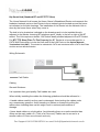
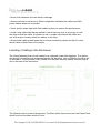
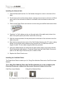
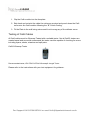
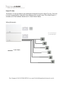
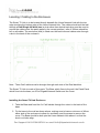
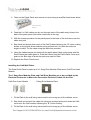
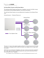
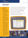
Installation Manual
For Support Call 01704 807114 or email [email protected]
Hip Smart Hub (Standard BT and BT FTTP Sites)
The Home Network Hub houses the Home Owner’s Broadband Router and connects the
hardwired network ports on that Router to three network points located around the home
as indicated on the plot drawings. The installation of the Router into the Network Hub is
done by the home owner when they move in.
The hub is to be located as indicated on the drawings and is to be installed directly
adjacent to the Master Incoming BT telephone point, ideally to the left or right of the BT
socket. The Hub requires a double 13A Socket ideally situated adjacent to the BT Socket.
For BT FTTP Sites (Fibre To The Property) the BT Socket is to be exchanged for a
CAT6 Wall Plate which is to be fed from one of the LAN Ports on the Optical Network
Termination Unit (ONT). This should be cabled with CAT6 and terminated with a CAT6 Wall Plate
at either end as described below.
Wiring Schematic
Cat6 Cable
Cabling
General Guidance
It is important that good quality Cat6 cables are used.
When initially installing the cables the following guidelines should be adhered to :• Handle cables carefully as they can be damaged. Avoid putting the cables under
any unnecessary pressure. Avoid standing on cables or excessively pulling the
cables when installing them as this might result in reduced performance or
damage.
• Never bend cables on a tight radius. Avoid bending them on a radius smaller than
40mm on the main cable run. (Think of a Coke can). Cables can be curved to a
smaller radius of 15mm once at each end only.
For Support Call 01704 807114 or email [email protected]
• Never kink cables as this can result in damage.
• Always maintain a minimum of 300mm separation between the cables and 240v
power cables when run in parallel.
• Never pull tie wraps tight with Cat6 cables as this can reduce the performance.
• Avoid using cable clips that are nailed in with a hammer as it is very easy to miss
the clips and hit the cable. It is better to nail in a cable clip without the cable and
use a tie wrap to loosely attach the cables to the clips.
• Always label cable at both ends with a unique numbering system so that it is clear
which cable is which later in the project.
Locating / Cabling to the Enclosure
The Home Network Hub is to be located in a cupboard as per site drawings. The cables
should exit the wall through a standard double UK back box, tails of 300mm should be left
on all cables. The enclosure (hub) is fitted over the back box and cables enter through a
slot in the back of the enclosure.
The Network Hub is made of three parts. The Base which fixes to the wall, the Patch Panel
which fixes into the base and the Cover.
For Support Call 01704 807114 or email [email protected]
Installing the Network Hub
1. Take the Base and feed the 3 x Cat6 cables through the cutout in the back of the
base.
2. Fix the base to the wall as shown above, making sure to leave a minimum of 25mm
either side of the enclosure to allow for ventilation and for access to remove the
cover.
3. Take out the Patch Panel and remove its cover using a small flat head screw driver.
4. Feed the 3 x Cat6 cables one by one through each of the cable entry holes in the
back of the patch panel (the holes need to be at the top).
5. With the screws provided, fix the patch panel to the back of the enclosure over the
cable entry slot.
6. Strip back and punch down each of the Cat6 Cables following the “B” colour coding
shown on the punch down modules using a Krone tool. Un-twist the minimum
length of cable. Tie the cable using the cable ties provided.
7. Using the Labels/inserts provided with the patch panel, label up the ports with the
Room Name that cable goes to. Push the Labels onto the Patch Panel Cover and
push on the Blue tags to show the port is used for Data.
8. Replace the Patch Panel cover.
Installing the Cat6 Wall Plates
The Data Outlet Plate is made up of a 1 Gang Euro Modular Plate and a Cat6 Euro Insert
Module.
The 1 Gang Euro Modular Plate and Cat6 Euro Modules are to be provided by the
Electrical Contractor to Match the Decorative Electrical Outlets for the Plot.
Cat6 Euro Insert Module
1 Gang Euro Modular Plate
For Support Call 01704 807114 or email [email protected]
1. Clip the Cat6 module into the faceplate.
2. Strip back and un-twist the cable the minimum required and punch down the Cat6
cores onto the Cat6 module following the “B” Colour Coding.
3. Fit the Plate to the wall being extra careful not to snag any of the delicate cores.
Testing of Cat6 Cables
All Cat6 cables must be Wiremap Tested with a suitable tester. Not all Cat5/6 testers are
created equal and we would recommend the tester used be capable of checking for errors
including opens, shorts, miswires and split pairs.
Cat5/6 Wiremap Tester
Recommended tester; VDV PRO CAT5e/6 Wiremap & Length Tester
Please refer to the instructions with your test equipment for guidance.
For Support Call 01704 807114 or email [email protected]
Smart TV Hub
The Smart TV Hub provides for an additional 6 Network Points for Smart TVs etc. The Hub
is to be located directly under the Home Network Hub. As well as a 6 Port Patch Panel, it
contains an 8 Port Network Switch and 6 x Cat6 Patch Cables.
Wiring Schematic
TV Coax Wiring as
per Standard Spec
Cat6 Cable
For Support Call 01704 807114 or email [email protected]
Locating / Cabling to the Enclosure
The Smart TV Hub is to be located directly beneath the Home Network Hub with the top
edge touching the bottom edge of the Home Network Hub. The cables should exit the wall
through a Dual Single UK back box (a dual rather than double back box must be used to
ensure the cables enter the patch panel in the correct position), tails of 300mm should be
left on all cables. The enclosure (hub) is fitted over the back box and cables enter through
a slot in the back of the enclosure.
Note : Three Cat6 cables must be brought through each side of the Dual back box.
The Smart TV Hub is made of four parts. The Base which fixes to the wall, the Patch Panel
which fixes into the base, an 8 Port Gigabit Network Switch and the Cover.
Installing the Smart TV Hub Enclosure
1. Take the Base and feed the 6 x Cat6 cables through the cutout in the back of the
base.
2. Fix the base to the wall as shown above, making sure to leave a minimum of 40mm
either side of the enclosure to allow for ventilation and for access to remove the
cover. The Base should be butt upto the Home Network Hub above it so that the
knock out holes align.
For Support Call 01704 807114 or email [email protected]
3. Take out the Patch Panel and remove its cover using a small flat head screw driver.
4 Port Version
Shown
4. Feed the 6 x Cat6 cables one by one through each of the cable entry holes in the
back of the patch panel (the holes need to be at the top).
5. With the screws provided, fix the patch panel to the back of the enclosure over the
cable entry slot.
6. Strip back and punch down each of the Cat6 Cables following the “B” colour coding
shown on the punch down modules using a Krone tool. Un-twist the minimum
length of cable. Tie the cable using the cable ties provided.
9. Using the Labels/inserts provided with the patch panel, label up the ports with the
Room Name that cable goes to. Push the Labels onto the Patch Panel Cover and
push on the Blue tags to show the ports are used for Data.
10. Replace the Patch Panel cover.
Installing the Cat6 Wall Plates
The Data Outlet Plate is made up of a 1 Gang Euro Modular Plate and a Cat6 Euro Insert
Module.
The 1 Gang Euro Modular Plate and Cat6 Euro Modules are to be provided by the
Electrical Contractor to Match the Decorative Electrical Outlets for the Plot.
Cat6 Euro Insert Module
1 Gang Euro Modular Plate
1. Fit the Plate to the wall being extra careful not to snag any of the delicate cores.
2. Strip back and un-twist the cable the minimum required and punch down the Cat6
cores onto the Cat6 module following the “B” Colour Coding.
3. Fit the Plate to the wall being extra careful not to snag any of the delicate cores.
For Support Call 01704 807114 or email [email protected]
Test all Cat6 cables
See instructions above.
Installing the 8 Port Network Switch
1. Fit the Network Switch into the Base adjacent to the Patch Panel using the screws
provided.
2. Take a Patch Cable and connect one end to the left most port on the patch panel
and the other to the left most port on the network switch.
3. Repeat step two for the next port and continue until all 6 ports of the patch panel
are full.
4. Plug in the Network Switch Power Supply to the 13A Socket adjacent to the Smart
TV Hub. Feed the Power Supply Cable in through the cable tie at the bottom of the
enclosure and connect the plug into the bottom of the Network Switch. Wrap up the
excess cable and secure with the cable tie.
5. Switch on the 13A Socket and check the Power Light on the Network Switch.
6. Once complete fit the Home Network Hub cover and turn off the 13A Socket.
For Support Call 01704 807114 or email [email protected]
Hip Smart Music System and Hip Smart Music+
The Hip Smart Music System has three pairs of speakers, one pair in the Main Lounge,
Kitchen/Family Area and Master Bedroom room as per the drawing.
The Hip Smart Music System+ has an additional pair of speakers in the Kitchen/Family
Area
Wiring Schematic – 3 Standard Zones and
Standard Room
Standard Room
Room with 2 Pairs of Speakers
4 Core Speaker Cable
Take the 1st 2 cores to the nearest speaker and the 2nd 2 cores to the second. The cable
should have a stripping thread to enable the sheath to be stripped off so no cable joints
are needed.
Where there is a second pair of speakers in the room, these are connected in parallel to
the 1st pair. Again no joints are required because the cores can be connected into the
same terminals on the 1st speaker.
For Support Call 01704 807114 or email [email protected]
Power Requirements
The Multiroom Music Hub requires a double 13A Socket located adjacent to the side of the
bottom of the cabinet.
1st Fix - Locating / Cabling to the Multiroom Music System Hub
The Multiroom Music System Hub is to be located directly beneath the Home Network Hub
(if fitted) (or Smart TV Hub if fitted) with the top edge touching the bottom edge of the the
hub above. The cables should exit the wall through a Single UK back box, tails of 600mm
should be left on all cables. The enclosure (hub) is fitted over the back box and cables
enter through a slot in the back of the enclosure.
Music System Hub / Enclosure
For Support Call 01704 807114 or email [email protected]
Locating / Cabling to the Speakers
The Speakers are to be installed in the ceiling as per site drawings. The cables should be
coiled in the ceiling prior to plastering with a minimum tail of 1.5m and the exact location of
cables coiled in the ceiling should be marked upon the construction drawings and kept
safely ready for second fix.
The speakers require a circular cutout of 210mm (a template is provided with the
speakers) and minimum install depth of 95mm.
A single four core speaker cable is run to the nearest speaker and then looped on to the
second speaker to provide two cores per speaker. The cable should be minimum 4 core
16AWG or 1.3mm sq.
In rooms with two pairs of speakers the second pair of speakers are connected in parallel
with the first pair. Care should be taken to ensure the +ve and –ve feeds from the
Multiroom System Hub are connected to the +ve and –ve terminals on the speakers.
All speakers are supplied with Firehoods which can be fitted through the holes cut for the
speakers.
Installing the Multiroom Music System Hub
1. Take the template provided and mark up the wall with the screw hole positions,
ensuring the cables will enter through the cable entry hole marked on the template.
2. Take the Base and feed the 3 x Speaker cables through the cutout in the back of
the base.
3. Fix the base to the wall as shown above, making sure to leave a minimum of 40mm
either side of the enclosure to allow for ventilation and for access to remove the
cover. The Base should be butt upto the Home Network Hub above it so that the
knock out holes align.
4. Strip back the speaker cables and connect to the speaker outlets taking care to
note the +ve and negative core colours for each speaker. Label the Zone Amplifier
with the Room Name using the Labels provided. Place the Label adjacent to the
Speaker Connections.
5. Plug a Cat6 Patch Cable provided into either of the RJ45 Ethernet Port at the
bottom of the Music Player . Route the Cable through the Cable Management Strip
and up into the Home Network Hub above/below. Coil the cable neatly. If there is no
Smart Hub Specified, plug into music player but leave coiled in the cabinet.
For Support Call 01704 807114 or email [email protected]
7. Plug a figure of 8 mains lead into each of the Zone Amps. Route the cable through
the cable management strip, tying any excess within the strip and plug into the 13A
mains outlets.
8. Turn on the 13A Socket and check that the power indicator light on the Music
Player is lit.
9. Turn off the power and replace the Multiroom Music System Hub cover.
For Support Call 01704 807114 or email [email protected]