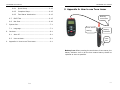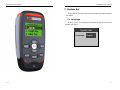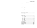
1
TPT-8020A User manual
Contents
1
Introduction ............................................................1-1
2
Appearance .............................................................2-1
3
Verification..............................................................3-1
3.1
Unpacking the tester ........................................3-1
3.2
Package Checklist ............................................3-1
3.3
Power Supply ..................................................3-2
3.4
Power On and Self Check ..................................3-2
4
User Interface .........................................................4-1
5
Interface and Menu Management ...............................5-1
6
Function Description .................................................6-1
6.1
Jack ID...........................................................6-1
6.2
Cable Test.......................................................6-1
6.2.1
Cable PASS .............................................6-3
6.2.2
Open .....................................................6-4
6.2.3
Short .....................................................6-6
6.2.4
Miswire ..................................................6-7
6.2.5
Split Pair ................................................6-8
6.3
Length Test .....................................................6-9
6.4
Tone Generator..............................................6-10
6.5
Flash Link LED...............................................6-10
6.6
Ping Test ......................................................6-11
V1.4
TPT-8020A User manual
TPT-8020A User manual
7
9
Quick Setup ......................................... 6-12
6.6.2
Complete Setup .................................... 6-12
6.6.3
Test Status Introduction......................... 6-13
6.7
DHCP Test .................................................... 6-15
6.8
Net Scan ...................................................... 6-16
9 Appendix A: How to use Tone tracer
Nothing
connected!
System Set............................................................. 7-1
7.1
8
6.6.1
Language ....................................................... 7-1
Cautions................................................................. 8-1
8.1
Auto-off ......................................................... 8-1
8.2
User set data .................................................. 8-1
Appendix A: How to use Tone tracer........................... 9-1
Press while
testing
Battery
Indicator
Hear
vice
Battery Low: When pressing the test button of tone tracer, the
battery indicator turn on all the time means battery should be
replaced as soon as possible.
V1.4
9-1
TPT-8020A User manual
3 Verification
TPT-8020A User manual
1 Introduction
Verification is necessary before you begin using the tester.
This chapter provides an overview of your tester.
3.1 Unpacking the tester
Before unpacking, please check whether there is any
damage in the carton. If any, verify all parts per the packing list
or Section 3.2 and perform self-check per Section 3.4 till in the
new tester is in normal operation.
In case that damaged bag or incomplete parts happen or the
tester cannot achieve function tests, please report to us
immediately
3.2 Package Checklist
TPT-8020A tester kit includes:
Part
Quantity
TPT-8020A tester
1
Remoter
1
RJ11 to RJ45 cable
RJ45 to RJ45 cable
The TPT-8020A is an easy-to-use and portable test set with
advanced cable locator and simple network tester in one unit.
Besides identifying wiremap, measuring the cable length,
diagnosing cable faults for opens and shorts etc. and tracing
cables, the TPT-8020A can also be used to detect the outlet
connectivity and device types, i.e. PBX and Ethernet, etc. and
generate distinctive tones for tracing cable termination in the
wall, ceiling and DDF. Besides, its has comprehensive network
test functions, including static and dynamic (DHCP) IP
configuration, PING test for connectivity to network devices
through ICMP network protocol, and NetScan for scanning
active hosts in the LAN with detected host quantity and IP/MAC
address displaying, thus allowing easy management of LAN.
Main Function
For twisted-pair, coax cable and security wire , etc testing
Intuitive LCD display of wiremaps
Conduct tests of STP/UTP and diagnoses faults for opens, shorts and
2
miswires
2
RJ45 to Alligator clip cable
2
Quick start card
1
User manual
1
Battery
1
3-1
Perform cable tests per T568A/B standard
Maximal cable length for testing: 457 meters
Test several cables simultaneously by selecting multi-remoter
Quick identification at unknown RJ45 jacks
Support static and dynamic (DHCP) IP configuration
Ping test to detect faults, i.e.packet loss
Find active device with NetScan function
Blinks link indicator to identify cable termination on hub or router
Generates selectable tones on selected pins for use with tone tracers
LCD displayer with backlight
1-1
TPT-8020A User manual
8 Cautions
8.1 Auto-off
The tester turns off automatically when none key was
press for a long time. LCD back light will turn off after 5
minutes. The tester will turn off after 15 minutes in all modes
except Tone Generator, which is 60 minutes, and Flash Link
LED, which is 30 minutes.
8.2 User set data
To preserve user set data, the tester must be off by holding
[POWER] key, and the battery disconnected for no more than
one minute.
8-1
TPT-8020A User manual
2 Appearance
2-1
TPT-8020A User manual
TPT-8020A User manual
7 System Set
Press [SETUP] in the main menu the tester will enter system
set mode.
7.1 Language
Press [←] or [→] to change the system language. This is the
system set menu:
System Set
Language: English
2-2
7-1
TPT-8020A User manual
3 Verification
Verification is necessary before you begin using the tester.
This chapter provides an overview of your tester.
3.1 Unpacking the tester
Before unpacking, please check whether there is any
damage in the carton. If any, verify all parts per the packing list
or Section 3.2 and perform self-check per Section 3.4 till in the
new tester is in normal operation.
In case that damaged bag or incomplete parts happen or the
tester cannot achieve function tests, please report to us
immediately
3.2 Package Checklist
TPT-8020A tester kit includes:
Part
Quantity
TPT-8020A tester
1
Remoter
1
RJ11 to RJ45 cable
2
RJ45 to RJ45 cable
2
RJ45 to Alligator clip cable
2
Quick start card
1
User manual
1
Battery
1
3-1
TPT-8020A User manual
TPT-8020A User manual
3.3 Power Supply
The TPT-8020A use 9V typical battery. When the battery low
icon which display on the top right is flashing, the battery should
be replaced as soon as practical.
Press marking “OPEN” lock and push down the battery cap,
then pull out battery snap and connect a new battery. Don’t pull
the battery line directly when replacing the battery.
Scan
progress
Net Scan
Scan:018
Found:005
Amount
of found
devices
3.4 Power On and Self Check
When first time you use the tester must run a self-test as
follows:
Step
Operation
Explanation
1
Install a
new
battery
Tester will turn on and display
welcome interface, then run
initialization and display main menu.
Note:Disconnect any cables when
The tester stops scan when it gets to the end of the IP range.
User can press [OK] to interrupt a scan progress. Press [↑]or[↓]
to see the device’s IP and MAC.
Example:
Amount
of found
devices
See number
001/005
running in initializing.
IP:192.168.001.009
2
Check
battery
status
Press [SETUP] key in main menu to
display the battery capacity and
enter system setup menu. Press
[ESC] key return to main menu.
MAC: 00E04C582D84
Note:Maximal records can save 255 devices’ information.
3-2
6-17
TPT-8020A User manual
Try times for
connecting
DHCP host.
TPT-8020A User manual
4 User Interface
DHCP Test
The TPT-8020A tester is very easy to use. To help you make
full use of its extensive and flexible testing capabilities, please
read through this chapter carefully.
Requesting…
Try:3
Link Indicator
If got response from the DHCP host, LCD display as follow:
DHCP Test
Got response!
Cursor
Got a IP for
the tester
Keys:
Menu
selection, Scroll and
Backlight
LCD
adjust values
My:192.168.001.002
OK
Press OK to Ping
Key:
Enter
Power Key: Short
into a test mode
press
or move to next
Press [OK] once to ping the DNS server; Press [OK]twice to
ping the Gateway; Press[OK] thrice to ping a target IP. Press
[SETUP] to set the target IP.
6.8 Net Scan
to
control
back light. Hold to
screen.
turn off/on tester.
Setup Key:
:Set
ESC:Return to
parameters
higher
level
menu
You must press [SETUP] to set the IP range before a new
test. Press [ESC] return to net scan mode after set the range,
then press[OK] to start a scan test. The follow screen display
that the tester is scanning:
Battery
Cap :
Press lock and
push down
6-16
4-1
TPT-8020A User manual
Tx: transmit packets; Rx: receive packets. If the two
values are not the same, it means that some packets
may be lost.
D. IP Conflict
When the tester’s IP has been used by other devices, the
LCD displays “MyIP is used!”。
E. No ARP response
In case the target IP devices in the network are not
being in use or switch off, the tester will display “No ARP
response”.
F. Ping Fail!
Because
of network problem or intercepted by
Firewall, no ping packets response。
6.7 DHCP Test
In DHCP test mode, the tester can get its network
information, including tester’s IP ,DNS server’s IP
and
Gateway’s IP from a DHCP host. Press [OK] to ping these
devices.
When the tester find an active link, it will display as follow:
6-15
TPT-8020A User manual
TPT-8020A User manual
5 Interface and Menu Management
First time power on the tester will display “initializing” and
then the main menu in 8 sec.
B. Doing ping test:
When detecting an active link,the tester will start
test automatically, See the below display:
Ping
Main menu
1.Jack ID
Ping Test
2.Length Test
My:192.168.001.009
Testing
<<<Function>>>
3.Cable Test
Ta:192.168.001.010
Press [↑] or [↓]key to select a function in the main menu,
Ping…
and press [OK] key to start the selected function. Press [ESC]
key can return to main menu in any function.
Function Table:
C. Ping OK:
When a response is received:
Ping Test
1.
Jack ID
Indentify possible conditions of an RJ45 jack
2.
Length Test
Test cable length
3.
Cable Test
Test cable for shorts, opens and split pairs,
My:192.168.001.009
display wiremap.
Ta:192.168.001.010
4.
Tone Generator
Generate Tone on all pairs of cable
Ping OK!
5.
Flash Link LED
Blinking a link indicator to find a HUB or switch
<=1ms
port
If Ping succeed, the tester display numbers of packets:
6.
Ping Test
Ping to verify connectivity of devices
7.
DHCP Test
Dynamically
acquire
IP/DNS
host
and
Gateway and detect network connectivity
Ping Test
6-14
My:192.168.001.009
Ta:192.168.001.010
8.
Net Scan
Scan active devices in the LAN
5-1
TPT-8020A User manual
IP), Target IP,Gateway and Subnet Mask and view the MAC
physical address of the tester.
Ping Set
MyIP:
1192.168.001.008
Operations:
A. Press [←] or [→] to move the cursor;
B. Press [↑] or [↓] to change the value;
C. Press [OK] to select:
MyIP->Target IP->Gateway->NetMask->MAC;
D. Press [ESC] return to Ping Test mode.
6.6.3
Test Status Introduction
A. Link not Found:
The cable was disconnect or no device on the other end:
Ping Test
My:192.168.001.009
Test result
Ta:192.168.001.010
Link not Found!
6-13
TPT-8020A User manual
TPT-8020A User manual
address of the tester must be set first. If these two address are
not in the same LAN , the gateway and subnet mask should be
set, too.
6.6.1
Quick Setup
For easy to use,please set the tester’s IP and the target IP
follow these steps:
A. Press [OK] to select the tester’s IP with the selected value
highlighted;
B. Press [←] or [→] to go to the number of IP address to be
modified and press [↑] or [↓] to change the value;
C. Press [OK] key again,and select the target IP;
D. Set the target IP according to B,then press [OK] to escape
and start a ping test.
Example:The following diagram shows modifying the last
value of the tester’s IP:
Ping Test
Tester’s IP
My:192.168.001.008
8
Target IP
Ta:192.168.001.010
Ping…
6.6.2
Complete Setup
In the Ping test mode,press[SETUP] key to enter the Ping
6 Function Description
Press [POWER] key to power on the tester,then select a
function to begin test. To turn the tester off, hold [POWER] key
until the display turns off. The tester can save the last testing
state after power off. When connecting to unknown jacks or
cables, it is best to begin with Jack ID test mode. The following
chapters will take you through every test function in details.
6.1 Jack ID
The Jack ID test identifies what equipment connected to the
other end of the jack or cable. The test first looks for voltage
being present on the connector pins. If voltages are found in the
telephone volt range, the LCD will display this voltage.
If no voltage is detected, test for the Ethernet link pulse. If
the link pulses are detected, the tester will report the Ethernet
information, i.e. speed. The tester default cable for connecting
is the straight through cable. In case the network card is
connected to the other end of the cable, the tester will display
“NIC”, while HUB or SWITCH is connected, the tester will display
“HUB or SWITCH”.
Warning, if you use the crossover cable to connect the tester,
the tester will incorrectly display “HUB or SWITCH” instead of
“NIC”. In the case where the tester reports "Auto MDI/MDI-X', it
means the remote device supports auto-adapting crossover and
straight through cables.
The tester will display “POE Equipment!” if a POE(Power over
Ethernet) device is connected. Such equipment typically
provides power for IP-phones or wireless transceivers on the
same wires that carry the Ethernet data signals.
Setup screen, in which you may modify values of My IP(tester’s
6-12
6-1
TPT-8020A User manual
TPT-8020A User manual
this function to trace its termination. The tester flash the link
LED indicator on the port of HUB or switch.
IP-Phone
POE equipment
SWITCH
The tester will first find an active link entering this function
interface. See the display:
Flash link LED
Find link…
If the tester connects to a POE cable like this:
If an Ethernet link is active, the world “Flashing” will be
displayed on LCD and LED on the tester flashes simultaneously.
Flash link LED
The tester will display that a POE device has been detected:
Link found.
Jack ID
Flashing!
POE Equipment!
100BASE-TX full
HUB or SWITCH
6.6 Ping Test
Press [OK] to start a new test.
6-2
Ping test is for testing the network connectivity using the
ICMP protocol. Before IP testing, the IP address and the target IP
6-11
TPT-8020A User manual
TPT-8020A User manual
Press [OK] repeatedly to select a wire pair to be tested, See
the display below.
Test
Length Test
Unit:50.0pF/m
Unit:50.0pF/m
Pair:
Pair:3-6
3-6
Len: 1.5m
Len:
1.5m
6.4 Tone Generator
The tester can generates audio tones for use with tone
tracers on all pairs, a selected pair or a selected pin in this mode.
6.2 Cable Test
Connect a remoter to one end of the cable and the tester to
the other end for a full cable test. Without remoter on the other
end,the tester will automatically perform the one-end test.
One-end test mode can only diagnose cable faults for shorts and
split pairs, but unable to display the wiremap. The tester will
automatically perform a new test every 3 seconds with “Testing”
displaying. If you connect a cable immediately at that time,
you’ll only get the incorrect result. You’d better connect the cable
to be tested before testing.
See the connection diagram below.
Press[↑] or [↓] to select wires or wire pairs for tone sending.
Do not connect the remoter and other devices to the other end of
the cable. Select the single wire can get the strongest signal.
Remoter
Press[←] or [→] to change tone:High,Low,Tone1,Tone2
6.2.1
Tone Generator
Pin: 12345678
Cable PASS
If the cable conforms to the T568A/B ,the tester will display
“PASS” and report cable length. If the remoter was connected,
the tester will display its serial number. ‘S’ at the end of the wire
map means the cable is STP.
Tone:High
Cable Test
6.5 Flash Link LED
When a cable connected to a switch or HUB, you can use
6-10
Serial
Number of
Remoter
12345678S
R1 12345678S
PASS!
1.5m
Wiremap at the
tester end
Wiremap at the
Remoter end
6-3
TPT-8020A User manual
TPT-8020A User manual
6.3 Length Test
See the below diagram of correct wire arrangement per
T568A/B.
The length test function measures the length of a cable by
measuring its capacitance, it is supported in one-end test mode.
The capacitance per unit length can be adjusted. When test a
cable un-crimped, user can use the RJ45 to Alligator clip cable,
and set pair “1-2”. The tester automatically runs a new test
every second. The LCD displays is shown below:
Length Test
Unit:49.0pF/m
One-end Test pass cable ,tester displays as follow:
Pair:1-2
Test result
Len: 1.5m
Cable Test
Press[↑] or [↓] to adjust the capacitance per unit length,
and the tester will display as follows:
One-end Test
Length Test
PASS!
6.2.2
1.5m
Open
This error can only be detected with remoter in the manner
of pairs, which are wired to T568A/B as 1&2, 3&6, 4&5 and 7&8.
The tester will report “Open” when any wire is not attached to a
pin correctly.
6-4
Unit:50.0
50.0 pF/m
Pair:1-2
Len: 1.5m
For cables of unknown capacitance per unit length, a cable of
known length of the same kind will be as the cable whose length
is to be measured is connected to the tester. To reduce the error
at maximum, it is suggested to use the cable above 20 meters.
6-9
TPT-8020A User manual
6.2.5
TPT-8020A User manual
Split Pair
The twisted-pair cables are made up of eight wires twisted
together in 4 pairs. T568A/B standard prescribes the pairs:1-2,
3-6,4-5,7-8. A split pair cable is wired with correct continuity
but not with correct pairing. For a long cable, split pair fault will
greatly affect the signal transportation.
Example:
Example:
For the above situation, the tester displays as follow:
Cable Test
Wires 1-3 are twisted together ,wires 2-6
together,LCD displays is shown below:
Cable Test
are twisted
12345678
R1
345678
Open!
12345678
R1
12345678
Split:1236
6-8
“Open” will be displayed on the last line, and pin 1&2 for the
corresponding pair at the remote end won’t be displayed.
6-5
TPT-8020A User manual
6.2.3
TPT-8020A User manual
Short
When two wires or more are attached to each other, the
tester is able to detect shorts , report it at the bottom of the
screen with the corresponding pin numbers and scrolling
display for shorts of multi-pairs. If a remoter is connected to the
other end of a cable, a ‘+’ will be displayed in the position under
the numbers of short pairs, while one-ended test only displays
“shorts: pin number” instead of wiremap.
6.2.4
Miswire
Miswire : A wire or more wires are not connected to the
correct pins at the other end of the cable. There is one special
kind cable ,1-2 pair on one end to the 3-6 pair on the other. This
cable can be used to connect the two PCs. If miswire was
detected, the LCD will display “Miswire” on the last line. The
one-ended test mode doesn’t support this function.
Example:
Example:
For above situation, see below:
Wire 2 is connected to wire 3 on the other end. See the
displays below:
Cable Test
Cable Test
12345678
12345678
R1
123456++
R1
13245678
Miswire!
Short:78
6-6
6-7