1
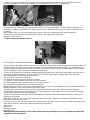
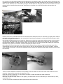
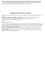
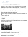
Electronic Fan Controller for Lotus Elise Installation Manual
This Electronic Fan Controller allows you to set a desired temperature for the fan to kick in. While monitoring the coolant
temperature the fan controller also monitors the wheel speed to prevent the fan from over revving and thus preventing it
from breaking.
Normally, the fan is controlled by the ECU which is set to approx 105° C. In our opinion, this temperature is too high. The
switch which is installed on the column shroud & allows you to set the temperature to a desired level. After setting up, the
fan controller will provide a safety barrier to prevent a potential head gasket failure and head "softening" caused by
overheating the aluminium cylinder head.
We advise you to read this manual very carefully and exactly follow the instructions.
The fan controller needs to be wired into the instrument and ECU loom, if you have any questions regarding the manual or
the product installation, please don't hesitate to ask at [email protected]
Tools needed:
Scissors, Phillips screwdriver, 12mm drill, 10mm socket, Small ratchet and extension, Combination pliers, side cutter and to
verify the steps you make, we would advise the use of a digital volt meter and a soldering iron (low power electronics
kind)
This is what you should find in the bag:
- Fan controller (black box with wires)
- Six red push on connectors
- Three transparent / yellow push on connectors
- One piece of yellow wire
- The switch assembly with three wires connected to it.
- Several cable ties
As you need to reach into the dash, behind the instrument binnacle, you will need to remove the complete assembly.
The first step is to remove the column shroud between the steering wheel and the instrument binnacle. The column
shroud is two separate pieces which are screwed together. The shroud is attached to the steering column at the bottom.
Remove the bottom screws first, and then remove the two screws on the left and right hand side near the instruments and
last remove the two screws on front of the column shroud. (if you have the original steering wheel installed, you might
need to turn the wheel to see these last screws.)
The bottom part of the column shroud will come down but will be stopped by the wires connected to the odometer reset
button. The top part will probably be trapped under the instrument assembly.
You can now undo the two bolts at the bottom of the instrument assembly. Removing these bolts will release the binnacle
including the instruments and will also allow you to remove the top part of the shroud.
Lift the binnacle slightly and squeeze your hand in so that you can reach the connector at the back of the instruments.
Have a good look at the next two pictures, there's a latch on top of the connector (in the centre) which needs to be
squeezed to come loose. The connector can be VERY tight, wiggling and pulling is the only thing you can do here. Don't
use any tools!
Store the Instruments in a safe place to prevent any damage.
You will now have a clear view to the connector which was plugged into the Instrument unit. The cable loom of the
connector is strapped on the dash by a cable-tie. Cut the cable-tie to increase your working space.
.
Some cars have the cable loom very close to the connector of the Instrument pack. You will need as much space as
possible so if needed, cut the black tube which is pulled over the cable loom. Use the scissors, but be careful not to cut
into wires!
After cutting it open, you can use the side cutter to remove the piece of black tube which you've opened up.
You will now have to start wiring the fan controller into the Instrument / ECU cable loom.
(marked A in the picture)
** Please take your time for this!! **
A
First of all take a close look at the picture here.
This is a push fit cable spline which is used to get the power and signal from the cable loom without cutting the cables. To
achieve a proper connection, the wire to be connected to the loom needs to be put in the splice. You can push the wire
through the little hole to be able to control the position. Then snap the splice over the wire that needs to be spliced and
use the combination pliers to push the metal part into both wires.
To prevent any problems, we would not recommend pushing all splices in the loom at the same place. Use some 5cm of
the loom to spread the splices; in this way, the cable loom will stay flexible and the splices can't touch each other.
Start identifying the ground cable in the wire loom.
This is the list of wires you're looking for:
A2 - Ground connects to the wire of the fan controller
A3 - Ignition +12VDC connects to the wire of the fan controller
A5 - Vehicle Speed Sensor connects to the wire of the fan controller
A6 - Temp Sensor connects to the wire of the fan controller
All these wires are located in the top row of the connector (The A row) You can recognize the top row when looking at the
latching mechanism. (Top is at the latching mechanism side).
The wire count on the connector runs from left to right (looking from the front of the connector with the latching
mechanism up). Beware, some pins might have two wires connected to them, take a close look and follow the wire into
the connector before pushing on the connectors.
Use the red connectors for the above mentioned connectors. Please look closely at the previous picture to see how to
make these connections.
Next step is to put the yellow wire which controls the actual fan in place. Open the front bonnet and identify the fuse /
relay boxes on the wheel arch liner.
First thing to do is to get the wire from the front compartment to the cabin of your car. There's a rubber grommet on the
same side of the fuse / relay boxes, under the windscreen (see picture).
Black orange
Green red
Yellow/Grey green
Green/Blue blue
When pushing the connectors in the cable, please look very carefully to see you’re pushing the metal part
straight into the red plastic!!
Use a piece of long stiff metal (welding wire/coat hanger wire) to attach the yellow wire to and push the wire through the
grommet to the inside of the cabin. You can now find the wire below the dash. Now bring the wire to the other side of the
dash. You can attach the wire to the dash by using the included cable ties. Bring the yellow wire into the dash and route it
towards the fan controller. Now connect the yellow wire to the yellow wire on the fan controller using another red
connector.
Remove the screws / bolts which hold the fuse and relay boxes and flip the boxes on their back (by flipping them towards
the inside of the car. Route the yellow wire towards the fuse/relay box and attach it to the cable loom by using the cable
ties which are supplied in the box.
Now identify the blue/grey wire on the relay box. Please have a close look at the picture before pressing in the connector.
You can see in the picture that you will have to remove a little plastic back plate from the relay box, the room between
this plate and the bottom of the relays is rather tight. If you are able to, we would recommend soldering this connection
instead of using a push-on connection. Leave the fuse/relay box where it is now.
Drill a 12mm hole in the lower part of the column shroud. Remove the nut from the switch and lead the wires of the
switch through the hole. Now put the nut over the wires on the rear side and tighten the nut (not too tight!). Lead the
wires towards fan controller. The wires are stripped from their isolation at exactly the right length (as are the wires on the
fan controller).
There are three transparent connectors in the package; these are meant to connect the wires of the switch to the fan
controller. Please have a close look at the pictures to see
Once both wires are pushed in, you can push the connector in which will make the actual connection.
(Picture on the right hand side)
Next step is to test the setup. Switch on the ignition, you should hear now is the fan kicking in. If that's what you hear,
everything is fine!
You can now put the fuse/relay box back in place & close the front bonnet.
Now use some white spirit or similar to degrease the surface of the black plastic box you can see in the opening of the
dash. After degreasing and cleaning the surface, you can stick the fan controller on this box. Now put the instruments
back in place. Don't forget to push the connector in! Note how far you've got the push the wires in the connector.
Put the column shroud back in place and you'll be ready to program the fan controller!!
Operation manual for the fan controller
Power on test: when the ignition is switched on, the LED in the switch will blink 3 times and the fan will kick in for a split
second.
* Push button for approx. 10 seconds until the LED is steadily lit. As soon as you release the switch, the actual
temperature will be stored as the temperature to start the fan.
* Push button for approx. 20 seconds (after 10 seconds, the LED is on, after 20 seconds the LED
switches off) to apply a factory reset. (approx. 90 deg.C)
Operation:
Tips for programming and usage:
* The factory default is set at approximately 90 deg.C* when you would like to set a temperature above 90 deg.C, the fan
will kick in at a certain point. As this will start cooling the engine, it might be a little hard to reach the desired temperature.
A way to overcome this is to set the temperature in steps. (first time set the temperature at 94 degrees, then do another
cycle and set the temperature to the desired level.)
* When the fan has been enabled, the controller will cool down the coolant temperature to the set temperature less 4
degrees. After reaching the temperature, the fan will be switched off and the LED in the switch will start blinking for
approx. 30 seconds.
The fan controller also monitors the vehicle speed. If the car is moving faster then approx. 40kmh/26mph the fan will be
switched off to prevent overheating of the fan motor.