1
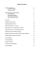
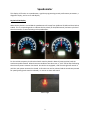
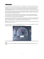
TOMBERLIN® CONSUMER DISCLAIMER Tomberlin® reserves the right to change the suggestions gained in this consumer support site. It is intended primarily for educational purposes only. Some experienced consumers prefer to do the maintenance and service themselves, for the "Do It Yourself" owners, Tomberlin strongly encourages interaction with your local dealer first and to never attempt a procedure you are unfamiliar with safely performing. An electric vehicle has a significant voltage that can result in shock, fire and injury if not performed by a professional. Damage to the vehicle can also occur. Some procedures require specific torque settings that when not followed can result in dangerous, possibly life threatening situations. Many errors will not surface immediately. The information herein has generally proven to enhance the life cycle, safety and overall ownership experience when properly followed. Tomberlin assumes no liability for the content provided in this consumer educational section and it is possible that an error with regard to spelling, grammar, nomenclature, and translation is present. Note that the information provided should be treated as live documents meaning they are always in a state of refinement, correction and improvement. Check back often and if printed, check back prior to reliance to assure they remain current. Never attempt to manipulate the vehicle to exceed the speed as required by regulations. The highest speed range for Tomberlin® E‐Merge™ PTV's and LSV's are factory set at 15‐19 mph as a PTV or 22‐25 mph as an LSV. Consumers should always exercise prudent common sense measures, use proper safety gear with tools designed specifically for the task. Always utilize insulated tools around electrical connections. Never exceed your comfort level and when in doubt, stop and call your local dealer. Tomberlin Authorized Dealers are always your best resource. If you notice an error or have an idea that will improve our efforts here, please email your idea to [email protected]. Table of Contents
Function of Speedometer
Key Switch On Display
Viewing Error Codes
3
3
4
Diagnostics & Parameter Programming
Speed Adjustment
Acceleration Adjustment
Electrical Braking Adjustment
Motor Speed Sensor Testing
5
5
7
7
8
Error Codes
9
Troubleshooting Error Codes
10
Checking Motor Speed Sensor
15
Motor & Controller Test – connected
16
Isolated Motor Test – disconnected from controller
17
Isolated Controller Test – disconnected from motor
17
Installing KC Host, AC Download, and Logger
18
Changing Setup Parameters or Retrieving Error Codes using KC Host
24
Programming New Software into Controller
31
Running KC Logger
37
Un-installing KC Host
40
Controller Installation
43
Controller Connection Definition
51
Various Schematics
51
2
Speedometer
This display will function as a speedometer, a guide to programming certain performance parameters, a
diagnostic display, and an error code display.
Key Switch ON Display
When the Key Switch is turned ON the speedometer will sweep from 0 MPH to 25 MPH and then back to
0 MPH. This is a simple diagnostic to indicate the key switch (or RUN/TOW switch) has been cycled and
that the controller is communicating to the speedometer.
For the vehicle to operate, the Direction Switch must be placed in Neutral (center position) and the
accelerator pedal released. When these two conditions have been met, a “click” will be heard indicating
that the main power contactor has closed. On vehicles so equipped, a red Thermal Light will remain lit
until the main power contactor has closed. A direction can now be selected and the accelerator pressed
for speed (parking brake must be released). In reverse an alarm will sound.
Themal Light
3
Viewing Error Codes
In the unlikely event that there is a vehicle or control malfunction, error codes will be displayed on the
speedometer. The error code will be indicated on the speedometer only when the directional switch is
placed in neutral. However, all error codes are saved in memory and can be viewed by entering the
error viewing mode at anytime. To enter the mode to view the stored error codes, the key switch needs
to be initially turned to the OFF position. Next, the key switch needs to be turned ON/OFF 4 times within
5 seconds, and left in the ON position the fourth time (ON/OFF – ON/ OFF – ON/ OFF – ON). The main
power contactor should not pull-in (no click).
If the main power contactor does come in then the vehicle is in the normal driving mode, and not in
error viewing mode. Re-try by initially turning to the OFF position and cycling the key switch ON/OFF
four times within 5 seconds and leaving in the ON position.
On the fourth ON, the speedometer will indicate the most recent error code, and each push of the Turbo
button will cycle to the next error code. When the speedometer goes to 0 MPH it is an indication that
all error codes have been seen. A total of 8 error codes are saved in memory.
(NOTE: If the speedometer indicates 0 MPH regardless of how many times the Turbo button has been pressed, then
there are NO error codes stored).
The example below is the display indicating 18 MPH (which is a motor overheating condition). To exit
this mode, simply turn the key switch to the OFF position.
Refer to the Error Codes section on page 9 for the error code per speedometer value for full error code
details.
(NOTE: Error codes will also be flashed on the Thermal Light on the speedometer (if equipped) in long and short
bursts).
4
Diagnostics and Programming
The Anvil vehicle is set up so that quick troubleshooting of switches and harness connections, and some
basic programming, can be achieved by using the Speedometer and the Turbo button. It is
recommended to initially set the Parking Brake, which should light the parking brake light on the
instrument cluster. When placed in reverse the back-up alarm should sound. If the instrument cluster is
equipped with a Thermal Light, the light will flash during Diagnostics and Programming.
Items like no forward or no movement without an error code may be wiring or a switch failure. It is
always suggested that for any problem that occurs without an error code that self diagnostics be
completed. If the results of putting these switches in the positions indicated do not result in a reaction
of the speedometer, one can hopefully determine which switch is, or is not, working, so that the switch
and wiring can be appropriately troubleshot and repaired.
Speed Adjustment
To enter the Diagnostics and Programming mode the key switch needs to be turned on 3 times within 5
seconds, and left in the ON position the third time – ON/OFF – ON/ OFF – ON. The main power
contactor should not pull-in (no click). If it does the vehicle is in the normal driving mode, and not in
Diagnostics. Try cycling the key switch again 3 times in less than 5 seconds. The speedometer needle
will now register certain switch activations and deactivations. The Thermal Light (if equipped) will flash
three times indicating that the vehicle is in Diagnostic and Programming Mode. The default display,
when the speed should indicate zero MPH is:
Directional Switch in center position – Neutral
Foot off of the accelerator and brake pedal
The main controller monitors the Directional switch, the Brake Pedal switch, the Accelerator Pedal
switch and potentiometer, the Economy/High Performance switch, and the Turbo button. If the display
shows a speed between 5 and 25 MPH at least one of the switches may be activated. If zero speed
cannot be achieved, then one needs to determine which switch is stuck in the ON position. By placing
the Directional switch in FORWARD the speedometer will display whatever speed that has been
5
programmed for HIGH PERFORMANCE or ECONOMY settings. For example if HIGH PERFORMANCE and
FORWARD have been requested, the display will display 25 MPH (default setting). If this does not occur,
it may be indicative of a switch failure.
On the other hand, if ECONOMY and FORWARD are selected, the speedometer will display 20 MPH
(default setting).
While in FORWARD and ECONOMY or PERFORMANCE, pressing the TURBO button will reprogram the
speed setting, and the speedometer needle will indicate what the speed has changed to. For example, if
in FORWARD and PERFORMANCE, pressing the TURBO once will move the needle to 20 MPH, pressing
again will increment 1 MPH for each TURBO button depression. Where ever the speed is left will be the
programmed value.
If FORWARD and ECONOMY are requested, pressing the TURBO will move the speedometer needle to
10 MPH, and each depression of the TURBO button will increment from the speedometer from 10 MPH
to 20 MPH.
6
If REVERSE is selected, regardless of the Performance switch setting, 10 MPH (default) will be displayed.
Depressing the TURBO button will decrease to 5 MPH, and will increment towards 10 MPH with each
depression of the TURBO switch. Note that in Reverse the back-up alarm will sound.
The following table shows possible speed settings:
Switch Position
Forward Economy
Forward High Performance
Reverse (alarm will sound)
Default Setting MPH
20
25
10
Speed Range MPH
10 to 20
20 to 25
5 to 10
Acceleration Adjustment
Place the Direction switch to NEUTRAL, the speedometer should return to zero. Press the accelerator all
the way to the floor - speedometer should approach 35 but then fall back to display 10, 15, 20 or 25
MPH. This indicates that the potentiometer and start switch in the accelerator are functioning correctly,
and that the level of MPH displayed is the acceleration rate. The higher the MPH number the quicker
the acceleration will be. Rapid accelerations will reduce battery charge life and distance of travel. By
pressing the TURBO button the level of acceleration will change, keep pressing until the desired level is
reached. If you do not see the accelerator go above 25 MPH it may be indicative that the accelerator
potentiometer is not reaching full voltage, which may limit top travel speed.
Electrical Braking Adjustment
Place the Direction switch in NEUTRAL and release the Accelerator Pedal, the speedometer should
return to zero. Push down on the Brake Pedal - speedometer will indicate 10, 15, 20 or 25 MPH. This
indicates that the brake pedal switch is working, and that the level of MPH displayed is the amount of
electrical braking. The higher the MPH the shorter the stopping distance when the brake pedal is
depressed. By pressing the TURBO button the level of electrical braking will change, keep pressing until
the desired level is reached. 25 MPH is aggressive braking, while 10 MPH is softer and will require
longer distances to stop the vehicle.
Motor Speed Sensor Test
One final diagnostic test is the ability to ensure that the motor’s speed sensor is working. Make sure
that the Directional switch is in NEUTRAL, and the speedometer is displaying 0 MPH. Ensure that the car
is on flat ground and not in danger of rolling away. Release the parking brake and gently push the car
either forward or reverse. As the controller senses the two signals from the speed sensor the
speedometer should display the following:
7
0 MPH – neither channel is registering – could be 15 volt or BATT NEGATIVE wire broken.
5 MPH – Channel A failure – check J10-6 and pin 3 of 4 pin connector from motor JM4.
10 MPH – Channel B failure – check J10-3 and pin 2 of 4 pin connector from motor JM4.
15 MPH – Both channels functioning, maybe problem is elsewhere or intermittent.
(NOTE: On older software revisions (pre-2.44/3.44) the speedometer would indicate a speed dependent on how
fast the vehicle was pushed, and could not determine if speed channel A or speed channel B were not recognized).
Check voltages at JM4B from the controller. JM4B-1 should be 15 volts. JM4B-2 & JM4B-3 should
switch between 0 volts and 15 volts. JM4B-4 should measure zero volts, and if a continuity test is run
should be connected to BATTERY NEGATIVE.
(NOTE: Complete wiring diagrams and references to J10, JM4B-1, JM4B-2, JM4B-3, and JM4B-4 can be found on
page 48 of this manual).
8
Error Codes
If the vehicle is equipped with a (red) Thermal Light it will flash a fault codes when they occur – count
the number of flashes, there are short quick flashes and long slow flashes. This flash code will also
appear on the controller itself and can be read if the plastic cover over the controller area is removed. If
it is not equipped with this dash light, the fault code will be indicated on the speedometer when the
forward/reverse switch is placed in neutral, or can be recalled using 4 key ON cycles and using the Turbo
button to scroll through up to 8 stored error codes.
Low Priority (Line Contactor enabled - will not disable system and error code will not be saved in
memory):
Speed
0 mph
4 mph
5 mph
6 mph
7 mph
8 mph
Flash Code
0
0 long 1 short
0 long 2 short
0 long 3 short
0 long 4 short
0 long 5 short
Description
No Fault
Low Battery 1
Low Battery 2
Motor Temperature Warning 125 C (257 F)
Controller Temperature Warning 110 C (230 F)
Forward and Reverse requested simultaneously
High Priority (Line Contactor disabled, error code will be saved in memory):
9 mph
10 mph
12 mph
14 mph
15 mph
16 mph
17 mph
18 mph
19 mph
20 mph
21 mph
22 mph
26 mph
28 mph
30 mph
32 mph
0 long 6 short
Phase over current fault – too much phase current
0 long 7 short
Battery fault – battery voltage too high over 100 volts
0 long 9 short
Phase Error – phase not turning on
1 long 1 short
Fault Latch Failed 1 – multiple failures
1 long 2 short
Pre-charge Failure1 (if Capacitors haven’t reached 2 Volts after
20 milliseconds of pre-charge)
1 long 3 short
Pre-charge Failure2 (if Capacitors haven’t reached the precharge lower limit voltage after 1 second of pre-charge).
1 long 4 short
Low Battery – voltage while running
1 long 5 short
Motor overheated 135 C (275 F).
1 long 6 short
Controller overheated 120 C (248 F)
1 long 7 short
Throttle Fault – Start switch and or potentiometer not in sequence
1 long 8 short
Software Version incorrect
1 long 9 short
Over Current Fault on controller output
2 long 1 short
EEPROM/Internal Memory Failure
2 long 2 short
Speed Sensor channel A failed
2 long 3 short
Speed Sensor channel B failed
2 long 4 short
Speed Sensor channel A & B failed
9
Troubleshooting Error Codes
Error codes will only occur under certain conditions. Items like no forward or no movement without an
error code may be wiring or a switch failure. It is always suggested that for any problem that occurs
without an error code that self diagnostics be conducted. See Diagnostics and Programming.
Error Codes:
4mph
0 long 1 short flash
Low Battery 1 – Charge the Battery
Controller measures battery voltage at J16-1 after the key switch is turned on, but before the line
contactor closes. If this is less than 63 volts (default, but programmable) this code will occur. 63 volts
for a 72 volt battery is very low, and performance on the car will be severely limited. Measure the
voltage across the battery terminal. If this is significantly higher, then troubleshoot and find where the
voltage is dropping. RUN/TOW switch provides voltage to J16-1, with switch in the TOW position
battery voltage should be on one side of switch. With switch in the RUN position, battery voltage will be
on both sides of the switch. Charge the battery if less than 71 volts.
The 63 volt level can be increased or decreased using KC Host.
5mph
0 long 2 short flashes Low Battery 2 – Charge the Battery
Same as above, but voltage at J16-1 is less than 58 volts. Car will most likely not run very well before
error code 14 occurs. Suggest charging the battery before this error code appears!
The 58 volt is default level can be changed using KC Host.
10
6mph
0 long 3 short flashes Motor Temperature Warning 125 C – Let cool
Controller continuously monitors temperature of the motor through JM2, and to J10-1 and J10-2. At
room temperature resistance within motor is approximately 570 ohms. At 100 degree C it is
approximately at 1000 ohms. Performance of controller will be reduced; if temperature continues to
raise controller will shut down system with flash 1 long 5 short (18MPH). If this connector is corroded,
or has bad connection, or this connector disconnected this error code may occur prematurely. Let
motor cool, or drive at a slower rate. Check battery voltage for charged battery, ensure brakes are not
dragging. The motor’s two pin thermal connector JM2 is shown below:
Motor Thermal Connector
7mph
0 long 4 short flashes Heat Sink Temperature Warning 110 C – Let cool
Internal to the controller the transistor heat sink is monitored. Performance will start to reduce, and if
temperature continues to raise, flash code 1 long 6 short (19MPH) may occur and the vehicle will shut
down. Ensure battery is well charged, brakes are not dragging, and that controller is securely fastened
to mounting plate. If this occurs with a “cool” controller the problem is internal to the controller and
the controller will need to be replaced.
8mph
0 long 5 short flashes Forward and Reverse requested together
If the controller sees both the FWD and REV simultaneously it will default to NEUTRAL. Directional
switch and/or wiring need to be repaired. Battery voltage has been applied simultaneously to controller
connector J12-9 and J12-10.
11
High Priority (Line Contactor disabled and saved in memory):
9 mph 0 long 6 short flashes
Phase over current fault
Under normal circumstances this flash code should not appear – over 600 amps in at least one phase of
the motor. It is possible due severe driving conditions, and heavy motor loads this error code may
occur. If it occurs repeatedly, or as soon as the car is moving, either the motor or controller may have
failed. With RUN/TOW off, perform motor and controller tests with them connected together and
separated if necessary. See motor and controller tests at the end of fault codes.
10 mph
0 long 7 short flashes Battery voltage too high
If the voltage at the controller exceeds approximately 100 volts, this error will occur. With a fully
charged battery, electrically braking or speed controlling down a steep hill, this may occur to prevent
catastrophic failure of the controller. Ensure that battery charger is not exceeding its charging voltage,
and end of charge battery voltage should not exceed 98 volts. This voltage should diminish to about 85
volts as the battery cools. A fully charged battery cannot accept large regen currents without the
battery voltage rising. After the battery discharges it is unlikely that 100 volts can be achieved. Also
check for loose connections at BATT + and BATT- cables at controller and at battery. Ensure that no
hardware (steel washers) is between high current carrying conductors. Consider reducing Braking Rate
to a minimum using Diagnostic and Programming procedure.
12mph 0 long 9 short flashes Phase fault (U, V or W)
Controller protection circuitry is preventing phase current. This can be an internal controller fault or a
motor fault or both. Test motor and controller isolated from each other. See below, if both test out OK,
most likely internal controller fault – change out the controller.
14mph 1 long 1 short flash
Fault Latch Failed 1
A fault has occurred but the internal hardware and software cannot determine which fault it is. If it
does not reoccur then do nothing. If it results in another error code, resolve that error code first. If
condition continues ensure software is latest 2.43/3.43, and if the problem continues replace the
controller.
12
15mph 1 long 2 short flashes Pre-charge Failure
Circuitry internal to the controller will pre-charge capacitors internal to the controller. For the main
contactor to pull in, the voltage of these capacitors needs to reach a certain point. Flash code 1- 2
ensures the voltage on the capacitors reaches 2 volts after a very short period of time. If the voltage
does not increase, it most likely is due to a catastrophic failure of the transistors internal to the
controller. Conduct Motor and Controller test – connected, as described at the end of the fault codes.
Also ensure that no auxiliary wiring has been added to the switched side of the main contactor. Any
additional circuit may prevent the caps from charging up in the required time and may cause this fault.
16mph 1 long 3 short flashes Pre-charge Failure 2
Assuming the previous error code has passed, the capacitor voltage needs to reach approximately 12
volts less than Battery Positive in a certain time period. If it doesn’t flash code 1-3 will occur. Recycling
the key switch may resolve this issue, so is a temporary solution. If there is voltage remaining in the
capacitors it takes less time to reach the tested voltages. With the RUN/TOW switch in the RUN
position, turn the key ON, one should see voltage increase on the Batt+ cable attached at the bottom of
the controller. This voltage should also stay for a long time after the key switch has been turned off.
Rapid voltage reduction after the key switch has been turned off indicates something is draining the
capacitors either external or internal to the controller.
Charge batteries, also check voltage at J16-1, this is wire that will charge internal capacitors.
17mph 1 long 4 short flashes Low Battery - voltage is 55% of 72V = 39.6 volts while running – Charge
the Batteries!
Battery voltage is very dependent on the state of charge of the battery, speed of the vehicle, and grade
of road. If battery voltage ever gets as low as 39.6 volts, flash code 1-4 will show. Generally the
batteries need charging.
18mph
1 long 5 short flashes Motor overheated 135 C – Let cool
If 2.xx or 3.xx software is loaded into the incorrect version of the controller, this error will occur. Update
to latest software 2.43 or 3.43 software. Otherwise see flash code 3 above. If J10 at the controller is
disconnected this error code will occur.
19mph
1 long 6 short flashes
See flash code 4 above.
Controller overheated 120 C
13
20mph
1 long 7 short flashes Throttle Fault
For the vehicle to operate after the key has been turned on, the Direction switch must be placed in
NEUTRAL, and the accelerator needs to be released. If the controller measures the throttle switch to be
open, but the voltage on the accelerator potentiometer to be out of range this error code will occur. Or
if the start switch does not close when the accelerator is depressed, this code will occur as the
accelerator is depressed. Measure voltage at J12-13 (throttle switch), this should be zero volts with the
accelerator released, and battery voltage (72 volts nominally) when the accelerator is depressed.
Also measure voltage at J12-5, this is the voltage that the controller uses for speed control. Low voltage
is zero speed, increasing voltage is increasing speed. When it gets to about 3.5 volts you are at
MAXIMUM speed. Throttle switch should close before this voltage gets above 1.0 volt.
21mph
1 long 8 short flashes Software Version Incorrect
Internal to the controller, a memory location is set to indicate that it should be version 2 or 3 software.
If the incorrect software is loaded into the controller, this error code will occur. 2.xx goes into earlier
controllers that do not have the ability to light the Thermal Light. Version 3.xx goes into later controllers
that can light the Thermal Light. Restart the download process again with the correct version of
software.
(NOTE: Prior to doing the original download, it is required by the user to run KC Host to see which original version
of software is installed).
22mph
1 long 9 short flashes Over Current Fault
If the contactor coil becomes damaged (low resistance) the controller may not be able to pull it in, but it
will protect its internal circuitry. If this fault code occurs, check coil resistance of contactor - nominally it
should be 350 ohms. Check resistance between harness side of J16-2 and J16-1 should be 350 ohms.
The error code can also occur if back-up alarm fails or if speedometer fails. Check wires J16-3 and J16-4
for accidental connection to 12 volt +.
(NOTE: Check speedometer and backup alarm with diagnostics procedure, if this error doesn’t occur it eliminates
the possibility that J16-3 and J16-4 may be causing this problem).
14
26mph
2 long 1 short flash
EEPROM/Internal Memory Failure
After downloading of new software, there is a possibility that this error code will appear on power up.
This signifies that the EEPROM/Internal memory has been scanned and an error has occurred. Using KC
Host to change setup parameters, change the “FuncBitmap” to 65535, and then exit KC Host. Cycle the
RUN/TOW switch and the error code should not occur.
(NOTE: If this error code continues to occur, the controller should be replaced).
28mph
2 long and 2 short flashes
Speed Sensor Channel A Failure
Speed sensor channel A has failed to receive speed pulses from the motor. Refer to “Checking Motor
Speed Sensor” section below:
30mph
2 long and 3 short flashes
Speed Sensor Channel B Failure
Speed sensor channel B has failed to receive speed pulses from the motor. Refer to “Checking Motor
Speed Sensor” section below:
32mph
2 long and 4 short flashes
Speed Sensor Channels A & B Failure
Speed sensor channels A & B have both failed to receive speed pulses from the motor. Refer to
“Checking Motor Speed Sensor” section below:
Checking Motor Speed Sensor
Failure of the speed sensor generally results in very slow speed and no speed registration on the
speedometer, and jerky operation. To check the speed sensor in Diagnostics, refer to “Motor Speed
Sensor Test” on page 8.
15
Motor & Controller Test – still connected together
Measure resistance:
U and BATT NEGATIVE Cable (top of controller or at battery) = 10,000 ohms nominal
V and BATT NEGATIVE Cable (top of controller or at battery) = 10,000 ohms nominal
W and BATT NEGATIVE Cable (top of controller or at battery) = 10,000 ohms nominal
U and SWITCHED BATT POSITIVE Cable (lowest controller cable) = Open circuit
V and SWITCHED BATT POSITIVE Cable (lowest controller cable) = Open circuit
W and SWITCHED BATT POSITIVE Cable (lowest controller cable) = Open circuit
U to unpainted metal surface of the motor = high resistance, if less than 1000 ohms this could be a start
of a problem, if less than 100 ohms there is a problem.
Catastrophic failure of the controller generally results in any one or multiple ones of the above readings
measuring very close to zero ohms.
16
Isolated Motor Test – disconnected from controller
Measure resistance between U and V, V and W, and U and W, all should be very low resistance 0.1
ohms.
Measure resistance between U, V or W, and an unpainted portion of the frame of the motor, resistance
should be very high. If less than 100 ohms something has shorted to frame. If below 1000 ohms it may
be a start of something, than may result in a short as the motor heats up, if higher than 10,000 ohms
nothing to worry about.
Measure resistance between the two pins of the JM2 connector – approximately 500-600 ohms at room
temperature, increasing as motor gets hotter.
Measure resistance between pins of JM4 connector (speed pickup), any combination of pins should be
high resistance. Any low resistance, less than 1000 ohms could mean a failure.
Isolated Controller Test – disconnected from motor
Measure resistance:
U and BATT NEGATIVE = 25,000 ohms nominal
V and BATT NEGATIVE = 25,000 ohms nominal
W and BATT NEGATIVE = 25,000 ohms nominal
U and BATT POSITIVE = greater than 100,000 ohms
V and BATT POSITIVE = greater than 100,000 ohms
W and BATT POSITIVE = greater than 100,000 ohms
Catastrophic failure usually results in one or more of the above reading in a very low resistance less than
100 ohms.
17
Installing KC Host, AC Downloader, and Logger
Insert the disc that has been provided, it should start an auto-install. If it doesn’t auto-install, open up
the disc drive, generally Drive (E:), and click on the setup file as shown below.
There is going to be four different programs downloaded, and every computer can be slightly different.
The disc should work with Windows 98, XP, 32 and 64 Bit Vista and Window 7. On more recent
computers a lot more security questions will be asked, continue to click on “allow” “continue” “yes”
and “OK”.
Click “Allow” below:
18
First the USB Drivers will be installed, click “Install” below:
It may indicate that drivers are already installed, if so click “OK”:
After the USB drivers are installed the following screen may appear:
To continue the installation of the other three programs, one may have to click on the setup.exe box
that may be flashing at the bottom of the computer:
19
The installation will now continue with similar screens, click “Allow”:
Click “OK” below:
Click the box high-lighted in RED below:
20
Click “Continue” below:
Two or more of the following screens may show up, click “yes” on all of them, this will use the latest file
available files:
21
The following screen indicates the first of the three programs has installed successfully, click “OK” to
proceed with two more installations. Continue to click boxes as before.
KC Download_AC and KC Logger_USB should both download successfully.
After all these have installed, one should be able to find them within C: Programs Files:
Right click on each of these programs and Copy, then go to your desktop and right click and choose
Paste Shortcut. This will generate the following three Icons onto your desk top.
22
The last step in this process is to attach the USB communicator to allow Windows to enumerate
(recognize) that the communicator is attached.
After attaching, on the bottom right of the Windows tool-bar, a message will pop up saying “windows
has found new hardware” – let this process complete! When finished, another message will pop up
saying “your new hardware is ready to use”.
This can also be verified by launching “Control Panel” / “System” / “Hardware” / “Device Manager” /
“Universal Serial Bus Controllers” and look for the entry entitled “USB Express Device” or “Silicon
Laboratories” (this name may vary between windows XP, Vista, or 7)
23
Changing Setup Parameters and Retrieving Error Codes using
KC Tomberlin Host
To communicate to the controller you will need a communication cable and the correct wire adapter
harness. See above. All Tomberlin cables should be version EA61. This will allow a laptop to talk with
the controller. The black box isolates the laptop from the controller and adjusts the voltages from the
controller voltages to the USB voltages.
One harness (KC Host Adapter) is used to change setup parameters – speeds, acceleration rates, braking
rates etc., while the other adapter (Program Adapter) is used to download a complete new program. As
product updates and improvements are made, or requests for special items are made, new programs
can be downloaded into the controller. Note the differences in the wires, the KC Host Adapter simply
has 5 wires, the Program Adapter has five wires and two loops.
24
Apply the parking brake, turn off the Key Switch, and turn off the power to the controller by using the
RUN/TOW switch mounted on the plastic composite cover over the controller. Slightly above J11 there
are two LEDs a green and a red one. When the RUN/TOW switch is in the OFF or TOW position the
green LED will be OFF, and will turn ON when the RUN/TOW switch is in the ON or RUN position. Key
switch does NOT kill the power to the controller. With the power OFF, connect KC Host Adapter (five
single wires) into J11, the ten pin connector that is blank on the controller. The connector will only fit
one way, note the locking ramp’s position.
Connect the other end into the USB port in your laptop that has already been powered up and running.
Look for the ICON that says KC Host Tomberlin, and double click and say yes and OK to all the Microsoft
questions, until the following screen appears. Sometimes one has to right click and run as
Administrator:
25
While this screen is showing, the number (28) is incrementing indicating how long it has appeared in
seconds (you have 255 seconds to connect), and it is waiting for power to be applied to the controller.
Place the RUN/TOW switch into the RUN position and the following screen should appear:
26
Use your mouse to select “Setup” to change parameters, or “Setup Transfer” to view error codes. The
following screen will appear for “Setup”:
Screen above shows Factory Defaults
(NOTE: In the above graphic, there is the Version level (Version 2.39). This is the version that is currently loaded in
the controller. This will vary dependent on controller revision and software revision. To date, there are quite a few
versions of controller software in the field (2.36, 2.38, 2.39, 2.44 and 3.36, 3.38, 3.39, 3.44)).
There are presently 10 programmable boxes, moving your mouse into the box and typing a number and
hitting enter will change the parameter value.
Fast Speed – this sets that maximum speed in the HP (high performance) values of 20 to 25 are valid.
Slow Speed – this sets the speed in the Economy mode – 10 to 20 are valid.
Rev Speed – this sets the maximum speed in reverse – 5 to 10 are valid.
Accel Rate – this set the acceleration rate - min 10, max 40. The higher the number lessens the time to
maximum speed, and will also consume the most battery amps. Default 20
Coast Rate – this sets the amount of regenerative braking when the accelerator pedal is released. 1
would be a coast, 13 would slow the vehicle the most. Default 2
27
Braking Rate - this sets the amount of regenerative braking that occurs when the service brake switch is
activated (pressing the service brake pedal). 4 is the minimum and 16 is the maximum rate. The
numbers correspond to the same amount of braking that occurs during Coast Rate. Default 8
Min Key On Volts – this is the minimum voltage required at power on for the line contactor to close. 63
to 72 volts is allowed. At any of these voltages the car is not going to travel very far!
SlowDownVolts – this is the voltage (53 to 63 volts) that will sound the back-up alarm as long as you are
below this voltage. During acceleration one may hear a single beep, which will roughly correspond to
when the needle of the BATT Gauge (Green, yellow and red) goes into the RED. As the battery
discharges, more and more beeps will occur encouraging the driver to accelerate slowly, and head for an
electrical outlet.
ShutDownVolts – at 45 volts (programmable) the controller will shut down with an error code, which
may be cleared by cycling the key switch. More than likely this will continue to happen and the vehicle
will be difficult to move.
Function Bit Map – This is an engineer’s way enabling and disabling parameters, it will be changed in the
future. The only reason to use this is to enable or disable the alarm for low battery. 382 disables the
alarm, 894 enables the alarm.
DO NOT ENTER ANY OTHER NUMBERS unless specifically instructed to do so!. For example, some
vehicles may have been made without a Parking Brake switch being wired into the controller, this
function allow you to program around to eliminate the parking brake input.
(NOTE: Entering 65535 will clear/wipe out all EEProm memory locations. This should only be done if the controller
is powered up with a EEPROM/Internal Memory Failure fault).
28
To retrieve the saved error codes, select the “Setup Transfer” option.
The following screen will appear:
Choose “Read Stored Fault Codes” option – the following screen will appear:
29
These can be cleared by selecting the “Clear Errors” box, or can be saved to a file by selecting Save. By
simply exiting the error codes will remain the same. Error codes can also be displayed through the
speedometer (see Viewing Error Codes section on page 4).
Referring back to the Setup section, after setting the parameters to the desired values, and hitting enter
each time, the values have been programmed. Close out the KC Host screen by clicking on the “X” in the
top right hand corner. Turn the RUN/TOW switch to the TOW or OFF position and remove the wire
adapter harness from J11. On a Vista machine one may get the following message:
Simply hit “this program installed correctly” or cancel.
30
Programming New Software into Controller
Prior to programming new software into the controller, the new program files (SINGDSP Ver 2_44.HEX
or SINGDSP Ver 3_44.HEX for example) need to be loaded into your laptop.
IMPORTANT:
Files that are version 2 (SINGDSP Ver 2_44.HEX for example) are designed for controllers that ARE NOT
equipped with the thermal light control.
Files that are version 3 (SINGDSP Ver 3_44.HEX for example) are designed for controllers that ARE
equipped with the thermal light control.
•
Copy the desired .HEX file to:
o
•
C:\Program Files\KC_Download_AC\
Or, in some cases on Windows Vista, Windows 7, this location might be:
o
C:\Program Files (x86)\KC_Download_AC\
These directories can also be found by highlighting the KC_Download_AC icon on your desktop, right
click and refer to the Target field (this will contain either of the above directory paths).
(NOTE: When loading a file into the above location(s) it generally has to be stored in a directory first and cannot be
taken directly from an e-mail. Store the .HEX file in a temporary location first and then copy or drag into the above
directories. Generally it will state you need to “provide administrator permission” - click “continue”, and then
“continue again).
31
To communicate to the controller you will need a communication cable and the correct wire adapter
harness. This will allow a laptop to talk with the controller. The black box isolates the laptop from the
controller and adjusts the voltages from the controller voltages to the USB voltages. For Window’s 7
and Vista 64 bit laptops, the cable should be marked with EA61, as shown above.
One harness (KC Host Adapter) is used to change setup parameters – speeds, acceleration rates, braking
rates etc., while the other adapter (Program Adapter) is used to download a complete new program. As
product updates and improvements are made, or requests for special items are made, new programs
can be downloaded into the controller. Note the differences in the wires, the KC Host Adapter simply
has 5 wires, the Program Adapter has five wires and two loops.
32
Apply the parking brake, turn off the Key Switch, and turn off the power to the controller by using the
RUN/TOW switch mounted on the plastic composite cover over the controller. Slightly above J11 there
are two LEDs a green and a red one. When the RUN/TOW switch is in the OFF or TOW position the
green LED will be OFF, and will turn ON when the RUN/TOW switch is in the ON or RUN position. Key
switch does NOT kill the power to the controller. With the power OFF, connect KC Program Adapter
(five wires and two loops) into J11, the ten pin connector that is blank on the controller. The connector
will only fit one way, note the locking ramp’s position.
Connect the other end into the USB port in your laptop that has already been powered up and running.
Look for the ICON that says KC Download AC, and double click and say yes and OK to all the Microsoft
questions, until the following screen appears. Sometimes one has to right click and run as
Administrator:
33
Place the RUN/TOW switch to the RUN or ON position and then click on OK. The following screen should
appear:
Drag your mouse to the up and down arrows on the right, high-light the program that you want. There
may be multiple choices dependent on vehicle configurations. For example when a more updated PCB
(will be able to flash thermal light on the dash) the equivalent software will be VERSION 3.39. After
highlighting the version you want to download, one can click on the UPGRADE FIRMWEAR box.
34
The following two boxes will ask you are you sure you want to do this, this is a complete download, not
simply for changing parameter – the parameters will get set back to their default settings (not the end of
the world). Hit OK twice.
The following screen will appear indicating that the programming process has begun. You have about
four minutes to wait:
35
Hit OK and place the RUN/TOW switch into the TOW or OFF position, LEDs on controller will turn OFF.
Now disconnect Program Adapter from J11, and place RUN/TOW back to the RUN or ON position.
Green LED will light on the controller.
After programming the controller, it is recommended that one goes through the diagnostic procedure to
ensure that all harness connections are still working and then test drive the vehicle to ensure everything
is as it should be. Modification of Parameter via KC Host Tomberlin or through the diagnostic procedure
may be necessary.
36
Running KC Logger
The KC Logger program is used for the saving of run-time, diagnostic data. This data can be collected
while a vehicle is in the run mode (whether it’s driving, wheels jacked up, or just sitting at idle with the
key switch ON). The logger program will save a data file (entitled “Piclog.pcl”). This data file will contain
run-time data of the vehicles performance (speeds, voltages, switch values, controller states, current
fault conditions, etc). This data file NEEDS to be sent back to Kinetek Controls for detailed analysis.
Connect the KC Host Adapter harness to the communication cable (the same way for KC Host). (NOTE:
The Logger application can be attached and run at anytime while the vehicle is running. No special combination of
Run/Tow ON/OFF is needed).
To launch the KC Logger, the user MUST highlight the “KC_Logger_USB” icon, right click and select “Run
As Administrator” (this is required by newer versions of Windows due to KC Logger writing to a data file
on the computer). The following screen will appear:
When ready, select the Start button (this will start the logging process).
37
When logging, the screen will appear as follows:
The data in the center portion of the screen is the data that is saved to the file.
When finished, select the Stop button (this will stop the logging of data, but not close the application).
The Start button can be re-applied at anytime (this will simply keep appending new data to the existing
data file).
When completely finished, select the Stop button and close the application.
To view the data file, go to the location where KC_Logger_USB is installed:
C:\Program Files\KC_Logger_USB\
Or, in some cases on Windows Vista, Windows 7, this location might be:
C:\Program Files (x86)\KC_Logger_USB\
Locate the “Piclog.pcl” file, double click to open. Windows will ask for a program to open this file with. It
is simply a text file so selecting a text editor (such as WordPad or Notepad) will be just fine.
38
The contents of the file will look as follows:
As stated earlier, this file needs to be sent back to Kinetek Controls for detailed analysis.
39
Un-installing KC Host
If KC Host has already been installed onto your computer, and you are doing an upgrade to the USB
Drivers or upgrading KC Host, it is suggested that you “un-install” KC Host and other associated
programs.
To un-install any of these programs, click Control Panel.
On your desk top and look for an icon or program called Programs and Features and double click:
40
Look for KC or Kinetek Controls and double click on each of the three programs (in red box) and follow
the instructions:
Plus, the driver needs to be removed as well (in red box):
Follow the instructions for removal:
Click Continue above.
41
Click on Yes above.
Click OK above.
You will need to do this for a total of four times, once for each program. If you cannot find Kinetek
Controls USB Adapter Driver Set, skip it and just delete the other three programs. After accomplishing
this, you should also right click on the three Icons that may already be on your desktop and delete these
icons:
You are now ready to re-install KC Host and the associated programs.
42
Controller Installation
Make sure aluminum mounting plate is clean and free of any debris. Note that there are three phase
cables from the motor, one battery positive cable and one battery negative cable. There is additional a
small ring terminal and a main harness with three connectors. These all should be pushed aside to allow
the controller to be placed flat against the aluminum mounting plate.
Place two mounting screws, lock-washer, and flat washers as shown.
43
Slide controller’s slots into two mounting screws on left.
Install two additional screws, lock-washer, and flat washer on right of controller - passenger side of
vehicle
44
Tighten four screws, two per side of controller. Torque to 75 inch pounds.
Note U, V, and W phase cables. These need to be attached to the appropriate U, V, and W connections
on the controller. The copper busbar at the bottom is battery positive. The top most connection to the
controller is battery negative.
45
Note the positions of U, V and W, ensure that the cables are matched to the correct terminals.
Each cable should be secured with a bolt, and a flat washer, locking washer, and nut on the opposite
side.
46
Battery negative gets attached to the top terminal of the controller. The ring terminal goes on top of
the cable, NOT between the cable and controller terminal.
47
Connect Battery Negative cable to (-) terminal of controller. Ring terminal goes between bolt head and
cable, flat washer, lock washer and nut under terminal torques to 180 inch pounds – these are heavy
current electrical connections and under no circumstances should the cable loosen!
Battery Positive connection at bottom of the controller – copper busbar under controller terminal, flat
washer and bolt head holding them together, lock washer and nut torque to 180 inch pounds.
Connect V, W, and U phase wires to corresponding V, W, and U controller terminals. Copper terminal of
cable goes between bolt head and terminal, steel flat washer, lock washer and bolt go under terminal,
torque to 180 inch pounds.
48
Before connecting J10, J12 and J16 connectors use automotive dielectric grease into all of the pins. Fill
cavity space with this grease. It will protect from moisture and will allow for better electrical
connection.
Smear dielectric grease as shown.
49
Plug in three connectors, the top one is J10 and has 6 wires all on one side of the connector. J16 is the
smaller connector in the middle, and J12 is the one nearest the floor. Make sure the locking clips,
circled in red are latched.
Controller Connection Definition
50
VARIOUS SCHEMATICS - SWITCHES
51
MOTOR & CONTROLLER
DISPLAY AND BACKUP ALARM
52
CONTROLLER CONNECTIONS
53