1
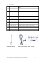
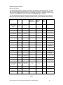
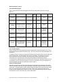
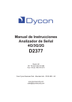
 Installation Manual
for the D48xx Series of
868MHz Wire-free
Detectors and Transmitters
Dycon Ltd
Tel: +44 (0)1443 471 060
Fax: +44 (0)1443 479 374
Cwm Cynon Business Park – Mountain Ash – CF45 4ER - UK
www.dyconsecurity.com
[email protected]
TABLE OF CONTENTS
1
2
3
3.1
3.2
3.3
3.4
3.5
3.6
3.7
Introduction
Part numbers
Wire-free detectors
D4809 Pet Tolerant PIR Wire-free PIR Detector
D4810 Wire-free PIR Detector
D4811 Door Contact / Universal Transmitter
D4812 Hand-held Controller
D4814 Smoke Detector
D4815 Water Detector
D4820 4-Channel Transmitter
D48xx Radio Detectors and Transmitters Installation Manual - D48xx-INST/09G/v2
3
4
5
9
11
13
15
16
18
19
2
Installation Manual
1.
Introduction
The D48xx range of wire-free detectors and transmitters provide PIR and door contact movement
detectors for security applications. Any other type of detection device may be wired to the Universal
Transmitter. A smoke detector and water detector are available for fire and flood warnings. A 4button hand-held transmitter allows control of systems.
All devices may be used with the D4220 2/8 channel receiver. This receiver allows any system to
incorporate wire-free detection devices, e.g. intrusion detection, fire alarms, remote lighting, remote
gate control.
The D48xx range of wire-free devices may also be used with the D3301 ADD-R as part of the D3000
range of control panels. Up to 64 wire-free devices may be used with the D3000 or D3010 control
panels. Up to 16 wire-free devices may be used with the D3020 control panel.
D4220 Receiver
D4811 Door contact /
universal transmitter
D3301 ADD-R
Receiver
D4812 Hand-held
controller
D4809 Pet-tolerant
PIR
D4814 Smoke detector
D48xx Radio Detectors and Transmitters Installation Manual - D48xx-INST/09G/v2
D4810 PIR
D4815 Water detector
3
2.
Part numbers
D3301
ADD-R
868MHz – up to 64 wire-free detectors on D300 Series control
panels
D4220
2 channel receiver
868MHz – up to 8 wire-free detectors on each of the 2 channels
(16 in total)
D4221
6 channel expander
Use with D4220 2-channel receiver. Up to 8 wire-free detectors
on each of 6 additional channels. 64 in total for a D4220 and
D4221.
D4809
Pet tolerant PIR detector
Use with ADD-R or D4220 2/8 channel receiver
D4810
PIR detector
Use with ADD-R or D4220 2/8 channel receiver
D4811
Wire-free door contact
Use with ADD-R or D4220 2/8 channel receiver
D4812
Hand-held controller
Use with ADD-R or D4220 2/8 channel receiver
D4814
Smoke detector
Use with ADD-R or D4220 2/8 channel receiver
D4815
Water detector
Use with ADD-R or D4220 2/8 channel receiver
D4820
4-channel transmitter
Use with ADD-R or D4220 2/8 channel receiver
D4830
Quarter-wave aerial
Supplied with ADD-R or D4220 2/8 channel receiver
D4831
Half-wave dipole
Use with ADD-R or D4220 2/8 channel receiver
D4832
Yagi aerial
Use with ADD-R or D4220 2/8 channel receiver
D4830 quarter wave aerial
D4831 half wave dipole aerial
D48xx Radio Detectors and Transmitters Installation Manual - D48xx-INST/09G/v2
D4832 - Yagi aerial
4
3.
Wire-free detectors
Site range survey for wire-free detectors
To ensure that the wire-free detectors can be reliably received, a range survey should be conducted
before installation. Note that radio signals cannot pass through metal sheeting, e.g. on
warehouse buildings.
Where a range survey is conducted to determine the suitability of a site, it is recommended that a test
receiver, e.g. D4220 plus a 12 volt battery and the supplied aerial be used in conjunction with a D4812
hand-held controller. Ensure that the hand-held controller is already learnt into the receiver. The
hand-held controller has got the least range of all the radio devices and, if reception can be confirmed
using this item, reliable communication with other wire-free detectors is to be expected. Reliable
received signal strength should be strength 2 or greater.
Where a range survey is conducted prior to installation, the receiver unit(s) can be placed temporarily
in the chosen location(s) and, likewise, the wire-free detectors placed temporarily in their chosen
positions. Ensure that the wire-free detectors that are to be range-tested are already learnt into the
receiver or control panel. With the receiver or control panel in the RSS display mode, press the test
buttons on the wire-free detectors or activation buttons on the portable transmitters to generate test
transmissions. Note the RSS level indication: to make sure that the transmitter will operate reliably,
the signal strength should be strength 2 or greater.
Where long-range links using directional Yagi aerial(s) are surveyed, make sure that the wire-free
detectors to be used are learnt in at short range before testing.
Care has to be taken when testing long range links using directional Yagi aerial(s) at both ends when
using the 4-channel transmitter, the position, polarity and alignment of the aerials is critical.
Range expectations
The maximum range that may be expected between a particular transmitting device and a receiver is
dependent upon several factors. These include the power of the transmitter, the type of aerials at the
transmitter and at the receiver, and the lack of obstructions between the two aerials. Refer to Table 1.
A site range survey should be conducted before any wire-free detector(s) or receiver(s) are
installed.
As a general guide, the table below gives three range indications. These are:
1. The maximum range that may be expected with the aerials 8 metres above flat ground with a
clear “line-of-sight” between the two;
2. The maximum range that may be expected with the aerials 1.5 metres above flat ground with
a clear “line-of-sight” between the two;
3. The typical range in and around normal domestic buildings.
Quarter-Wave Aerial
An 11cm-long quarter-wave aerial is supplied with the receivers and the 4-channel transmitter. This
must be positioned vertical (straight up/down). Reception will be from any direction (not directly above
or below).
Optional Dipole Aerial
The optional dipole aerial (and 5 metres of coax cable) may replace the quarter-wave aerial. The
range will be less with the dipole, typically ¾ of the range with the quarter-wave aerial. The
dipole aerial must be positioned vertical (straight up/down). The dipole should only be used in
preference to the quarter-wave when the aerial must be in a particular location and the receiver
cannot be at the same point, and a lower signal strength is acceptable. Reception will be from any
direction (not directly above or below).
D48xx Radio Detectors and Transmitters Installation Manual - D48xx-INST/09G/v2
5
Wire-Free Detectors (cont’d)
Optional Yagi Aerial
The optional Yagi aerial (and 5 metres of coax cable) may replace the quarter-wave aerial. The range
with the Yagi aerial will be approximately 2 to 3 times greater than with the quarter-wave aerial. The
Yagi aerial should only be used in preference to the quarter-wave when an increase in range or signal
strength is required and transmission or reception in one directly only is acceptable.
The Yagi aerial must be positioned vertical (straight up/down) when used with any wire-free detector
that has a vertical aerial. When the Yagi aerial is used with the 4-channel transmitter that has its own
Yagi aerial, both aerials must be both horizontal or both vertical.
Transmitter
Receiver
Receiver Aerial
Max. Range 8m
above open
ground (metres)
Max. Range
1.5m above
open ground
(metres)
Typical
range in
building
(metres)
Note
D4810 PIR Movement
Detector / D4809 Pet
Tolerant PIR Movement
Detector
D4220 or
ADD-R
Quarter-Wave
vertical aerial
1000
300
80
“
“
Vertical Dipole
700
250
50
“
“
Vertical Yagi
1500
450
120
D4811 Door contact /
universal transmitter
D4220 or
ADD-R
Quarter-Wave
vertical aerial
1000
300
80
“
“
Vertical Dipole
700
250
50
“
“
Vertical Yagi
1500
450
120
D4812 Hand-held
controller
D4220 or
ADD-R
Quarter-Wave
vertical aerial
300
200
50
“
“
Vertical Dipole
200
150
40
“
“
Vertical Yagi
450
300
70
D4814 Smoke detector
D4220 or
ADD-R
Quarter-Wave
vertical aerial
500
300
50
“
“
Vertical Dipole
350
200
40
“
“
Vertical Yagi
750
450
80
D4815 Water detector
D4220 or
ADD-R
Quarter-Wave
vertical aerial
500
300
50
“
“
Vertical Dipole
350
200
40
“
“
Yagi Aerial
750
450
80
D4820 4-channel
transmitter + Quarterwave vertical aerial or
vertical Dipole
D4220 or
ADD-R
Quarter-Wave
vertical aerial
2000
600
150
“
“
Vertical Dipole
1400
500
120
“
“
Vertical Yagi
3000
900
240
Reception from one
direction only
D4820 4-channel
transmitter + Yagi aerial
D4220 or
ADD-R
Yagi with same
polarity as Tx aerial
4000
1200
300
Point to Point only
Reception from one
direction only
Reception from one
direction only
Reception from one
direction only
Reception from one
direction only
Reception from one
direction only
Table 1
D48xx Radio Detectors and Transmitters Installation Manual - D48xx-INST/09G/v2
6
Wire-free detectors (cont’d)
Aerial Direction Patterns
Fig. 1
Fig.2
Fig. 3
Battery Life and Replacement
Battery life in all devices is dependent upon their usage. In normal domestic situations (with up to 50
activations per day), a battery life of 2 years or greater can be expected from all units. Refer to Table
2 below.
All wire-free detectors will transmit a “low battery” signal to the receiver or control panel. The voltage
at which this occurs is 1.1 volts +/- 10% per cell. This signal will be sent before the batteries are fully
discharged and the detector operation ceases. At least one month of operation may be expected after
the “low battery” signal is sent. It is important therefore to replace batteries with good quality alkaline
cells when the low battery warning is first transmitted. This is especially important for the smoke
detector.
There is a “low battery” signal transmitted by the hand-held controller. As the battery voltage falls, so
the range of operation will fall. Replace the battery in this unit when the range becomes insufficient.
Equipment is supplied without batteries. Where batteries are included they may be partially charged
and are intended for evaluation and demonstration use.
Transmitter
Battery type /
size
Number of
batteries
Replacement battery
recommendation
Battery life
expectation
D4809 Pet tolerant PIR
movement detector
AA
1
Duracell MN1500
2+ years
D4810 PIR movement detector
AA
2
Duracell MN1500
2+ years
D4811 Door contact / universal
transmitter
AAA
2
Duracell MN2400
2+ years
D4812 Hand-held controller
23A
1
Duracell MN21
3+ years
D4814 Smoke detector
AAA
4
Duracell MN2400
2+ years
D4815 Water detector
AAA
4
Duracell MN2400
2+ years
D4820 4-channel transmitter
Requires 11-15
volt supply
-
-
-
Note
Quiescent = 10mA
Active = 250mA
Table 2
D48xx Radio Detectors and Transmitters Installation Manual - D48xx-INST/09G/v2
7
Wire-free detectors (cont’d)
Transmitted Radio Signals
Table 3 below shows the radio transmissions and when they will be made for all of the wire-free
detectors.
Transmitter
Detection
Tamper
Low
Battery
Supervision
Test (Learn-in)
D4809 Pet tolerant
PIR movement
detector
Infra Red Movement =
detection. No restore signal
D4810 PIR
movement detector
Opening or
removal from wall
Yes
Yes
Test button
pressed
Sleep timer
for power
saving
Infra Red Movement =
detection. No restore signal
Opening or
removal from wall
Yes
Yes
Test button
pressed
Sleep timer
for power
saving
D4811 Door contact
/ universal
transmitter
Magnet removed = Alarm /
Magnet closed = Restore /
Loop broken = Alarm / Loop
restored = Restore
Opening or
removal from wall
or cut the Tamper
Loop
Yes
Yes
Test button
pressed
D4812 Hand-held
controller
Button A pressed / Button B
pressed / Button C pressed /
Button B pressed / No
restore signals
No
No
No
Button A pressed
/ Button B
pressed / Button
C pressed /
Button B pressed
D4814 Smoke
detector
Smoke particles detected.
Restore signal when air is
clear
No
Yes
Yes
Test button
pressed
D4815 Water
detector
Water (or other conductor)
touching detection pins. No
restore signal
No
Yes
Yes
Test button
pressed
D4820 4-channel
transmitter
Input 1 triggered / Input 2
triggered / Input 3 triggered /
Input 4 triggered / Restore
signals on all inputs
Yes
Test button 1
pressed / Test
button 2 pressed
/ Test button 3
pressed / Test
button 4 pressed
Opening or
removal from wall
Yes
Note
Table 3
Learn-in Radio Signals
All wire-free detection and transmission devices are supplied with a fixed 20 bit identity code. No two
wire-free devices will have the same identity code. This code is sent in every radio transmission from
each device.
To enable a receiver to respond to a particular transmitting device requires that the receiver learns that
device’s identity code. This is done during the “Learn-in” procedure. The receiver is put into the
Learn-in mode and a channel is selected. The relevant wire-free device then sends a Learn-in
transmission which the receiver then memorises and associates with the selected channel.
To ensure that only the transmission from the relevant wire-free device is detected and learnt, and not
a transmission from any other wire-free device, the Learn-in transmission can only be triggered by a
manually operated push button on each device. Refer to Table 3.
Supervision Radio Signals
Supervision transmissions are used to periodically test that all system wire-free devices are working
and can be received. Each wire-free device that sends a supervisory signal will transmit once every 4
to 6 minutes. The actual period is random between these two limits to ensure that supervisory signals
from 2 or more devices do not become synchronised. If there are no signals received within 20
minutes from any individual wire-free device, the receiver may output a radio fault. Where no signals
are received for 2 hours, the receiver may output a radio tamper.
D48xx Radio Detectors and Transmitters Installation Manual - D48xx-INST/09G/v2
8
3.1
D4809 Pet-tolerant Wire-free PIR Detector
Manufacture marking: IRP-9
The Pet Tolerant Passive Infra-Red Movement Detector D4809 is designed to eliminate the possibility
of false alarms due to pets (up to 27 kg).
Installation
1. Ensure that the location chosen for this item and the location(s) of the receiver(s) will provide
a sufficiently strong radio signal to be received. Refer to site range survey for wire-free
detectors (page 5).
2. Loosen the single screw on the lower end of the PIR detector and remove the back-plate.
3. Fit the batteries in their holder. The LED will flash for 30 seconds during “warm up”.
4. Fit the Test Jumper in the Test position.
5. Learn-in the PIR movement detector to the receiver or control panel by pressing the Test
button.
6. Select the mounting position so that the PIR is overlooking the required area. See Detection
Coverage below. Check operation with the LED.
7. Using that position, mount the PIR back-plate using the screws provided. This may be on a
flat surface or in a corner depending upon which case “knock-outs” are used. Where “back
tamper” detection is required, drill out the Access hole and fit a screw in the wall so that it
enters the back-plate and operates the tamper switch when the PIR detector is fitted to the
back-plate.
8. Fit the PIR detector onto its back-plate and secure with its single screw.
9. Walk test the detector to confirm the detection pattern and range.
10. When system testing is complete, open the unit and put the test jumper in the Normal position.
Identifying parts
1. Test Button aka LED indicator
It is the test button and also doubles as the LED indicator. The test button
is used for testing the radio performance and for learning purpose. The
LED indicator is used to indicate the status of system.
2. Tamper Switch
The Tamper switch protects the enclosure from being opened.
3. Battery Insulator
4. Corner mounting bracket
Learning in
Fig. 4
The PIR is learnt-in to the receiver or control panel by pressing the test button. The test button can
also be used to test the device when used with a D4220 receiver that is in the RSS display test mode.
Test jumper
Put the jumper in the test position to enable the LED and shorten the sleep time. Put this jumper in
the normal position to disable the LED and set the Sleep Time to 1 minute.
When testing is completed, the test jumper should be put in the normal position so that the battery life
is not reduced and the unit’s operation is not obvious to an observer.
D48xx Radio Detectors and Transmitters Installation Manual - D48xx-INST/09G/v2
9
D4809 Pet-tolerant Wire-free PIR Detector (cont’d)
PIR Sleep Time
“Sleep Time” will conserve power and extend the unit’s battery life. During the sleep time, radio
transmissions are inhibited. The PIR’s sleep time is set at 1 minute when the test jumper is in the
normal position. It is possible to re-trigger the sleep time and any movement that is detected during
the sleep time will extend the sleep period by one more minute. Thus continuous movement in an
area will not cause continuous radio transmissions.
PIR’s LED
In normal operation mode, the LED indicator will not light except in the following situations:
z
When the PIR is in low battery condition, the LED will light up for about 2 seconds every
time it transmits a detected movement.
z
When the cover is opened and the tamper switch is violated, the LED will light up for 2 sec.
to indicate it is transmitting the tamper signal.
z
When the tamper condition persists, the LED will light up every time it transmits a detected
movement
However, if the PIR is in test mode, the LED will light up every time a movement is detected.
Detection Coverage
The detector will cover an area 90° wide and has a range of 12 metres when fixed at 2 metres above
floor level. The unit is more sensitive to movement across its field of view than movement towards or
away from it. Mount the unit so that its field of view cannot be obstructed by shelves, curtains... Do
not mount the PIR where it is aimed at heating radiators, fires or windows.
Tamper Detection
The tamper switch and spring will detect the lid of the PIR being opened from its back-plate. To
enable the back-tamper to detect the whole unit being removed from its mountings, drill out the peg on
the back-plate that operates the tamper spring. Place a screw in the wall so that it projects into the
case through the back-plate and operates the tamper spring when the PIR lid is in place.
Radio Transmissions
The radio transmitter in the unit will send the following signals:
-
Alarm signal when the PIR detects movement (there is no Restore signal sent by this unit)
-
Tamper signal when the tamper switch is opened
-
Tamper Restore when the tamper switch is closed
-
Test signal (also used for learning-in) will be sent when the test button is pressed
-
Supervisory signal will be sent every 20 minutes
-
Low battery signal when the battery voltage falls to the low voltage threshold.
Refer to Table 3 on page 8 for transmission details.
Range Expectations
Refer to Table 1 on page 6 for range expectations.
Battery Replacement
The PIR movement detector will transmit a “low battery” signal to the control panel when the low
battery voltage threshold is reached. This signal will be sent before the batteries are fully discharged
and the detector operation ceases. Replace the 3.6V Lithium battery when the low battery warning is
first transmitted. Refer to Table 2 on page 7.
D48xx Radio Detectors and Transmitters Installation Manual - D48xx-INST/09G/v2
10
3.2 D4810 PIR Wire-free Detector
Manufacture marking: IR-8:L
Installation
1. Ensure that the location chosen for this item and the location(s) of the receiver(s) will provide
a sufficiently strong radio signal to be received. Refer to site range survey for wire-free
detectors (page 5).
2. Loosen the single screw on the lower end of the PIR detector and remove the back-plate.
3. Fit the batteries in their holder. The LED will flash for 30 seconds during “warm up”.
4. Fit the test jumper in the Test position.
5. Learn-in the PIR movement detector to the receiver or control panel by pressing the test
button.
6. Select the mounting position so that the PIR is overlooking the required area. See detection
coverage below. Check operation with the LED.
7. Using that position, mount the PIR back-plate using the screws provided. This may be on a
flat surface or in a corner depending upon which case “knock-outs” are used. Where “back
tamper” detection is required, drill out the access hole and fit a screw in the wall so that it
enters the back-plate and operates the tamper switch when the PIR detector is fitted to the
back-plate.
8. Fit the PIR detector onto its back-plate and secure with its single screw.
9. Walk test the detector to confirm the detection pattern and range.
10. When system testing is complete, open the unit and put the test jumper in the normal position.
Fig. 5
Fig. 6
Learning-In
The PIR is learnt-in to the receiver or control panel by pressing the test button. The test button can
also be used to test the device when used with a D4220 receiver that is in the RSS display test mode.
Test Jumper
Put the jumper in the test position to enable the LED and shorten the sleep time. Put this jumper in
the normal position to disable the LED and set the sleep time to 1 minute.
With the jumper in the test position, the LED will flash every time the unit transmits. This can assist
the alignment of the PIR’s pattern and range. Also, the sleep time is shortened from 1 minute to about
3 seconds. When testing is completed, the test jumper should be put in the normal position so that the
battery life is not reduced and the unit’s operation is not obvious to an observer.
D48xx Radio Detectors and Transmitters Installation Manual - D48xx-INST/09G/v2
11
D4810 PIR Wire-free Detector (cont’d)
PIR Sleep Time
“Sleep Time” will conserve power and extend the unit’s battery life. During the sleep time, radio
transmissions are inhibited. The PIR sleep time is set at 1 minute when the test jumper is in the
normal position. It is possible to re-trigger the sleep time and any movement that is detected during
the sleep time will extend the sleep period by one more minute. Thus continuous movement in an
area will not cause continuous radio transmissions.
PIR LED
There is a red LED that shines through the PIR’s white lens. This LED will indicate tamper and low
battery conditions by flashing when transmitting to alert the user that there is a problem. In addition, it
will flash with every transmission when the test jumper is in the test position.
Detection Coverage
The detector will cover an area 110° wide and has a range of 12 metres when fixed at 2 metres above
floor level. The unit is more sensitive to movement across its field of view than movement towards or
away from it. Mount the unit so that its field of view cannot be obstructed by shelves, curtains... Do
not mount the PIR where it is aimed at heating radiators, fires or windows.
Fig. 7
Fig. 8
Tamper Detection
The tamper switch and spring will detect the lid of the PIR being opened from its back-plat. To enable
the back-tamper to detect the whole unit being removed from its mountings, drill out the peg on the
back-plate that operates the tamper spring. Place a screw in the wall so that it projects into the case
through the back-plate and operates the tamper spring when the PIR lid is in place.
Radio Transmissions
The radio transmitter in the unit will send the following signals:
-
Alarm signal when the PIR detects movement (there is no Restore signal sent by this unit)
-
Tamper signal when the tamper switch is opened
-
Tamper Restore when the tamper switch is closed
-
Test signal (also used for learning-in) will be sent when the test button is pressed
-
Supervisory signal will be sent every 20 minutes
-
Low battery signal when the battery voltage falls to the low voltage threshold.
Refer to Table 3 on page 8 for transmission details.
Range Expectations
Refer to Table 1 on page 6 for range expectations.
Battery Replacement
The PIR movement detector will transmit a “low battery” signal to the control panel when the low
battery voltage threshold is reached. This signal will be sent before the batteries are fully discharged
and the detector operation ceases. Replace batteries with good quality alkaline cells when the low
battery warning is first transmitted. Refer to Table 2 on page 7.
D48xx Radio Detectors and Transmitters Installation Manual - D48xx-INST/09G/v2
12
3.3
D4811 Door Contact / Universal Transmitter
Manufacturing marking: DC-8L
Installation
1. Ensure that the location chosen for this item and the location(s) of the receiver(s) will provide
a sufficiently strong radio signal to be received. Refer to site range survey for wire-free
detectors on page 5.
2. Loosen the single screw on the end of the door contact / universal transmitter and remove the
back-plate.
3. Fit the batteries in their holder.
4. Ensure that a tamper loop and an alarm loop are correctly fitted to the terminals. See Fig. 9.
Note: when supplied, these jumpers may be fitted on one pin only or fitted vertically to two
pins.
5. Fit the test jumper in the “On” position. Fit the magnetic switch disable jumper in the “Parked”
position.
6. Learn-in the door contact / universal transmitter to the receiver or control panel by pressing
the test button.
7. Connect “normally closed” loops and switches to the “wire-in” terminals or select the mounting
position so that the magnet reliably operates the unit. Check operation with the LED.
8. Mount the transmitter back-plate and the magnet, e.g. on a door and door frame using the
screws provided or by double-sided adhesive pad. With the door closed, there should be no
more than 10mm between the magnet and the detector. Ensure that the tamper spring will
operate against the mounting surface.
9. Fit the door contact / universal transmitter onto its back-plate and secure with its single screw.
10. When system testing is complete, open the unit and put the test jumper in the “Parked”
position.
Fig. 10
Fig. 9
Fig. 11
Connection Options
Other “normally closed” detectors may be connected to the alarm loop terminals, e.g. where it is
impossible to mount the device on a door frame, it can be mounted on the wall beside the door and a
separate magnetic switch may be mounted on the door frame with its wiring connected to the alarm
loop terminals.
Learning-in
The door contact is learnt-in to the receiver or control panel by pressing the test button.
D48xx Radio Detectors and Transmitters Installation Manual - D48xx-INST/09G/v2
13
D4811 Door Contact / Universal Transmitter (cont’d)
Test Jumper
Put this jumper in the “On” position to enable the LED. Put this jumper in the “Parked” position to
disable the LED.
When the LED is enabled, it will flash every time the unit transmits. This can assist the alignment of
the door contact and its magnet, or when testing the alarm and tamper loops. When testing is
completed, the test jumper should be put in the “Parked” position so that the battery life is not reduced
and the unit’s operation is not obvious to an observer.
Magnetic Switch Disable Jumper
Put this jumper in the “On” position to disable the magnetic switch. Put this jumper in the “Parked”
position to enable the magnetic switch.
When the magnetic switch is disabled, the door contact / universal transmitter can only be operated by
the wire alarm and tamper loops.
Door Contact LED
There is a red LED on the front of the door contact. This LED will indicate tamper and low battery
conditions by flashing when transmitting to alert the user that there is a problem. In addition, it will
flash with every transmission when the test jumper is in the “On” position.
Tamper Detection
The tamper switch and spring will detect the lid of the door contact / universal transmitter being
opened from its back-plate or when the whole unit is removed from its mounting.
Radio Transmissions
The radio transmitter in the unit will send the following signals:
- Alarm signal when the magnet is moved away from the magnetic sensing area
- Restore signal when the magnet is placed against the magnetic sensing area
- Alarm signal when the alarm shorting link is opened
- Restore signal when the alarm shorting link is closed
- Tamper signal when the tamper switch is opened
- Tamper Restore signal when the tamper switch is closed
- Tamper signal when the tamper loop is opened
- Tamper Restore signal when the tamper loop is closed
- Test signal (also used for learning-in) will be sent when the test button is pressed
- Supervisory signal will be sent every 20 minutes
- Low battery signal when the battery voltage falls to the low voltage threshold
Refer to Table 3 on page 8 for transmission details.
Range Expectations
Refer to Table 1 on page 6 for range expectations.
Battery Replacement
The door contact / universal transmitter will transmit a “low battery” signal to the receiver or control
panel when the low battery voltage threshold is reached. This signal will be sent before the batteries
are fully discharged and the detector operation ceases. Replace batteries with good quality alkaline
cells when the low-battery warning is first transmitted. Refer to Table 2 on page 7.
Operation with “Normally Open” Detectors
When the door contact / universal transmitter is used with an external detector that is wired into the
terminals, then a “normally closed” contact is required, that opens to trigger an alarm. Some
applications require a detector that has a “normally open” contact.
Where the door contact / universal transmitter is used with the D3000 Series control panels, that radio
zone may be inverted. When used with the D4220 receiver, which has no Invert function, an inversion
circuit will be required between the detector and the door contact / universal transmitter. Contact
Dycon for advice.
D48xx Radio Detectors and Transmitters Installation Manual - D48xx-INST/09G/v2
14
3.4
D4812 Hand-held Controller
Manufacturing mark: RC-8L
Installation
1. The hand-held controller has the smallest internal aerial and has the shortest range of all
items in the D48xx Series of wire-free devices. Ensure that all locations from which operation
is required and the location(s) of the receiver(s) will provide a sufficiently strong radio signal to
be received. Refer to the site range survey for wire-free detectors on page 5.
2. On the rear of the unit, slide the battery cover and remove it.
3. Fit the battery in its holder.
4. Refit the battery cover.
5. Ensure that the On/Off switch is in the “On” position.
6. Press each of the 4 buttons. Check operation with the LED.
7. Learn-in the hand-held controller to the receiver or control panel by pressing each of the 4
buttons, one for each channel learnt.
8. When system testing is completed, ensure that the On/Off switch is returned to the “Off”
position.
Fig. 12 – Hand-held
controller
Learn-in
Each channel from A to D is learnt-in by pressing the associated button.
Hand-held Controller LED
There is a red LED on the front of the hand-held controller. When the On/Off switch is in the “On”
position, the LED will flash once when any of the 4 buttons are pressed.
Radio Transmissions
The unit will not operate when the On/Off switch is in the “Off” position.
The radio transmitter in the unit will send the following signals:
-
A separate alarm signal from each of its 4 buttons: A, B, C and D (there is no Restore signal
when the buttons are released)
- There is no tamper signals from this unit
- There is no supervisory signal from this unit
- There is no low battery signal from this unit
Refer to Table 3 on page 8 for transmissions details.
Range Expectations
Refer to Table 1 on page 6 for range expectations.
Battery Replacement
There is no “low battery” signal transmitted by the hand-held controller. As the battery voltage falls, so
the range of operation will fall. Replace the battery in this unit when the range becomes insufficient.
Refer to Table 2 on page 7.
D48xx Radio Detectors and Transmitters Installation Manual - D48xx-INST/09G/v2
15
3.5
D4814 Smoke Detector
Manufacture marking: SD-8L
Installation
1. Ensure that the location chosen for this item and the location(s) of the receiver(s) will provide
a sufficiently strong radio signal to be received. Refer to site range survey for wire-free
detectors on page 5.
2. Rotate anti-clockwise and remove the back-plate from the rear of the smoke detector.
3. Fit the 4 batteries in their holder.
4. Learn-in the smoke detector to the receiver or control panel by pressing the test button.
5. Select the mounting position high on a wall or suspended from a ceiling for optimum sensing
of heated (rising) air containing smoke particles. See below.
6. Mount the smoke detector back-plate using the screws provided.
7. Fit the smoke detector onto its back-plate and secure by rotating the smoke detector
clockwise.
Fig. 13 – Smoke detector
Learning-in
The smoke detector is learnt-in to the receiver or control panel by pressing the test button.
Test Button
Press the test button to test operation of the unit. When the unit is powered and operating correctly,
the LED will flash once and the siren will sound with 2 tones for one second.
Smoke Detector LED
There is a red LED on the front of the smoke detector.
The LED will flash once every 4-5 minutes, indicating that the unit is powered and operating correctly.
The LED will flash every 30 seconds when the battery voltage is low.
The LED will flash when smoke is detected.
The LED will flash once when the Test button is pressed.
Radio Transmissions
The radio transmitter in the unit will send the following signals:
-
Alarm signal 5 seconds after smoke is first detected
Alarm signal every 2 minutes throughout the period that smoke is detected (there is no
Restore signal when the smoke clears)
- Alarm signal when the test button is pressed
- Supervisory signal will be sent every 20 minutes
- Low battery signal when the battery voltage falls to the low voltage threshold
There will be no Tamper signals from this unit.
Refer to Table 3 on page 8 for transmission details.
D48xx Radio Detectors and Transmitters Installation Manual - D48xx-INST/09G/v2
16
D4814 Smoke Detector (cont’d)
Range Expectations
Refer to Table 1 on page 6 for range expectations.
Installation Requirements
To ensure that smoke in heated rising air is easily detected, the mounting position is very important.
Do install the smoke detector: at the top of a stairway;
on a flat ceiling at least 60cm from any wall
Do not install the smoke detector:
-
Where cooking smoke from a kitchen may
active it
- Close to fluorescent lighting or ventilation fans
as drafts can affect smoke detection
-
Close to ceiling beams
- Over cupboards
-
At the peak of “A frame” ceilings
Smoke Detector Siren
There is a siren built inside the smoke detector.
The siren will sound throughout the period that smoke is detected.
The siren will sound with 2 tones for one second when the test button is pressed.
The siren will sound briefly every few minutes to indicate a low battery voltage.
Silencing the Siren
When smoke is detected and the siren is activated, pressing the test button will silence it for a 10minute period. When silenced, the LED will flash once per second.
Where smoke is detected after the 10-minute period, the siren will re-activate. It may be silenced
again by pressing the test button.
Battery Replacement
The smoke detector will transmit a “low battery” signal to the receiver or control panel and the internal
siren will sound briefly every few minutes to indicate a low battery voltage. This signal will be sent
before the batteries are fully discharged and the detector operation ceases.
It is especially important to replace batteries with good quality alkaline cells when the low
battery warning is first transmitted. Refer to Table 2 on page 7.
D48xx Radio Detectors and Transmitters Installation Manual - D48xx-INST/09G/v2
17
3.6
D4815 Water Detector
Manufacture marking: WS-8L
Installation
1. Ensure that the location chosen for this item and the location(s) of the receiver(s) will provide
a sufficiently strong radio signal to be received. Refer to site range survey for wire-free
detectors on page 3.
2. Remove the two screws on the cover of the water detector and remove the cover.
3. Fit the 4 batteries in their holder.
4. Learn-in the water detector to the receiver or control panel by pressing the test button.
5. Select the mounting position so that the unit is well above the highest water level expected.
Mount the unit’s back-plate using the screws provided.
6. Ensure that the water-resistant seal is correctly located in its channel on the back-plate. Fit
the water detector onto its back-plate and secure with the two screws.
7. Using the clip provided, mount the “2-pin” water sensor at the level where a rising water level
will transmit the signal.
Fig. 14 – Water Detector
Learning-In
The water detector is learnt-in to the receiver or control panel by pressing the Test button.
Radio Transmissions
The radio transmitter in the unit will send the following signals:
-
Alarm signal when water or other conductor “bridges its detection pins (there is no restore
signal when the detection pins become clear)
-
Alarm signal when the test button is pressed
-
Supervisory signal will be sent every 20 minutes
-
Low battery signal when the battery voltage falls to the low voltage threshold
There will be no tamper signals from this unit.
Refer to Table 3 on page 8 for transmission details.
Range Expectations
Refer to Table 1 on page 6 for range expectations.
Battery Replacement
The water detector will transmit a “low battery” signal to the receiver or control panel when the low
battery voltage threshold is reached. This signal will be sent before the batteries are fully discharged
and the detector operation ceases. Replace batteries with good quality alkaline cells when the low
battery warning is first transmitted. Refer to Table 2 on page 7.
D48xx Radio Detectors and Transmitters Installation Manual - D48xx-INST/09G/v2
18
3.7
D4820 Long Range 4-Channel Transmitter
A 4-channel transmitter case measures 168 x 108 x 35mm (h x w x d). When used with the quarterwave aerial that extends from the case, the overall size is 250 x 108 x 35mm (h x w x d).
The case mounts directly onto a wall or any surface using any of the multiple mounting holes in the
rear of the case. There are multiple cable entry points on the rear of the case and cable knock-outs on
the top, bottom and sides of the case. See Fig. 14.
Installation
1. Ensure that the location chosen for this item and the location(s) of the receiver(s) will provide
a sufficiently strong radio signal to be received. Refer to site range survey for wire-free
detectors on page 5.
2. Remove the two screws from the front of the 4-channel transmitter case and remove the lid.
3. Remove the securing screw from the centre of the circuit board and then unclip the circuit
board by releasing the two white plastic catches. Remove the circuit board from the case.
See Fig. 15.
4. Mark the position of the selected case mounting holes. Drill the wall. Break out the selected
cable entry point(s), then mount the case. When used with the quarter-wave aerial, ensure
that the aerial is vertical (straight up or down). The break-outs on the ends of the case may
be opened by inserting a terminal screwdriver into the slot at the end of the knock-out and
twisting.
5. Re-install the circuit board in the case. Replace the securing screw.
6. Connect the aerial to the aerial socket. The aerial must be vertical.
7. Connect the DC supply to the power terminals (11-15 volts). Where cables have been
brought into the case, the outer sleeving of cables should be removed where they enter the
case. Always tie-wrap cables to the cable guides before connecting them to the terminals.
Ensure that any wiring is lead away from the circuit board and the aerial. With wiring close
(10cm) to the aerial, a reduction in radio range should be expected.
8. Connect “normally closed” loops and switches to each of the Z1 to Z4 input terminals. Check
operation with the LED.
9. Where external tamper detection is required, connect the “normally closed” loop to the A/T
tamper terminals. When unused, link terminals together. Adjust the back tamper screw for
correct operation. See Fig. 16.
10. Learn-in each channel of the 4-channel transmitter to the receiver or control panel by pressing
the test button for that channel.
11. When system testing is completed, refit the case lid. Ensure that no wires are trapped
between the back and lid, or trapped around the tamper switch. Refit the 2 lid-securing
screws.
NOTE: the lid will fit either way round but the screws will only fit with the lid the correct way
round. Do not use longer screws than those provided when securing the lid to avoid damage
to the case.
D48xx Radio Detectors and Transmitters Installation Manual - D48xx-INST/09G/v2
19
D4820 Long Range 4-Channel Transmitter (cont’d)
Fig. 15 – Long-range
4-channel transmitter
Tamper Switches
The case includes 2 tamper switches. The one with a spring
fitted is a “lid tamper” switch only. The case “back tamper”
switch is operated by an activation lever moulded into the
rear of the case. This lever holds the switch in its closed
position. See Fig. 16.
To adjust, loosen the case mounting screws, then turn the
“back tamper” screw further into or out of the wall until it
operates the back tamper switch. Press the case onto the
wall, then release it to hear the click from the “back tamper”
switch. Re-tighten the case mounting screws.
Aerial Options
The 4-channel transmitter may be used with the supplied D4830 quarter-wave aerial, the optional
D4831 dipole aerial and 5m coax lead, or the optional D4832 Yagi aerial and 5m coax lead.
Power Requirement
The 4-channel transmitter requires a supply voltage of between 11 and 15 volts. This will be typically
13.6 volts when used with intruder alarm control panels. The current requirement is 10mA quiescent
but this rises to 250mA for the period that the unit is transmitting (typically 0.75 seconds).
D48xx Radio Detectors and Transmitters Installation Manual - D48xx-INST/09G/v2
20
D4820 Long Range 4-Channel Transmitter (cont’d)
Anti-Clash Jumper
Putting this jumper in the position furthest from the screw terminals enables the “anti-clash”
transmissions. Put this jumper in the position nearest the screw terminals to disable “anti-clash”
transmissions. “Anti-clash” transmissions will ensure that transmissions from other systems do not
clash with this 4-channel transmitter, which could result in lost signals.
When anti-clash is disabled, each triggering event will result in one transmission of approx. 750mS.
When anti-clash is selected, each transmission will be repeated 3 times, spaced by a random interval
of 1 to 5 seconds.
Fig. 17 - 4-channel transmitter circuit board
Input Connections
Each of the 4 channels is triggered by breaking an electrical connection between its input terminals
(marked Z1 to Z4). This is most easily arranged by a “normally closed” switch or relay contact. When
the electrical connection between each channel’s input terminals is re-established, a restore
transmission will be sent.
LED Indicator
There is a red LED on the unit. This LED will be on whenever the 4-channel transmitter is sending a
signal.
Learning-In
Each channel of the 4-channel transmitter is learnt-in to the receiver or control panel by pressing the
test button for that channel.
Tamper Detection
The tamper switches and spring will detect the lid of the 4-channel transmitter being opened from its
back-plate or when the whole unit is removed from its mounting.
Tamper Detection (cont’d)
An external “normally closed” loop and/or switch(es) may be connected to the anti tamper terminals.
When this is unused, a link must be placed across these terminals.
D48xx Radio Detectors and Transmitters Installation Manual - D48xx-INST/09G/v2
21
D4820 Long Range 4-Channel Transmitter (cont’d)
Radio Transmissions
The radio transmitter in the unit will send the following signals for each channel:
-
Alarm signal when the input loop on that channel’s input terminals is opened
-
Restore signal when the input loop on that channel’s input terminals is closed
-
Test signal (also used for learning-In) will be sent when the test button is pressed.
The radio transmitter in the unit will send the following signals:
-
Tamper signal when either or both tamper switches are opened
-
Tamper Restore signal when both tamper switches are closed
-
Tamper signal when the anti-tamper loop on the anti-tamper terminals is opened
-
Tamper Restore signal when the anti-tamper loop on the anti-tamper terminals is closed
-
Supervisory signal will be sent every 20 minutes
-
Low battery signal when the supply voltage falls to the low voltage threshold
Refer to Table 1 on page 6 for transmission details.
Range Expectations
Refer to Table 3 on page 8 for range expectations.
Supply Voltage Monitoring
The 4-channel transmitter will transmit a “low battery” signal to the receiver or control panel when the
supply voltage threshold is reached (9.5v +/- 0.5v).
D48xx Radio Detectors and Transmitters Installation Manual - D48xx-INST/09G/v2
22