1
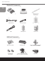
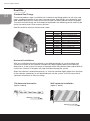
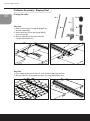
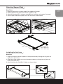
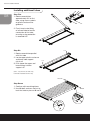
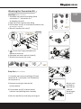
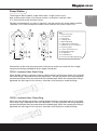
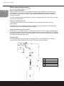
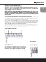
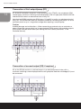
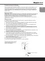
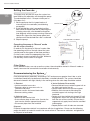
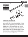
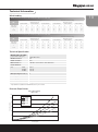
Re n ewa b l es
Installation Manual
Varisol Installation Manual
Contents
Introduction
Using this guide
Kit components
Important pre-installation information
1
1
2
3
Roof kits
Overview
Roof Kit Sizing
4
5
Collector Assembly
Sloping Roof assembly
Installing Tubes
Attaching the connection kit
6
7
9
Pump station
Safety vessel connections
Wiring the control panel
11
12
13
Commissioning the system
Decommissioning the system
Recycling Information
15
16
17
Servicing and maintenance
18
Technical Information
Wind loading
Technical Specification
Pressure drop curves
19
19
19
Warranty Statement
20
Maintenance Schedule Form
21
Introduction
Solar hot water systems should be designed and sized correctly before commencing the
installation. Proper design will ensure that a system is correctly sized to provide many years
of optimised performance and most or all of the required hot water when the most solar
radiation is available. However a supplementary heating system such as oil or gas boiler,
heat pump or wood boiler is required for months which have less solar radiation.
For large systems, Kingspan provide a system design service to its Accredited Installer
Network and technical design consultants. Please visit www.kingspansolar.com to locate an
Accredited Installer or distributor in your area.
This guide will illustrate and explain how a system should be installed to conform with the
Kingspan Renewables manufacturer guidelines for the Varisol Collector.
Using this guide
Stages of a solar installation are described in the following pages, with illustrations
where necessary to explain how to install the relevant components, and contains general
recommendations and important safety information.
Handling Guidance
• Tube boxes should be transported horizontally.
• Heavy goods should not be loaded on top of the kit boxes.
• Care should be taken when opening boxes to prevent scratches or sudden
shocks to the glass.
• Do not use sharp objects to open the tube boxes.
Installation Guidance
• Unpack and install tubes only after the roof kit and pipe work has been installed.
• Do not leave the solar collector exposed to solar radiation when the solar loop and
collector have been drained. Collectors left exposed in a dry state must be covered to
prevent possible long term damage.
• The dark blue side of the copper within the tube is the active surface.
• A heat dissipation loop (heat dump) is recommended
• The pipework of the solar collector loop is to be earthed and the collector is to be lightning
protected in accordance to local regulations.
For further technical support please contact the following numbers,
Ireland - 1800 812 718 or UK – 0845 812 0007.
Health and Safety Precautions
A solar panel installation must be performed in accordance with all Health & Safety legislation
and local building/planning regulations for the relevant jurisdiction.
Furthermore, the necessary electrical work required to install control equipment should be
undertaken by a qualified electrical contractor.
01
Varisol Installation Manual
Standard Kit Components
02
Dual Stream Pump Station
SC100 Controller
Sloping Roof Kit
with Brackets
Connection Kit
Flexi Connections
Expansion Vessel
Tubes
Cooling Vessel
Tyfocor® LS
Additional Components
Solar Roof Flashing
Installation tool
22mm Thermostatic Mixing Valve
Note - 28mm also available
Insulated Hose
Mounting Set
22mm 3 Port Diverter Valve
Note - 15 & 28mm also available
Stubfitting
Important Pre Installation Information
Sizing of safety equipment
Expansion vessel sizes are relative to the volume of liquid in the system. Therefore it is
important that the Thermomax ‘Technical Design Guide’ is consulted for each system.
Pipe Sizing (minimum of 15mm diameter pipework must be used)
Pressure Drop - Tyfocor LS
Collector
Area
m2
Pressure
Drop
mbar
Pipe External
Diameter
mm
Flow Rate
Ltr/hr
1
60
15
2
2
120
15
3.5
3
180
15
10
4
240
15
21
5
300
22
35*
6
360
22
53
7
420
22
80*
8
480
22
110*
9
540
22
153
* figures marked as such are estimates based on other measurements
Expansion Vessel Sizing
Collector
Area
m2
System Volume
Ltr
Static Height
m
Expansion
Vessel Size
Ltr
Cooling
Vessel Size
Ltr
1
18.9
5
18
5
2
20.8
5
18
5
3
22.7
5
25
8
4
24.6
5
25
8
5
26.5
5
35
12
6
28.4
5
35
12
7
30.3
5
35
12
8
32.2
5
50
18
9
34.1
5
50
18
When selecting a vessel for intermediate sizes, the vessel should be selected by rounding area up to nearest m².
All sizes above are calculated based on a 17ltr system volume as an example. For larger volumes the expansion
vessel size should be recalculated. Cooling vessel sizes are dependant on pipe dimensions and can be calculated
on a case by case basis or selected using the table above as a guideline.
Cooling Vessel
It is strongly recommended that a cooling vessel is used with the collector to protect the
expansion vessel from stagnation temperatures.
03
Varisol Installation Manual
Roof Kits
Standard Roof Fixings
The Varisol product range is available with a choice of roof fixing options to suit many roof
types, see diagram below for the most common fixings. Roof fixings are available for slate,
tiled, double lap plain clay, metal seam and concrete. For others please contact Kingspan.
The most common fixings are illustrated and explained in the following section and may be
easily secured to slate, tile or masonry finishes.
Roof kits and their relevant manufacturer codes:
Option
1
1
Code
KSK0039
KSK0040
KSK0041
KSK0062
KSK0063
KSK0064
KSK0042
KSK0043
KSK0044
KSK0065
KSK0066
KSK0067
3
4
2
2
3, 4 and 5
5
Description
Varisol 10 Sloping Roof Kit
Varisol 20 Sloping Roof Kit
Varisol 30 Sloping Roof Kit
Varisol 10 Bolt Down Roof Kit
Varisol 20 Bolt Down Roof Kit
Varisol 30 Bolt Down Roof Kit
Varisol 10 A Frame Kit
Varisol 20 A Frame Kit
Varisol 30 A Frame Kit
Varisol 10 Façade Kit
Varisol 20 Façade Kit
Varisol 30 Façade Kit
Horizontal Installations
With any installation where the collector is installed horizontally on a wall façade or roof
surface; the airvent on the collector manifold must be the highest point of the collector,
otherwise air in the system will remain in the pipes within the collector tubes and be difficult
to flush out. Airlocks in the pipes will stop circulation through the system.
When the collector is orientated correctly, i.e. with the manifold slightly higher than the base
of the collector, (see below) air will be forced back into the system. In this instance the air
separator will prevent air from circulating.
Flat horizontal orientation
Wall horizontal installation
(option 4 above)
(option 5 above)
2° Min
Minimum 2˚ angle
2° Min
04
Minimum 2˚ angle
Roof Kit Sizing
The modular design of the Varisol collector means that any number of tubes can be
assembled to make up the required collector size. Since the mounting kit cross rails are
only supplied in 10, 20 and 30 tube sizes it is necessary to cut the rails to length if an
intermediate sized collector is required. The table below gives the required length of rail for
each given size. Burrs and sharp edges should be removed.
Collector
Area
m²
Number of
tubes
0.1
0.2
0.3
0.4
0.5
0.6
0.7
0.8
0.9
1
1.1
1.2
1.3
1.4
1.5
1.6
1.7
1.8
1.9
2
2.1
2.2
2.3
2.4
2.5
2.6
2.7
2.8
2.9
3
1
2
3
4
5
6
7
8
9
10
11
12
13
14
15
16
17
18
19
20
21
22
23
24
25
26
27
28
29
30
Kit Type
10 Tube Rail
712mm
20 Tube Rail
1423mm
30 Tube Rail
2135mm
Required Support
Rail Length
mm
Side Rail
Separation
mm
71
142
214
285
356
427
498
569
640
712
783
854
926
997
1068
1139
1210
1281
1352
1423
1494
1565
1637
1708
1779
1850
1921
1992
2063
2135
350-450
350-550
500-600
500-600
500-600
500-700
500-700
600-800
600-900
600-900
600-1000
600-1000
600-1100
700-1200
700-1200
700-1200
700-1200
700-1200
800-1300
800-1300
800-1400
800-1400
800-1400
Examples:
• To make an 18 tube collector simply take a 20-way rail and cut to 1281mm.
• To make a 44 tube collector join a standard 20-way rail to a 24-way, the 24-way being
made by cutting a 30-way rail to 1708mm.
• In the case of a sloping roof mounted collector, the available rafter spacing should be
considered when sizing the collector to ensure that an appropriate side rail spacing can
be achieved.
05
Varisol Installation Manual
Collector Assembly - Sloping Roof
06
Fixing the rails
D x10
A x2
C x4
Step One
1. Refer to mounting kit sizing on page 5 for
bracket seperation
2. Attach brackets (C) to roof using M8x50
coachscrews (E)
3. Secure side rails (A) to lower brackets
using M10x65 bolt assy
E x8
B x2
G x4
F x4
A
E
C
F
x4
x2
Step Two
1. From upper end of each side rail, slide 2 M8x16 bolt into position
2. Secure side rails (A) to upper brackets (C) using M8x20 bolt assy
D
x2
Attaching Support Rails
Step Three
1. Refer to mounting kit sizing on page 5 for support rail lengths
2. Slide 2 M8 bolts into lower face of each support rail (B)
3. Attach 90° bracket (G) in 4 places using M8 nuts & washers at locations illustrated
4. Attach upper and lower support rail to 90° bracket as shown below
07
B
G
D
1500mm
100mm
x4
1400 – 1700mm
400 – 600mm (10)
600 – 1000mm (20)
800 – 1400mm (30)
Installing the first tube
Step Four
1. Align first tube with end of support rail and push home by clicking into rail (push on
upper push point only)
2. Align lower tube support clip into rail and push home by clicking into rail (push on
lower push point only)
3. Attach tube to rail using MB x 20 bolts as shown below.
Varisol Installation Manual
Installing additional tubes
08
50˚
2
Step Five
1. Rotate second tube
approximately 50° to first
tube, using arrow symbols
on plastic enclosure for
guidance
1
2. Firmly insert male fitting
of second tube to female
connection of first tube,
ensuring o-ring protection
is removed first.
Step Six
1. Rotate second tube parallel
with first tube
2. Locate upper plastic enclosure
and lower tube support
clip in rail
3. Push home the upper and
lower fittings into the
support rail
PUSH
PUSH
(Note - only the first, last and every
tenth tube need bolted to the rail)
RETURN
Step Seven
1. Continue with remaining tubes.
2. Use M8 bolt, washers and nut to
lock final tube in place at X and Y
X
Y
FLOW
Attaching the Connection Kit
09
Step Eight (return connection)
1. Assemble and connect end fittings (Male
connection A, T connection G &
Air bleeding valvue E)
2. Open lid on left hand end tube fitting
3. Place rubber seal (D) on male end of collector area
A
B
C
D
E
F
G
H
I
(blocking upper chamber)
4. Secure in position with clip (F)
Qty. Tubes
A
F
I
E
D
G
5.
Ensure clip (F) legs protrude out of
bottom of enclosure
6. Complete and attach technical label (I)
7. Close lid and secure with screw
A
B
C
D
E
F
G
H
I
C
Step Nine (flow connection)
1. Assemble and connect end fittings (Female
connection B, T connection G & Temperature
sensor pocket H)
B
G
2. Remove securing pin from female
end of collector
3. Place rubber seal (C) in female end of
collector area (blocking lower chamber)
4. Secure in position by relocating securing pin
H
Sensor must
be fitted on
flow side of
collector.
See diagram
for step 7
Varisol Installation Manual
Connection Information
10
In any solar panel system, the ‘return’ refers to the intake in the collector where liquid
is returning to be reheated. The ‘flow’ refers to the collector side where the liquid is
flowing to the heat exchanger.
Note: It is essential that the collector temperature sensor is located in the flow
of the collector.
The following illustrations shows the connections to the manifold.
Types of Connections
The only pipes which should be used with a solar installation are copper pipe, continuous
flexible stainless steel or mild steel.
When using copper pipe, only compression or brazed joints can be used. Solder and
galvanised fittings will not withstand high temperature or expansion and are therefore not
suitable for solar pipe work.
PEX / PLASTIC / PEX-ALU-PEX or GALVANISED TUBING OR FITTINGS
SHOULD NOT BE USED UNDER ANY CIRCUMSTANCES
Flexible Pipe Connections
Flexible pipe connections are recommended to connect the manifold through the building
fabric and allow flexibility in connecting to the internal pipe work.
Flexible stainless steel pipes are available in both a 15mm and 22mm diameter. If
connecting one diameter pipe to another, a suitable reducer compression fitting is
recommended to make the connection.
Insulation
All pipe work on the solar loop should be insulated with high temperature insulation (such
as HT/Armaflex from Armacell GmbH). High temperature insulation is essential as standard
pipe insulation will melt at temperatures experienced by solar pipes.
The wall thickness of the insulation should be equal to the diameter of the pipe. The only
pipes which should not be insulated are the pipes to the safety vessels as they should
allow heat to dissipate when the system is experiencing excessive heat and pressure.
System Pressure
The recommended system pressure is 1 bar + 0.1 bar / 1m static height
Pump Station
The Kingspan Solar product range offers both a single stream and a
dual stream pump station. Each pump station is available in two flow rates,
2-12 litres/minute and 8-28 litres/minute.
The flow rate required on a system is typically 1 litre per minute, per square metre installed.
Therefore a 2-12 litre/minute pump station will be sufficient for systems up to 12m².
9
6
6
9
13
10
8
7
7
5
11
13
10
8
5
12
4
12
2
3
4
2
3
1
9
1
Key
1
2
3
4
5
6
7
8
9
10
11
12
13
Drain connection
Fill connection
Flow meter
Isolating valve
Motorised pump
6 bar pressure relief valve
Expansion vessel connection
Pressure guage
22mm connections (x 4)
Temperature guage
Air separator
Insulated fascia
Pressure relief discharge point
9
Connections of flow and return pipe work to the pump station are made with the straight
compression fittings provided for direct copper connection.
C0784 – Insulated Hose Stub Fitting
When flexible stainless steel pipe is being used to connect to the pump station, the insulated
hose stub fitting is required to make the connection. The split ring within the fitting should be
removed and placed over the second rib of the flexible pipe. When the compression fitting is
tightened, the split ring will click twice as it positions itself and locks inside the fitting.
C0785 – Insulated Hose Clamp Ring
When the short flexible connection is being joined to stainless steel pipe work, the insulated
hose clamp ring is required to make the connection. The split ring within the fitting should be
removed and placed over the second rib of the flexible pipe. When the compression fitting is
tightened, the split ring will click twice as it positions itself and locks inside the fitting.
11
Varisol Installation Manual
Safety Vessel Connections
12
Pressure Relief Valve (PRV)
Rated at 6 bar, the PRV may discharge heat transfer fluid (Tyfocor® LS) which must be
channelled into a container capable of withstanding high temperature discharge and
containing the total collector volume. The container should be secured so it cannot be
removed or spilled.
The PRV should not be channelled into a drain or any pipe work which will allow it to enter
the normal water course.
Fitting the expansion vessel:
The expansion vessel must be located below the level of the connection from the
pump station.
The expansion vessel supplied includes an appropriate corrugated hose and threaded
connection to join the vessel to the pump station.
Temperature Reducing Vessel (TRV)
Also known as a ‘cooling vessel’ or ‘stratification vessel’, the TRV is highly recommended.
Due to high temperatures which can be experienced within the solar loop, the TRV reduces
the temperature of the heat transfer fluid before it enters the expansion vessel and extends
the lifetime of the expansion vessel.
Fitting the TRV:
With the direct flow vessel kit, which includes the TRV, a corrugated hose assembly is
included to join the expansion vessel to the TRV from the pump station.
1
6
2
TRV
4
3
2
5
1
2
3
4
5
6
PRV discharge point
Wall bracket (supplied)
Discharge container
TRV kit
Expansion vessel
Dual stream pump station
Wiring the Solar Control Panel
All electrical aspects of the installation should be undertaken by a qualified electrician.
Note that for safety, the pump and sensor connections should always be wired prior to
connecting power to the solar control panel.
IMPORTANT: The solar control panel must have a permanent electrical power
supply which must not be interrupted either manually or with a time switch. If the
permanent electrical supply to the building is to be switched off for any period of
time, the solar collector(s) should either be covered, or the system drained and the
tubes removed.
In order to protect the normal operation of the control panel, it should be located at least
100 mm from insulated pipes which may become hot during operation.
Control panels use PT1000 sensors containing twin core copper cable with a 0.75mm
cross section. The sensors supplied are 1.5 metres in length.
Sensor cables can be extended with twin core copper cable of 0.75mm diameter up to
50 metres and 1.50mm diameter between 50-100m. Screened cable should be used on
the sensor cables to prevent RFI from electrical cables. All connections to extend the
cables should be housed in a junction box for protection.
The following diagrams show the connection of the solar pump and other relays on the
SC range of controllers. This should be read in conjunction with the Installation and
Operation Manual supplied with each SC control panel.
Power Supply Connection:
Input connection
for 1-4 sensors:
Sensor Connection
The connection of PT1000 sensors is as shown on the
right. The polarity of the sensor cables is not relevant on
each sensor. The SC100 has four inputs as illustrated
below. However the SC200 and SC300 can receive five
and six sensors respectively (for larger system design)
and are connected in the same way.
13
Varisol Installation Manual
Connection of first output/pump (R1)
14
R1 of the SC controllers comprises a semiconductor relay (TRIAC), also suitable for RPM
control with a maximum switching current displayed on the unit type plate. Both the SC100
and the SC200 contain an electromechanical relay, R2.
Note that the SC300 contains two RPM relays, R1 and R2 as well as an electromechanical
relay, R3. The SC200 and SC300 are therefore suitable for controlling two pumps i.e. for an
east/west panel array or a stagnation configuration requiring a second pump.
Caution
Avoiding damage and malfunctions – When connecting an external relay or contactor, or
when connecting a pump which has its own electronic RPM control, the controller output’s
RPM control must be deactivated (see “Setting the RPM control parameters” in the
Controller Manual).
Connection of second output (R2) if required
R2 on the SC100 contains a switched output via an electromechanical relay with a
maximum switching current displayed on the unit type plate. Note the wire bridge (D1) must
be connected.
Commissioning the System
The evacuated tubes should be installed at a time when there is very low light such as
late afternoon when the sun is low and not particularly strong. Alternatively the tubes
should be covered. This is important as tube connections can heat up considerably in
a short space of time and have potential to cause injury even if the glass temperature
remains cool.
Expansion Vessel
IMPORTANT: Prior to filling the system, the expansion vessel pressure must be set
0.3 Bar below the system pressure. Omitting to perform this check will result in
irregular pressure readings during the commissioning of the system.
The pressure is checked at the base of the vessel and the bleed valve may be bled or
topped up with a pump.
Filling the Loop
It is important that a motorised flush and fill centre is used to fill and pressurise the
system with Tyfocor® LS as follows:
1. Open the fill and drain valves to allow the liquid to circulate around the solar loop
2. Turn the hot and cold temperature gauges 45˚ clockwise.
3. Close the isolating valve above the flow meter to ensure all air and liquid passes
through the fill centre to filter any air and contaminants.
4. Run the fill centre pump to circulate the Tyfocor® LS for approximately 20 minutes.
5. Open and close the isolating valve intermittently to circulate air bubbles which may
accumulate in the sight glass.
6. Return isolating valve to closed position.
7. When the solar loop has been purged of air, close the bottom/drain connection – the
fill centre will begin to pressurise the solar loop.
8. Reopen the isolating valve above the flow meter fully.
9. Fill the loop until the pressure gauge just exceeds the required pressure, stop the
pump and immediately close the fill connection. Check pipe joints on the solar loop
for leaks and check that pressure is not lost over a 30 minute period.
10. If all the plumbing is sound, set the system pressure by opening the return connection
until the required pressure is met.
11. Return the temperature gauges to the original position.
12. The fill centre may now be disconnected.
13. Cap the fill and drain points with the brass covers provided.
The pipes from the flush and fill
centre should be connected as
shown in the diagram:
FILL
DRAIN
FLUSH AND FILL CENTRE
15
Varisol Installation Manual
Setting the flow rate
16
The pump may only be run when the system has
been filled as dry operation will damage the pump.
The desired flow rate is 1 litre per minute per m²
(10 tubes=1m²).
1. Set the pump to the first speed and run it
manually from the controller (see following
paragraph).
2. If the desired flow rate is exceeded, set the
flow meter to the desired rate by adjusting the
isolating valve with a flat headed screwdriver
(see diagram) with the pump running. Otherwise
repeat this step at the next pump speed and
continue until the desired flow rate is achieved
3. Stop the pump.
OPEN CLOSED
ISOLATING VALVE
Left side view of controller
Operating the pump in ‘Manual’ mode
(for SC range controllers)
In order to run the pump in ‘Manual’ mode, slide
the operating switch on the left side of the solar
control panel to the upper of the three positions.
On the screen, select the appropriate relay with
the up/down arrows and press the ‘Set’ button to
run the relay and to switch it off again.
Other Relays
If any additional relays are set up on the system, these should be tested in ‘Manual’ mode as
above, to ensure the connections have been wired correctly.
Decommissioning the System
Due to temperatures potentially exceeding 170˚C and pressures greater than 6 bar, a solar
installation should only be decommissioned by a trained individual. The system should be
decommissioned in low light, ideally in the morning when the solar loop should be coolest.
1. Electrical
• Isolate controller from mains
• Remove cables to consumer units i.e.
controller and pump
• Remove sensors and associated cables
• Remove earthing cables
2. Collector Loop
• Beware of hot transfer fluid
• Drain collector loop at drain valve. Contain the
heat transfer fluid for appropriate disposal.
• Disconnect pipes from the manifold
3. Varisol Collector Disassembly
• Remove M8 bolt from manifold support rail on
the right hand end of the rail.
• Unclip rubber retainer on the tube support
• Slide the Varisol removal slide along the
manifold support rail strating at the right
hand end.
• Rotate each tube individually through 50˚ until
engagement arrows line up and pull one tube
from the rest of the assembly. Ensure tube is
supported; only apply force onto the manifold
to disengage.
• Repeat process until all tubes are removed.
Disposal
Dispose of separate materials in accordance with local regulations. Please see the following
pages for details of materials used in the construction of Thermomax collectors and guidance
on disposal of antifreeze.
Recycling Information
on
Item No.
1
2
3
4
5
6
7
8
9
10
Material
Aluminium
EPDM Rubber
Bronze
PA66 30%GF
PA66 Natural
Stainless Steel
Copper
Glass
Brass
PPS
17
1
6
2
6
4
5
1
9
6
2
2
10
9
2
6
7
2
3
4
7
8
Disposal of Solar Anti-Freeze Solution
The solution we supply with our solar systems is a thermal transfer fluid based on 1,2
propylene glycol and water. The solution also contains corrosion inhibitors and has been
specifically designed for used in solar systems with elevated temperatures, such as those
experienced with Vacuum Tube Collectors.
Propylene Glycol is a widely used ingredient in pharmaceutical, food, cosmetic, personal
care, flavours and animal feed applications. Propylene glycol is not volatile, but is
miscible with water. Propylene glycol is not harmful to aquatic organisms and is readily
biodegradable; however the disposal of the solution should be done in a responsible
manner taking into consideration local Environmental and Health & Safety legislation.
While the solution is not subject to registration as a hazardous material according to EEC
directives the solution should be disposed of by special means. There are a number of
specialist companies that can deal with the disposal of propylene glycol. A list of these
companies is available upon request. A copy of the EEC Safety Data sheet and Technical
Information sheet is available upon request. We recommend that you contact your local
authority to check that they will accept the solution at special landfill collection points.
There are a number of specialist companies that can deal with the disposal of propylene
glycol, a list is available on request: [email protected]
Varisol Installation Manual
Servicing and Maintenance
18
Users should regularly check the temperatures which the solar control panel is
recording. With the SC range of controllers, simply pressing the ‘SET’ button on the
fascia once will display the upper and lower collector temperatures since the control
panel was last reset. If the collector temperatures have been excessively high i.e. over
170˚C, it is recommended that the antifreeze level checked using a refractometer by a
qualified engineer.
A sample of the Tyfocor® LS antifreeze fluid can be extracted from the pump station at
the pump itself. The large centre of the pump hub can be opened with a large flathead
screwdriver. This should be opened slowly until a few drops of the antifreeze fluid are
released. A sample of the fluid placed on the glass of the refractometer will display the
level of antifreeze in the system. If the antifreeze has lost its antifreeze properties the
system should be refilled with fresh Tyfocor® LS.
It is recommended that the solar system is serviced annually by a qualified engineer and
immediately if the system shows evidence of having lost pressure or has discharged
liquid at the pressure relief valve. The Tyfocor® LS antifreeze fluid should always be
replaced after 7 years.
Maintenance schedule
A qualified person should service the system at the recommended intervals, using the
maintenance schedule. In addition the user should check the system pressure at regular
intervals. A visual inspection of the pressure gauge is required to check that the system
pressure is maintained at the level noted over.
Please see page 21 for maintenance schedule form.
Technical Information
Wind Loading
19
Stress and maximum load on the substance on flat roofs to DIN 1055
Prevention of Collector Slippage
25°
Prevention of Collector Lifting
Weight Per Foot (kg)
Weight Per Foot (kg)
10 Tube Collector
Height Above
Ground (m)
A
20 Tube Collector
B
30 Tube Collector
10 Tube Collector
A
B
A
B
A
B
20 Tube Collector
A
B
30 Tube Collector
A
B
8
76
102
76
102
116
155
26
65
26
65
41
100
8 to 20
129
178
129
178
195
269
57
125
51
125
80
191
Stress and maximum load on the substance on flat roofs to DIN 1055
Prevention of Collector Slippage
45°
Prevention of Collector Lifting
Weight Per Foot (kg)
Weight Per Foot (kg)
10 Tube Collector
20 Tube Collector
30 Tube Collector
10 Tube Collector
30 Tube Collector
A
B
A
B
A
B
A
B
A
B
A
B
8
102
171
102
171
156
256
73
73
73
73
111
111
8 to 20
177
287
177
287
266
430
137
137
137
137
206
206
Technical Specification
Dimensions per tube
(Length x Width x Height) [mm]
1950 x 70.9 x 70.9
Weight per tube (kg)
2.2
Volume per tube (l)
0.19
Max. Field Size (m²)
150 Tubes = 21m² (Gross) / 15m² (Apperture)
Cu Pipe Diameter 1-3m²
15 x 1
(mm)*
4-9m²
22 x 1
10-15m²
28 x 1.2
16-20m²
35 x 1.5
Max. Operating Pressure (bar)
6
Min. Slope (°)
0
Max. Slope (°)
90
Max. Load (kN/m²) (DIN 1055-5)
2.5
Heat Transfer Medium
Propylene Glycol suitable for evacuated tube collectors
* Pipe diameters calculated for 0.1l/min/tube and v_max = 0.5m/s
Pressure Drop Curves
Varisol Pressure Drop
(Tyfocor LS)
120
90-way
100
60-way
40-way
Pressure Drop (mbar)
20 Tube Collector
Height Above
Ground (m)
30-way
80
20-way
60
40
20
0
0
50
100
150
200
250
Flow Rate (ltr/hr)
300
350
400
450
500
Varisol Installation Manual
Warranty Statement
20
Kingspan Renewables Ltd. Warranty Statement for Solar Goods
Subject to the following provisions, Kingspan Renewables warrants that the Goods will be free from defects
in material and workmanship for a period of 20 years in relation to VACUUM TUBES and a period of 5
years for VARISOL FLOW CONDUITS & COVERS, MANIFOLDS and KITS from their date of manufacture.
“RESTRICTED PRODUCTS” are limited to a period of 12 months warranty. The warranty is given by
Kingspan Renewables subject to the following conditions:
A. The 20 year warranty period on Vacuum Tubes is conditional on installation by a Kingspan Solar Approved
Installer, and subject to the collector(s) being properly maintained according to the manufacturer’s
recommendations. (See Thermomax Installation Manual for further details). Otherwise a default 5 year warranty
period on Vacuum Tubes applies.
B. Kingspan Renewables shall be under no liability in respect of any defect in the Goods arising from any
information drawing design or specification supplied by the Buyer
C. Kingspan Renewables shall be under no liability in respect of any defect arising from fair wear and tear, wilful
or accidental damage, negligence, abnormal working conditions, failure to follow the Kingspan Renewables’
instructions, misuse or alteration or repair of the Goods without approval
D. The above warranty does not extend to parts materials equipment not manufactured by Kingspan Renewables in
respect of which the Buyer shall only be entitled to the benefit of any such warranty or guarantee as is given by
the manufacturer to the Company.
E. The defect has been reported by the Buyer to Kingspan Renewables within the warranty period
F. The installation of the Goods having been carried out by fully trained and competent person(s)
G. The Goods having been subjected to neither “prolonged stagnation conditions” nor exhibiting signs of “extreme
temperature exposure”
1. The Buyer shall not make any statement or representation or give any warranty to any third party in respect of any
Goods other than in the terms made or given by Kingspan Renewables to the Buyer nor shall the Buyer have any
authority to commit Kingspan Renewables to provide any service in relation to the Goods.
2. The Company’s liability to the Buyer for death or injury resulting from its own or that of its employees’ agents’
or sub-contractors’ negligence and damage suffered by the Buyer as a result of any breach of the obligations
implied by Section 12 of The Sale of Goods Act 1979 shall not be limited.
3. If Kingspan Renewables fails to deliver the Goods for any reason other than any cause beyond the Company’s
reasonable control or the Buyer’s fault then Kingspan Renewables shall only be liable to the Buyer for and the
Company’s liability shall be limited to the excess (if any) of the cost to the Buyer (in the cheapest available market)
of similar goods to replace those not delivered over the Price of the Goods.
4. The Buyer shall examine all delivered Goods forthwith. Any claim based on any defect in the quality or condition
of the Goods or their failure to correspond with specification shall be notified to Kingspan Renewables within 7
days from the delivery date or where the defect was not apparent on reasonable inspection within a reasonable
time after discovery of the failure. If delivery is not refused and the Buyer does not notify Kingspan Renewables
the Buyer shall not be entitled to reject the Goods.
5. Kingspan Renewables shall be entitled to examine any Goods, which are the subject of any claim by the Buyer,
and to remove such Goods or any part thereof for testing. No tests carried out by the Buyer will be recognised
by Kingspan Renewables unless carried out strictly in accordance with a method previously agreed by Kingspan
Renewables as being suitable for the purpose.
6. Any valid claim in respect of the Goods which is based on any defect in the quality or condition of the Goods
or their failure to meet specification is notified to Kingspan Renewables in accordance with these Conditions
Kingspan Renewables shall be entitled to repair or replace the Goods (or the part in question) free of charge or
at the Company’s sole discretion refund to the Buyer the Price (or a proportionate part of the Price) but Kingspan
Renewables shall have no further liability to the Buyer.
7. Kingspan Renewables shall not be liable to the Buyer by reason of any representation (unless fraudulent) or
any implied warranty condition or other term or any duty at common law (including but without limitation the
negligence of Kingspan Renewables its employees agents or otherwise) or under the express terms of the
Contract for any loss of production loss of profits or anticipated profits loss of contracts operation time or
anticipated savings loss of business or of expected further business loss of or corruption to data damage to
the Buyer’s reputation or goodwill damages costs or expenses payable by the Buyer to any third party or any
other indirect special or consequential loss or damage or claim (whether caused by the negligence of Kingspan
Renewables its employees agents or otherwise) which arise out of or in connection with the supply of the Goods
or their use or resale by the Buyer.
8. Without prejudice to the provisions of clauses 3, 4, 5, 6 and 7 the entire liability of the Buyer under or in
connection with the Contract shall not exceed the Price of the Goods.
9. Kingspan Renewables shall not be liable to the Buyer or be deemed to be in breach of the contract by reason of
any delay in performing or any failure to perform any of the Company’s obligations in relation to the Goods if the
delay or failure was due to any cause beyond the Company’s reasonable control. Without limiting the foregoing,
due to causes beyond the Company’s reasonable control.
10. For comprehensive details regarding “Warranties and Liability” please refer to the “CONDITIONS OF SALES”
section 7.
Telephone No.
Sign
Print name
Engineer details
Inspection of barium
getter on tubes
pH reading
Antifreeze level
Flow rate
Expansion vessel
setting after filling
System pressure
Expansion vessel
setting before filling
Date of inspection
Year 17
Year 16
Year 15
Year 14
Year 13
Year 12
Year 11
Year 10
Year 9
Year 8
Year 7
Year 6
Year 5
Year 4
Year 3
Year 2
Year 1
Upon
Commissioning
The service engineer should complete the following; the shaded boxes should be completed if the system requires refilling:
Maintenance Schedule Form
Year 25
Year 24
Year 23
Year 22
Year 21
Year 20
Year 19
Year 18
This brochure is printed on
environmentally friendly paper.
Kingspan Renewables Limited
180 Gilford Road, Portadown, Co. Armagh,
Northern Ireland, BT63 5LF
Tel: +44 (0) 28 3836 4500 Fax: +44 (0) 28 3836 4501
E-mail: [email protected]
www.kingspansolar.com
Due to our continuing policy of development and improvement we reserve the right to alter and amend the specification as shown in this literature.