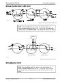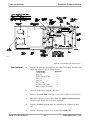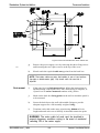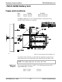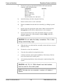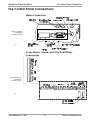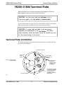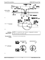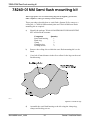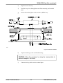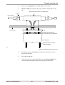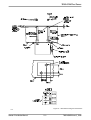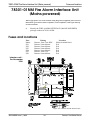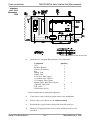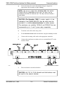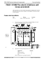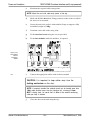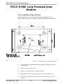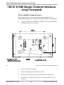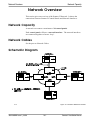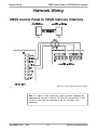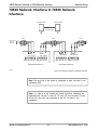
1
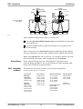
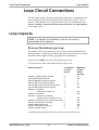
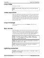
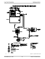
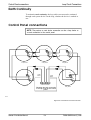
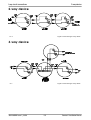
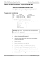
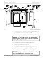
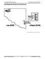
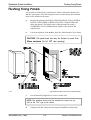
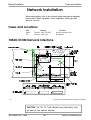
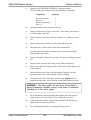
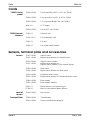
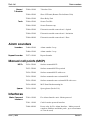
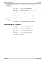
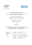
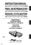
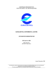
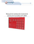
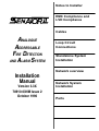
Notes to Installer
EMC Compliance and
LVD Compliance
Cables
ANALOGUE
ADDRESSABLE
FIRE DETECTION
AND ALARM SYSTEM
Loop Circuit
Connections
Standalone System
Installation
Network overview
Installation
Manual
Version 3.3X
78910-03NM Issue 2
October 1996
Network System
Installation
Parts
Preface
This is the second issue of the Installation Manual for the Senator II
system. The manual covers Senator II products that are compatible with
version 3.3X software and also includes the requirements of the Low
Voltage Directive.
The manual is a guide to be read in conjunction with the recommendations
in BS5839:Part 1:1988, which is the code of practice for Fire detection and
alarm system for buildings.
Associated Documents
78930-03NM
Operating Manual for Senator II
Conventions
NOTE: A note highlights important text that is normally hidden in the
main text.
CAUTION: A caution is given to prevent damage to equipment.
WARNING: A warning is given to of dangerous conditions that
may result in injury or death.
Issue Record
Section
Issue
Date
Prelims
1 - 21
Parts
2
2
2
10/96
10/96
10/96
Comments
This second issue covers installation of
Senator II systems and network system
products that are compatible with version 3.3X
software. The second issue also covers
changes arising from LVD requirements.
The information contained herein is the property of CARADON GENT LIMITED and is supplied without liability for errors or omissions. No part of
the manual may be reproduced in any form whatsoever without prior consent of the company. Due to the on going development of the Senator II
system the information contained in the manual is subject to change without notice.
This page left intentionally blank
Senator II Supplier Details
For any queries please contact your supplier, whose details are shown
below:
Supplier name:_______________________________________________
Address:______________________________________________________
_____________________________________________________________
_____________________________________________________________
Telephone number:____________________________________________
Fax number:_________________________________________________
This page left intentionally blank
Contents
List of Contents
Notes to Installer . . . . . . . . . . . . . . . . . . . . . 1-1
EMC Compliance . . . . . . . . . . . . . . . . . . . . . 2-1
LVD Compliance . . . . . . . . . . . . . . . . . . . . . 3-1
Cable Types . . . . . . . . . . . . . . . . . . . . . . . . 4-1
Loop cables . . . . . . . . . . . . . . . . . . . . . . . . . . . . . . 4-1
Loop Cable type and Specification . . . . . . . . . . . . . . . . 4-1
Alternative Loop cable . . . . . . . . . . . . . . . . . . . . . . 4-2
Network Cables . . . . . . . . . . . . . . . . . . . . . . . . . . . . 4-2
Loop Circuit Connections . . . . . . . . . . . . . . . . 5-1
Loop Capacity
. . . . . . . . . . . . . . . . . . . . . . . . . . . . 5-1
Devices (Outstations) per loop . . . . . . . . . . . . . . . . . . 5-1
Loop cable . . . . . . . . . . . . . . . . . . . . . . . . . . . . . . . 5-2
Cable separation . . . . . . . . . . . . . . . . . . . . . . . . . . . 5-2
Loop Coverage . . . . . . . . . . . . . . . . . . . . . . . . . . . . 5-2
Spur circuits . . . . . . . . . . . . . . . . . . . . . . . . . . . . . . 5-2
Lightning protection . . . . . . . . . . . . . . . . . . . . . . . . . 5-2
Control Panel connections . . . . . . . . . . . . . . . . . . . . . . 5-4
2-way device . . . . . . . . . . . . . . . . . . . . . . . . . . . . . . 5-5
3-way device . . . . . . . . . . . . . . . . . . . . . . . . . . . . . . 5-5
Slave (Indicator) LED Unit . . . . . . . . . . . . . . . . . . . . . 5-6
SlaveRelay Unit . . . . . . . . . . . . . . . . . . . . . . . . . . . . 5-6
Standalone System Installation . . . . . . . . . . . . . 6-1
78500-02NM Fire Alarm Control Panel Set
78910-03NM Issue 2_10/96
. . . . . . . . . . . . 6-1
Senator II Installation Manual
Contents
78500-82NM Fire Alarm Control Panel . . . . . . . . . . . . . 6-1
Fuses and locations . . . . . . . . . . . . . . . . . . . . . . . . . . 6-1
.78510-02NM Battery Unit . . . . . . . . . . . . . . . . . . . . . . 6-5
Fuses and locations . . . . . . . . . . . . . . . . . . . . . . . . . . 6-5
Fire Control Panel Connections . . . . . . . . . . . . . . . . . . . 6-7
Mains Connection . . . . . . . . . . . . . . . . . . . . . . . . . 6-7
Loop, Master Alarms and Fire/Fault Relay
Connections . . . . . . . . . . . . . . . . . . . . . . . . . . . . 6-7
78600-01NM Fire Alarm Repeat Panel Set . . . . . . . . . . . . . 6-8
78600-82NM Fire Alarm Repeat Panel . . . . . . . . . . . . . . 6-8
Fuses and locations . . . . . . . . . . . . . . . . . . . . . . . . . . 6-8
Fire Repeat Panel Connections . . . . . . . . . . . . . . . . . . . 6-10
Flushing Fixing Panels . . . . . . . . . . . . . . . . . . . . . . . . 6-11
78200-01NM Terminal Plate . . . . . . . . . . . . . . . 7-1
Terminal Plate installation
. . . . . . . . . . . . . . . . . . . . . 7-1
Fire sensors . . . . . . . . . . . . . . . . . . . . . . . . 8-1
Fitting a sensor head to terminal plate . . . . . . . . . . . . . . . 8-2
Removal of sensor head from terminal plate . . . . . . . . . . . . 8-3
To assemble a sensor head . . . . . . . . . . . . . . . . . . . . . . 8-5
78260-01NM Semi flush mounting kit . . . . . . . . . . 9-1
T-breaker and slave units . . . . . . . . . . . . . . . . 10-1
78260-01NM Duct Sensor . . . . . . . . . . . . . . . . 11-1
Manual Call Points . . . . . . . . . . . . . . . . . . . . 12-1
Surface Fixing . . . . . . . . . . . . . . . . . . . . . . . . . . . . . 12-1
Semi-Flush Fixing . . . . . . . . . . . . . . . . . . . . . . . . . . . 12-3
Senator II Installation Manual
78910-03NM Issue 2_10/96
Contents
Testing . . . . . . . . . . . . . . . . . . . . . . . . . . . . . . . . . 12-3
Alarm Sounders
. . . . . . . . . . . . . . . . . . . . . 13-1
78277-01NM Repeat Sounder . . . . . . . . . . . . . . . . . . . . 13-2
78301-01NM Fire Alarm Interface Unit
(Mains powered) . . . . . . . . . . . . . . . . . . . . . 14-1
Fuses and locations . . . . . . . . . . . . . . . . . . . . . . . . . . 14-1
78321-01NM Fire alarm interface unit
(Loop powered) . . . . . . . . . . . . . . . . . . . . . . 15-1
Fuses and Locations . . . . . . . . . . . . . . . . . . . . . . . . . 15-1
78345-06NM Power Supply Unit . . . . . . . . . . . . 16-1
Fuses and Locations . . . . . . . . . . . . . . . . . . . . . . . . . 16-1
78310-01NM Loop Powered Zone Module . . . . . . . 17-1
78315-01NM Single Channel Interface
(Loop Powered) . . . . . . . . . . . . . . . . . . . . . . 18-1
Network Overview . . . . . . . . . . . . . . . . . . . . 19-1
Network Capacity . . . . . . . . . . . . . . . . . . . . . . . . . . . 19-1
Network Cables . . . . . . . . . . . . . . . . . . . . . . . . . . . . 19-1
Schematic Diagram . . . . . . . . . . . . . . . . . . . . . . . . . . 19-1
Network Installation . . . . . . . . . . . . . . . . . . . 20-1
Fuses and Locations . . . . . . . . . . . . . . . . . . . . . . . . . 20-1
78520-01NM Network Interface . . . . . . . . . . . . . . . . . . . 20-1
Network Wiring . . . . . . . . . . . . . . . . . . . . . . 21-1
78500 Control Panel to 78520 Network Interface . . . . . . . . . 21-1
78910-03NM Issue 2_10/96
Senator II Installation Manual
Contents
78520 Network Interface to 78520 Network Interface . . . . . . . 21-2
Senator II . . . . . . . . . . . . . . . . . . . . . . . . . 22-3
Introduction . . . . . . . . . . . . . . . . . . . . . . . . . . . . . . 22-3
Control and indicating equipment . . . . . . . . . . . . . . . . . . 22-3
Cards . . . . . . . . . . . . . . . . . . . . . . . . . . . . . . . . . 22-4
Sensors, terminal plate and Accessories . . . . . . . . . . . . . . . 22-4
Alarm sounders . . . . . . . . . . . . . . . . . . . . . . . . . . . . 22-5
Manual call points (MCP) . . . . . . . . . . . . . . . . . . . . . . 22-5
Interfaces . . . . . . . . . . . . . . . . . . . . . . . . . . . . . . . 22-5
Manuals & Accessories . . . . . . . . . . . . . . . . . . . . . . . . 22-6
Senator II Installation Manual
78910-03NM Issue 2_10/96
Contents
List of Figures
Figure 2-1 Cable termination . . . . . . . . . . . . . . 2-3
Figure 5-1 Typical fire alarm system . . . . . . . . . . 5-3
Figure 5-2 Connections to the Control Panel . . . . . . 5-4
Figure 5-3 Connecting a 2-way device . . . . . . . . . . 5-5
Figure 5-4 Connecting a 3-way device . . . . . . . . . . 5-5
Figure 5-5 Connecting a slave Indicator unit . . . . . . 5-6
Figure 5-6 Connecting slave relay unit . . . . . . . . . 5-6
Figure 6-1 Control Panel with the door open . . . . . . 6-2
Figure 6-2 Control Panel Back box shown without door 6-3
Figure 6-3 Connection of Battery cable assembly . . . 6-4
Figure 6-4 Close fitting the Panel and Battery Unit . . 6-5
Figure 6-5 Control Panel Mains connection details . . 6-7
Figure 6-6 Control Panel cable connection points . . . 6-7
Figure 6-7 Repeat Panel back box . . . . . . . . . . . . 6-9
Figure 6-8 Repeat panel connection points . . . . . . . 6-10
Figure 6-9 Flush fixing the Control or Repeat Panel . . 6-11
Figure 7-1 78200-01NM Terminal Plate . . . . . . . . 7-1
Figure 7-2 Fixing the terminal plate to a ceiling tile . . 7-2
Figure 7-3 Terminal Plate connections . . . . . . . . . 7-2
Figure 7-4 Wiring the terminal plate . . . . . . . . . . 7-2
78910-03NM Issue 2_10/96
Senator II Installation Manual
Contents
Figure 8-1 Fitting a sensor head to terminal plate . . . 8-2
Figure 8-2 Removal of the chamber module . . . . . . 8-3
Figure 8-3 Removal of electronics from terminal plate
8-4
Figure 8-4 Fitting together chamber and electronics . 8-5
Figure 9-1 Cutouts for lugs
. . . . . . . . . . . . . . . 9-1
Figure 9-2 Flush kit installation . . . . . . . . . . . . . 9-2
Figure 10-1 T-breaker and slave units . . . . . . . . . 10-1
Figure 10-2 Fitting a t-breaker or slave unit . . . . . . 10-2
Figure 11-1 Duct Sensor fixing and connections . . . . 11-2
Figure 12-1 Manual Call Point parts . . . . . . . . . . 12-2
Figure 13-1 Alarm Sounder fixing and connections . . 13-1
Figure 14-1 Interface Unit with the door open . . . . . 14-1
Figure 14-2 Interface unit with the door open . . . . . 14-2
Figure 14-3 Connections Details . . . . . . . . . . . . . 14-3
Figure 15-1 Interface unit fixing and connections . . . 15-1
Figure 15-2 Line module internal connection details . 15-2
Figure 16-1 Supply Unit fixing details
. . . . . . . . . 16-1
Figure 16-2 PSU to interface unit connections . . . . . 16-2
Figure 17-1 Loop powered zone module
with lid removed . . . . . . . . . . . . . . . . . . . . . 17-1
Figure 18-1 Single Channel Interface (lid removed) . . 18-1
Senator II Installation Manual
78910-03NM Issue 2_10/96
Contents
Figure 19-1 Senator II Network Schematic . . . . . . . 19-1
Figure 20-1 Network Interface Fixing and Connections 20-1
Figure 21-1 Control Panel to . . . . . . . . . . . . . . . 21-1
Figure 21-2 Network Interface to . . . . . . . . . . . . 21-2
78910-03NM Issue 2_10/96
Senator II Installation Manual
Contents
This page left intentionally blank
Senator II Installation Manual
78910-03NM Issue 2_10/96
Notes to Installer
Installation requirements
Notes to Installer
The manual contains fixing and wiring information to cover the installation
of the Senator II system, both Standalone and Network.
Installation
requirements
It is recommended that the installer follows the general requirements of
BS5839:Part 1:1988, which is the code of practice relating to the fire
detection and alarm systems for buildings. The relevant parts of the Institute
of Electrical Engineers Wiring Regulations 16th edition must also be
followed.
Second fix
installation
To prevent the possibility of damage or dirt degrading the performance or
appearance of the Senator II products, the installation of second fix items
should be delayed until all major building work in the area is complete (e.g.
clearing and sweeping).
Fixture and
fittings
It is the installers responsibility to provide adequate fixtures and fittings for
the type of construction surface onto which a product is to be installed,
whilst utilising the fixing points on the respective product. As an aid to this
decision, the weight and overall size of each full assembly together with
implications on cable entries and routing should be taken into consideration.
NOTE: All these procedures assume that the cable, glands, steel boxes
(BESA boxes) and other related accessories are provided by the installer.
Location
The installer should acquire site specific information from the interested
parties, for details on the location of products for installation. The acquired
information together with this guide and the relevant standards should be
used to assist the work.
Each product assembly can be identified from its package label. The
contents of all packages should be checked for any discrepancies.
Fire sensor
covers
Each fire sensor may be supplied with a plastic dust cover. If supplied then
the dust cover must be fitted to prevent dust and dirt from the building
work from contaminating the sensor.
78910-03NM Issue 2_10/96
1-1
Senator II Installation Manual
Parts for later installation
Parts for later
installation
Notes to Installer
All unused parts should be retained in their respective container for safe
keeping until required.
NOTE: The installation of all outstanding parts is usually carried out
during Commissioning of the System.
Loop earth
continuity
To maintain earth continuity on a loop, the loop cable screen must be
connected through each system device on the loop, whether the earth is
connected to a device or not
NOTE: The network cable screen is earthed at one end only.
Mains supply
Mains supply to fire alarm control and indicating equipment must be via an
unswitched fused spur unit.
The fused spur isolator cover should be red and marked:
FIRE ALARM - DO NOT SWITCH OFF
Each of the fire alarm equipments’ fused spur units must be fed from a
dedicated switch or protective device at the local mains supply distribution
board.
Mains and
battery supply
connections
The mains and battery supply cables must be installed to the stage to
facilitate the power up for commissioning.
WARNING: Where mains cable are to remain disconnected,
their tail ends must be insulated to prevent dangerous
conditions arising in the event of accidental switching On of
the mains supply
Cable
termination
and connection
Terminate each cable at the entry point to the enclosure, using the cable
manufacturer’s recommended techniques.
Where the cable is required to be connected, ensure it is secure to the
respective terminal.
Where the cable is not required to be connected, leave 400mm (unless
otherwise specified) tail wire length and mark each core identifying its
final point of connection.
Wiring test
CAUTION: DO NOT undertake high voltage insulation tests
WITH THE CABLES CONNECTED to their terminals. Such a
test may damage the electronics circuitry in loop devices and
panels.
Senator II Installation Manual
1-2
78910-03NM Issue 2_10/96
EMC Compliance
Introduction
EMC Compliance
Installation guidelines for compliance with the
requirements of the Electromagnetic
Compatibility (EMC) Directive
Introduction
These guidelines should be followed to meet the requirements of the EMC
directive in force within the European Union, to prevent the reception
and emission of electromagnetic interference into and out of the analogue
addressable fire detection and alarm system.
Products
The products covered by these guidelines are listed under EMC compliant
products, see list on the last page of this section.
Code of
practice
The installer must follow BS7671 : 1992 Requirements for Electrical
installations, IEE wiring regulations 16th edition if installation is in the United
Kingdom, UK.
Cables
The following cables have been tested against EMC directives for use with
with fire detection and alarm applications:
(see also the Cable types part of Installation manual for further information)
For loop circuit, battery connection and master alarm circuit wiring:
• Mineral Insulated Copper Cable (MICC)
• FIRETUF OHLS Cable type: FTZ2E1.5
For network interface to network interface or control panel to
network interface wiring:
• Mineral Insulated Copper Cable1 (MICC)
• Belden Cable No 9729 (UL Style 2493)
• Armoured Cable2
By armouring the Belden Cable No 9729 (UL Style 2493)
In the UK, the guidance of BS5839 : Part 1 should also be followed.
1
The Mineral Insulated Copper Cable should be used for fire resistant applications.
2
The cable manufacturer cannot guarantee the cable specification if it is armoured.
78910-03NM Issue 2_10/96
2-1
Senator II Installation Manual
Cable Separations
Cable
Separations
EMC Compliance
The cables of the fire detection and alarm system and other systems should
usually be separated by at least 160mm, unless dedicated conduit or ducting
is being used.
In the UK there is additional guidance provided in a document reference
‘Recommended cable separations to achieve electromagnetic compatibility
in buildings’ obtainable from the Electrical Contractors Association.
Earth continuity
All earth connection points should be clean to provide a good electrical
conductivity path.
To maintain the earth continuity:
all earth leads and fittings provided should be installed
the loop cable screen must be continued through each system device on
the loop, whether the earth is connected to the device or not.
see also Cable termination.
NOTE: Do not use any part of building structure for earthing.
A zinc coating is provided around the termination point, on the inside of an
equipment metal enclosure. This provides a good electrical conductivity
path for cable earth termination.
CAUTION: The zinc coating should not be damaged. Any
damage will expose bare metal, which can corrode and make
poor earth connection.
There are copper fingers fitted to the control and indicating equipment to
fill the gap between enclosure and cover. The fingers provide a shield
against electromagnetic and radio frequency interferences.
CAUTION: It is important to avoid damage to the copper
fingers, as this can re-introduce gap between enclosure and
cover.
Mains Supply
Cable
termination
The mains supply to mains operated equipment should enter the enclosure
by a dedicated entry, which is the closest to the mains connection points.
Use only cable manufacturers recommendations for cable termination.
The wires between the termination point and terminals should be short and
as straight as possible.
Senator II Installation Manual
2-2
78910-03NM Issue 2_10/96
EMC Compliance
Board fixing
MICC
CABLE TERMINATION
FireTuf
CABLE TERMINATION
MICC CABLE
FireTuf CABLE
GLAND
EARTH
DRAIN
WIRE
Should not
be more than
50mm
ZINC PLATED
LOCK WASHER
Figure 2-1 Cable
termination
GLAND
PANEL
enclosure
BRASS
LOCKNUT
BOARD
TERMINALS
fl198
Where Mineral insulated cable (MICC) is being used:
use only galvanised finish junction boxes for installation of alarm and
detection devices
use brass locknut with zinc plated lockwasher to secure gland to the
metal enclosure.
There is no need to use earth tail seals when terminating mineral insulated
cable, providing there is good earth continuity between gland and enclosure.
When using Firetuf cable, the earth drain wire should be fitted to the earth
point nearest the cable entry, with a length not exceeding 50mm.
Board fixing
EMC compliant
products
Ensure all board fixing screws are fully tightened, if they have been
removed during installation. The screws maintain an earth continuity path
between the board and its metal enclosure.
The products listed below are those covered by these guidelines.
Note, the product options are not listed.
Control and
indicating
equipment:
78500-02NM
78600-01NM
Interface
equipment:
78301-01NM
78321-01NM
78345-06NM
78310-01NM
78315-01NM
78910-03NM Issue 2_10/96
Fire Sensors:
78200-01NM
78215-01NM
78275-01NM
78220-01NM
78230-01NM
78260-01NM
78285-01NM
2-3
Manual Call Point:
78150-52NM
78155-52NM
78150-22NM
78150-55NM
78150-25NM
Tee Breaker and
Slave Units:
78299-01NM
78299-02NM
78299-03NM
Alarm Sounder:
78400-02NM
78400-03NM
78277-01NM
Network:
78520-01NM
Senator II Installation Manual
EMC compliant products
EMC Compliance
This page has been intentionally left blank.
Senator II Installation Manual
2-4
78910-03NM Issue 2_10/96
LVD Compliance
Introduction
LVD Compliance
Installation guidelines for compliance with the
requirements of the Low Voltage Directive (LVD)
Introduction
Products
These guidelines should be followed to meet the requirements for the safety
of Information Technology equipment, including electrical business
equipment - BS EN 60950: 1992.
All Senator II Panels.
Guidelines
Ensure the EMC Compliance Guidelines are followed.
Each of the Fire Alarm equipments’ fused spur units must be fed from a
dedicated switch or protective device at the local mains supply distribution board. If a single pole disconnect device is used (on Live Side)
then the Neutral (N) should be clearly labelled.
Cable Glands should be used on the equipment for the mains supply cable.
Unused knockouts that have been removed, should not be left open.
Power supply cords shall:
• If rubber insulated, be of synthetic rubber and not lighter than
ordinary tough rubber sheathed flexible cord according to IEC 245
(designation H05 RR-F).
• If polyvinyl chloride (PVC) insulated and for equipment having a
mass exceeding 3kg, be not lighter than ordinary polyvinyl
chloride sheathed flexible cord (designation H05 VV-F or H05
VVH2-F2).
• Include, in the case of Class 1 Equipment, a green/yellow
protective earthing conductor electrically connected to the
protective earthing terminal within the equipment and connected
to the protective earthing contact of the plug, if any.
• Have conductors with cross sectional areas of not less than
0.75mm.
NOTE: For rated currents of up to 3A, a nominal cross sectional area of
0.5mm2 is permitted provided the length of the cord does not exceed 2m.
78910-03NM Issue 2_10/96
3-1
Senator II
Guidelines
LVD Compliance
This page left blank intentionally.
Senator II
3-2
78910-03NM Issue 2_10/96
Cable Types
Loop cables
Cable Types
Loop cables
The cable is an important part of the Senator II fire alarm system, which
carries both communication data and power supplies. Its integrity is
therefore essential for fire detection and alarm signals to be processed to
keep the system operational.
Loop Cable type and Specification
Mineral insulated copper cable (EMC Compliant)
• BS6207: Part 1
• fire resistance tested to BS6387 categories CWZ
• having continuous metal sheath encapsulating
• 2- cores
• each core having 1.5mm2 cross section area
• a red cover sheath (preferred for alarm applications)
• core to core capacitance 190pF/m
• core to screen capacitance 220pF/m
Delta Crompton FDZ2E1.5 FireTuf OHLS fire resistant data cable
(EMC Compliant)
• Two core plus earth wire
• each core having 1.5mm2 cross sectional area
• to BS6387 categories CWZ
• core to core capacitance 115pF
• core to screen capacitance 205pF/m
Loop cable
usage
Must not exceed 1Km, this includes the cable usage on main loop and spur
circuits.
NOTE: Multicore cables having more than 2-cores are not allowed for
loop wiring, due to inadequate separation and possible electrical
interference problems.
78910-03NMIssue 2_10/96
4-1
Senator II Installation Manual
Network Cables
Cable Types
Alternative Loop cable
CAUTION: In countries where the European EMC directive is
in force, only those cables detailed in the EMC Compliance
part of this manual may be used.
Alternative cable types with may be acceptable providing:
The cable is to BS6387 having
• typically no more than 1km cable usage per loop circuit
• no more than 2 - cores
• a maximum of 0.5uF total intercore capacitance
• a maximum of 13 ohms per core
• each core having no less than 1.5mm2 cross section area
• with an inherent or through metal conduit screen for earth
continuity in order to produce electrical protection and screening
• having protection from heat and mechanical damage
• the cable screen must be capable of being earthed at each system
device (outstation)
Network Cables
CAUTION: In countries where the European EMC directive is
in force, only those cables detailed in the EMC Compliance
part of this manual may be used.
The cable used to connect: 78500 Control Panels to 78520 Network
Interfaces and 78520 Network Interfaces to each other MUST be one of
the following
Recommended
Cables
Huber & Schner Radox series FR communication cable
1200m maximum Network Interface to Network Interface
10m maximum Control Panel to Network Interface
• Three core twisted triad screened
• 1.5mm2 (7/0.42 stranded) conductors
• Nominal impedance 200ohms (1KHz)
• Capacitance between conductors 110pF/m (1KHz)
• Capacitance between screen to core 210pF/m (1KHz)
• Fire resistance tested to BS6387 category CWZ and IEC 331.
Senator II Installation Manual
4-2
78910-03NMIssue 2_10/96
Cable Types
Network Cables
Mineral insulated copper cable (EMC Compliant)
600m maximum Network Interface to Network Interface
10m maximum Control Panel to Network Interface
• BS6207: Part 1
• 3 parallel cores
• having continuous metal sheath encapsulating
• each core having 1.5mm2 cross section area
• a red cover sheath (preferred for alarm applications)
Belden No 9729 (UL Style 2493)
Teflon jacketed Belden TR No. 89729
1200m maximum Network Interface to Network Interface
10m maximum Control Panel to Network Interface
Both cables must have following characteristics:
• Two twisted pairs
• Each pair individually screened
• 24AWG (7 strands x 32 AWG)
• Low capacitance between conductors - 41pF/m at 1kHz
• Low capacitance conductor to screen - 76pF/m at 1kHz
• Temperature range -30oC to +60oC . o
(Teflon jacketed cable 89729 up to 200 C)
Belden Armoured equivalent (EMC Compliant)
800m maximum Network Interface to Network Interface
10m maximum Control Panel to Network Interface
being a two pair cable to BS5308:Part 1 (type 2)
• This cable
0.5mm2 (16/0.2mm).
Belden No. 9842 EIA RS485 Applications, O/A Beldfoil® Braid
1200m maximum Network Interface to Network Interface
10m maximum Control Panel to Network Interface
Must have following characteristics:
• Two twisted pairs
• 24AWG (7 strands x 32 AWG) conductors
• Low characteristic impedance - 120 ohms
• Low capacitance between conductors - 42pF/m at 1kHz
• Low capacitance conductor to screen - 75.5pF/m at 1kHz
Beldfoil is a registered trademark.
78910-03NMIssue 2_10/96
4-3
Senator II Installation Manual
Network Cables
Cable Types
This page has been intentionally left blank
Senator II Installation Manual
4-4
78910-03NMIssue 2_10/96
Loop Circuit Connections
Loop Capacity
Loop Circuit Connections
The fire alarm system can permit significant reductions in installation costs
when compared with conventional and other multi-state systems. This is
because of the ability to wire a large number of devices (outstations), like
sensors, sounders, manual call points, interface units and repeat panels
on one loop circuit.
Loop Capacity
NOTE: It is important that redundancy is built into the system to
accommodate future expansions.
Devices (Outstations) per loop
The number of devices (outstations) on one loop circuit can be limited by
the total number of addresses available, the electrical load on the circuit, the
maximum cable length and other geographical considerations.
A maximum of 200 devices are allowed per loop circuit:
As a general rule allow 1000 load factor per loop circuit.
Code and device
Load factor
for each
device
Maximum
of each
device
per loop
78400-02, 78400-03 Alarm sounder
78277-01NM Repeat Sounder
78301-01NM Mains powered interface
78321-01NM Loop powered interface
78310-01NM Loop powerered Zone Module
78315-01NM Single Channel Interface
78299-02 or 78299-03
Slave LED or Relay unit
78299-01 Tee breaker
78215-01 or 78220-01 or 78230-01
Optical, Heat or Ionisation sensor
78260-01 Duct Sensor (also needs a Slave LED)
78275-01 Optical Sensor Sounder
78285-01NM Heat Sounder
78150 or 78155 Manual call point
78600-01 Repeat Panels
25
8
3
2
25
10
40
125
8
30
40
100
1
1
50‡
200
1
1
8
8
1
3
200
50‡
125
125
200
32
‡ Installations prior to March 1996 have a maximum of 10 slave devices.
78910-03NM Issue 2_10/96
5-1
Senator II Installation Manual
Loop cable
Loop Circuit Connections
Loop cable
See the part on Cables
NOTE: Multi-core cables carrying more than one circuit should never be
used.
Cable separation
Where the outgoing and return cables of a loop which covers more than the
equivalent of one zone must not run together, for example, either close to
the Control Panel or in a service duct. There should be as much physical
separation as possible between the cables and the mechanical protection of
the cable should be to a particularly high standard. This is to minimise the
risk of accidental damage to both cables. There should be separation from
the mains supply cable.
Loop Coverage
A loop circuit must not cover more than 10,000m2 of floor area of a
protected site.
Spur circuits
Where appropriate, a spur circuit may be used in order to save cable and,
therefore, installation cost. A device (outstation) has terminals for cable
connections. The 2-way type allows straight in-out connection, while the
3-way has an added common line connection, that is in-out-comm line.
The spur circuit must always be taken from the line com terminals.
NOTE: 3-way devices are only available as sounders, interfaces and
repeats. If it is not appropriate to use these devices in the required
location a ‘T’ breaker should be used.
NOTE: Spurs should not cover more than the equivalent of one zone as
defined in BS 5839 : Part 1 : 1988.
NOTE: The common line to accept spurs may be left unconnected, if
using the device for 2-way connection.
Lightning protection
CAUTION: Lightning protection must be used if a loop cable is routed on
exterior wall of a building.
Senator II Installation Manual
5-2
78910-03NM Issue 2_10/96
Loop Circuit Connections
Lightning protection
Figure 5-1 Typical fire alarm system
cdn1
78910-03NM Issue 2_10/96
5-3
Senator II Installation Manual
Control Panel connections
Loop Circuit Connections
Earth Continuity
To maintain earth continuity, the loop cable screen must be continued
through each system device on the loop, whether the device is earthed or
not..
Control Panel connections
NOTE: The previous or next device connection can be a loop device or
an end connection to the control panel.
L1
L1
L1
L2
L2
L2
OV
OV
OV
2-way device
2-way device
2-way device
L1
L1
L2
LOOP
END 1
LOOP
END 2
L2
OV
OV
OV
2-way device
L1
OV L2
CONTROL PANEL
Showing two end connection
of a loop circuit at the control
panel
2-way device
fl174
Figure 5-2 Connections to the Control Panel
Senator II Installation Manual
5-4
78910-03NM Issue 2_10/96
Loop circuit connections
2-way device
2-way device
Figure 5-3 Connecting a 2-way device
shfl172
3-way device
Figure 5-4 Connecting a 3-way device
cdn16
78910-03NM Issue 2_10/96
5-5
Senator II Installation Manual
Slave (Indicator) LED Unit
Loop circuit connections
Slave (Indicator) LED Unit
shfl104
Figure 5-5 Connecting a slave Indicator unit
NOTE: The slave LED unit must always be connected before the
respective master sensor relative to End 1 of the loop. The slave LED
‘attaches’ itself to the master sensor and reflects the state of this device
Remote auxiliary
equipment
LOOP
OUT
LOOP
IN
L1
LOOP
IN
L2
Device
L2
OV
OV
L1
TOWARDS
END 1
LOOP
OUT
L1
0V
L2
0V
C
Next Device
N/C N/O
TOWARDS END 2
2-way device
2-way device
Slave Relay Unit
Master Sensor
shfl105
Figure 5-6 Connecting slave relay unit
SlaveRelay Unit
NOTE: The slave Relay unit must always be connected before the
respective master sensor relative to End 1 of the loop. The slave relay
unit ‘attaches’ itself to the master sensor and reflects the state of this
device.
Senator II Installation Manual
5-6
78910-03NM Issue 2_10/96
Standalone System Installation
78500-02NM Fire Alarm Control Panel Set
Standalone System Installation
78500-02NM Fire Alarm Control Panel Set
The 78500-02NM Control Panel Set consists of two (or more) packages:
78500-82NM Fire Alarm Control Panel
78510-02NM Battery Unit
78534-82NM Power Supply Unit and/or 1-5 Cards (see supplier for details)
78500-82NM Fire Alarm Control Panel
Where appropriate refer to as fitted wiring diagrams (if supplied), general notes,
EMC compliance, LVD Compliance, cable types and loop circuit connections.
Fuses and locations
Fuse
Rating
Mains
20mm x 5mm 3.15A SD
FS1
20mm x 5mm 1A HRC#
FS2
20mm x 5mm 1A HRC#
FS1
20mm x 5mm 8A QB
FS2
20mm x 5mm 8A QB
FS3
Not fitted
FS4
Not fitted
FS5
20mm x 5mm 8A QB
FS6
20mm x 5mm 8A QB
# - Master Alarm fuses
Location
Mains terminal block
Master alarm terminal board
Master alarm terminal board
Power supply pcb
Power supply pcb
Power supply pcb
Power supply pcb
The control panel can be surface or flush mounted. If however the battery
Unit is to be close fitted beneath the control panel then the two can only be
surface mounted.
CAUTION: 4off 12V @ 12.0Ah Sealed Lead Acid batteries
must be used for the control panel.
NOTE: The battery box can accomodate up to 8 batteries to allow for
additional standby time.
78910-03NM Issue 2_10/96
6-1
Senator II Installation Manual
Fuses and locations
Standalone System Installation
cdn2
Figure 6-1 Control Panel with the door open
Door removal
a)
Identify the package labelled FIRE ALARM CONTROL PANEL and
check the contents, which should include:
Component
Quantity
Control panel
1
Door key
1
Enable controls key
2
Fuse 1A
2
Fuse 8A
1
Fuse 3.15A
1
Resistor 22K Ohms
2
Battery cable assembly
1
b)
Open the panel door using the door key.
c)
Remove the earth lead from upper case earth to PSU terminal block.
d)
Disconnect the two ribbon cables from the display/keyboard board,
located on the inside-left of the door assembly.
e)
Remove the door from the back box assembly, by sliding it up and
off.
f)
Remove the power supply cover to back box earth lead.
Senator II Installation Manual
6-2
78910-03NM Issue 2_10/96
Standalone System Installation
Fuses and locations
Figure 6-2 Control Panel Back box shown without door
g)
Remove the power supply cover by removing the three fixing screws
and loosening the two captive screws at the top of the cover.
h)
Knock out/in the required cable entry points from the back box.
cdn3
NOTE: The battery cable can enter the backbox in one of two locations
(top-right or bottom-center right). Only knock out/in the one that is
required.
Flush mount
i)
If the panel is to be flush mounted then follow the instructions for
flush mounting control panel now. Once flush fixing is complete, or
if panel is to be surface mounted continue with j) below.
j)
Mark out the back box fixing points on the wall to which the panel is
to be mounted.
k)
Secure the back box to the wall with suitable fixings to provide
adequate support for a full assembly weight of 16kg.
l)
Terminate each cable at the entry point leaving 400mm tail wire
length and mark each core to identify its intended connection point.
WARNING: The mains cable tail ends must be insulated to
prevent dangerous conditions arising in the event of accidental
switching ON of the mains supply.
78910-03NM Issue 2_10/96
6-3
Senator II Installation Manual
Fuses and locations
Battery unit
Standalone System Installation
m)
Power supply
assembly
If the battery Unit is to be close fitted beneath the control panel then
follow the battery Unit fixing instructions now. Once the battery unit
is installed, or if it is to be installed remotely continue with n) below.
NOTE: It is recommended that the power supply assembly is left until
the commissioning process to avoid damage to the power supply
occuring during any subsequent building process
n)
Fit and secure the power supply assembly to the back box by
tightening the five captive-screws.
o)
Connect the two ribbon cables (from the back plane and terminal
card) and the battery cable assembly to the power supply board.
NOTE: For top cable entry the battery cables to be routed to the top
battery connection board. For bottom cable entry the battery cables to be
routed to the backplane board located in the bottom of the panel.
Figure 6-3 Connection
of Battery cable
assembly
Door refitting
p)
Connect the earth lead and mains live and neutral from mains filter
to PSU terminal block.
q)
Secure the power supply cover using previously removed three
screws plus the two captive screws.
r)
Slide on the door to the back box assembly, ensure the door can open
and close easily.
s)
Connect the previously removed ribbon cables to the controller board
on the door assembly.
t)
Fit the door to back box earth lead.
u)
Ensure all cables are secured to the base of the back box.
v)
Close the door and lock it using the door key. All remaining
installation is done during the commissioning of the system
Senator II Installation Manual
6-4
78910-03NM Issue 2_10/96
Standalone System Installation
.78510-02NM Battery Unit
.78510-02NM Battery Unit
Fuses and locations
Fuse
Batt1
Batt2
Rating
20mm x 5mm 8A
20mm x 5mm 8A
Location
Battery fuse board
Battery fuse board
The battery Unit may be close fitted beneath the control panel using
standard conduit fittings (not supplied).
cdn4
Figure 6-4 Close fitting the Panel and Battery Unit
To maintain earth continuity an earth lead (not supplied) is required to be
connected between to an earth point in the control panel and battery Unit.
NOTE: The coupling length must not be less than 72mm.
Cable and
Distance
The recommended cable type is MICC. The following maximum cable
lengths must not be exceeded:
MICC 1.5mm2
MICC 2.5mm2
78910-03NM Issue 2_10/96
6-5
10m max.
15m max.
Senator II Installation Manual
Fuses and locations
Standalone System Installation
a)
Identify the package labelled BATTERY UNIT and check the
contents, which should include:
Component
Quantity
Battery Unit
1
Door key
1
Fuse 8A (Battery)
2
Battery cable loom
2
Battery link
4
Nut and washer (for earth stud)
1
b)
Open the battery unit door using the door key.
c)
Remove the back box to door earth lead.
d)
Remove the door from the back box assembly, by sliding it up and
off.
e)
Knock out/in the appropriate cable entries. Mark out the back box
fixing points on the wall to which the box is to be mounted.
f)
Secure the back box to the wall with suitable fixings to provide
adequate support for a full assembly weight of 40kg, (with all 8
batteries installed).
CAUTION: Do not make the battery connections. This is done
during commissioning stage.
g)
Slide the door on to the back box assembly, ensure the door can open
and close easily.
h)
Fit the door to back box earth lead.
i)
Close the door and lock it using the door key.
j)
Continue with the control panel installation, if the battery Unit has
been close fitted to the control panel.
k)
All remaining installation is done during the commissioning of the
system.
CAUTION: 4off 12V @ 12.0Ah Sealed Lead Acid batteries
must be used for the control panel.
NOTE: The battery box can accomodate a maximum of 8 batteries if
required.
Senator II Installation Manual
6-6
78910-03NM Issue 2_10/96
Standalone System Installation
Fire Control Panel Connections
Fire Control Panel Connections
Mains Connection
Figure 6-5 Control
Panel Mains
connection details
cdn5
Loop, Master Alarms and Fire/Fault Relay
Connections
Figure 6-6 Control
Panel cable
connection points
cdn7
78910-03NM Issue 2_10/96
6-7
Senator II Installation Manual
78600-01NM Fire Alarm Repeat Panel Set
Standalone System Installation
78600-01NM Fire Alarm Repeat Panel Set
78600-82NM Fire Alarm Repeat Panel
Where appropriate refer to as fitted wiring diagrams (if supplied), general notes,
EMC compliance, LVD Compliance, cable types and loop circuit connections.
Fuses and locations
Fuse
Mains
FS1
FS2
Rating
20mm x 5mm 1A SD
20mm x 5mm 2.5A QB
20mm x 5mm 2.5A QB
Location
Mains terminal block
MRC pcb
MRC pcb
The repeat panel can be surface or flush mounted.
a)
Identify the FIRE ALARM REPEAT PANEL package and check the
contents, which should include:
Component
Quantity
Repeat panel
1
Fuse 1A
1
Fuse 2.5A
1
Door key
1
Enable controls key
1
CAUTION: 2off 12V @ 7.0Ah Sealed Lead Acid batteries must
be used for the repeat panel.
b)
Open the panel door using the door key.
c)
Remove the backbox to door earth lead.
d)
Disconnect the two ribbon cables from the main controller board,
mounted on inside of door.
e)
Remove the door.
f)
Remove the back box to cover earth lead.
g)
Loosen the cover captive screw and then remove the cover.
h)
Knockout the required cable entry points from the back box.
i)
If the panel is to be flush mounted then follow the instructions for
flush mounting the repeat panel now.
j)
Mark out the 3 back box fixing points on the wall to which the panel
is to be mounted.
Senator II Installation Manual
6-8
78910-03NM Issue 2_10/96
Standalone System Installation
Fuses and locations
Figure 6-7 Repeat Panel back box
cdn11
k)
Secure the back box to the wall with suitable fixings to support a full
assembly weight, including the batteries, of 14kg.
l)
Terminate the cable at the entry point leaving 400mm tail wire length.
WARNING: The mains cable tail ends must be insulated to
prevent dangerous conditions arising in the event of accidental
switching ON of the mains supply.
m)
Secure the cover to the back box using the captive screw.
n)
Replace the cover to back box earth lead.
o)
Re-fit the door, earth lead and ribbon cables previously removed.
p)
Close the door and lock it using the door key. All remaining
installation is done during the commissioning of the system.
CAUTION: Do not connect the mains and battery cables, these
will be connected during the commissioning stage.
78910-03NM Issue 2_10/96
6-9
Senator II Installation Manual
Fire Repeat Panel Connections
Standalone System Installation
Fire Repeat Panel Connections
Figure 6-8 Repeat panel connection points
Senator II Installation Manual
6-10
78910-03NM Issue 2_10/96
Standalone System Installation
Flushing Fixing Panels
Flushing Fixing Panels
It is possible to flush fix the control panel, with or without the battery box,
and the repeat panel. The following does not cover the battery unit in detail,
however the method is the same.
a)
Identify the package labelled FLUSH MOUNTING FOR CONTROL
PANEL (78500-29NM) or REPEAT PANEL (78600-29NM) and
check the shroud. The battery unit is flush mounted by using a
COMBINED (78510-29NM) shroud, which is also used for the
control panel.
b)
Cut out an aperture in the wall to allow the flush shroud is to be fitted.
CAUTION: The panel back box may be flushed no more than
92mm maximum (for full 180o door opening).
emfl63
Figure 6-9 Flush fixing the Control or Repeat Panel
c)
Use the shroud fixing holes to secure it to the wall.
NOTE: The combined shroud must be mounted the correct way up look for the ‘TOP’ sign on the shroud.
d)
78910-03NM Issue 2_10/96
Continue with the control or repeat panel installation instructions.
6-11
Senator II Installation Manual
Flushing Fixing Panels
Standalone System Installation
This page left intentionally blank.
Senator II Installation Manual
6-12
78910-03NM Issue 2_10/96
78200-01NM Terminal Plate
Terminal Plate installation
78200-01NM Terminal Plate
Where appropriate refer to as fitted wiring diagrams (if supplied), general notes,
EMC compliance, cable types and loop circuit connections.
CAUTION: Use the correct tool and technique to fit or
remove any part of the fire sensor or terminal plate.
To provide the right coverage, each fire sensor must be fitted to a terminal
plate in the location as defined by the site specific information.
CAUTION: To prevent dirt and dust in the environment
degrading the performance of the fire sensors, the sensor
head installation should be carried out by the installer just prior
to the commissioning of the system.
Terminal Plate installation
The following illustrations provide information on how to install and wire
the sensor terminal plate.
ELONGATED FIXING
HOLE FOR
CABLE
ENTRY
LOOP CABLE
CONNECTION
POINTS
L1
Figure 7-1 78200-01NM
Terminal Plate
L2
OV
LED POSITION
WHEN THE
SENSOR HEAD
IS FITTED TO
THE BASE
METALISED COATING
TO FACILITATE BASE
EARTH CONTINUITY
TO LOOP CABLE
SCREEN, VIA STEEL
BOX FIXING
KEYHOLE FIXING
fl112
78910-03NM Issue 2_10/96
7-1
Senator II Installation Manual
Terminal Plate installation
78200-01NM Terminal Plate
Figure 7-2 Fixing
the terminal plate
to a ceiling tile
fl114
Figure 7-3 Terminal Plate
connections
shfl113
Earthing
requirements
Terminal Plate
wiring
NOTE: It is essential that earth continuity is independently maintained
around the loop via the cable screen.
To correctly wire the terminal plate:
Figure 7-4 Wiring the
terminal plate
fl374
Senator II Installation Manual
7-2
78910-03NM Issue 2_10/96
Fire sensors
Fire sensors
Where appropriate see, general notes and EMC compliance.
CAUTION: To prevent damage to a sensor, the correct tool
and technique must be used when removing or fitting sensor,
or its sub assembly, to and from terminal plate.
CAUTION: Damage will occur if undue force is used on fitting
or removal of any part of a sensor assembly.
A 78200-01NM terminal plate provides 2-way loop connection to a
sensor, for the following devices:
78215-01NM
Optical sensor
78220-01NM
Heat sensor
78230-01NM
Ionisation sensor
78275-01NM
Optical sensor sounder
78285-01NM
Heat sounder
78910-03NM Issue 2_10/96
8-1
Senator Installation Manual
Fitting a sensor head to terminal plate
Fire sensors
Fitting a sensor head to terminal plate
To fit a fire sensor head to a terminal plate, use the extractor cup
78290-01NM. For easy-to-reach terminal plate, the sensor head may be
held in hand.
CEILING TILE
BASE
OFFER THE
SENSOR
HEAD/CUP TO THE
BASE AND ROTATE
CLOCKWISE TO
LOCATE AND LOCK
THE SENSOR HEAD
TO BASE
SENSOR HEAD
ELECTRONICS
MODULE
CHAMBER
MODULE
PLACE SENSOR
HEAD INSIDE THE
CUP.
EXTRACTOR
CUP
fl124
Figure 8-1 Fitting a sensor head to terminal plate
Senator Installation Manual
8-2
78910-03NM Issue 2_10/96
Fire sensors
Removal of sensor head from terminal plate
Removal of sensor head from terminal plate
Use the extractor cup 78290-01NM, and the correct electronics module
removal tool:
78290-02NM for Optical (sounder) sensor
78290-03NM for Ionisation sensor
78290-04NM- for Heat sensor
a)
Using the extractor cup, remove the chamber module from the
electronics module of the sensor head
BASE
CEILING TILE
SENSOR HEAD
OFFER THE CUP TO
THE SENSOR HEAD
fl126
Figure 8-2 Removal of the chamber module
78910-03NM Issue 2_10/96
8-3
Senator Installation Manual
Removal of sensor head from terminal plate
b)
Fire sensors
Using the extractor cup and appropriate electronics module
removal tool, remove the electronics module from the terminal plate.
TERMINAL PLATE
CEILING TILE
ELECTRONICS
MODULE
ROTATE THE CUP
ANTI-CLOCKWISE
UNTIL A STOP IS
FELT AND PULL
TO RELEASE THE
ELECTRONICS
MODULE
FROM THE
TERMINAL PLATE.
OPTICAL
ASSEMBLY SHOWN
emfl125
Figure 8-3 Removal of electronics from terminal plate
Senator Installation Manual
8-4
78910-03NM Issue 2_10/96
Fire sensors
To assemble a sensor head
To assemble a sensor head
Use the following technique when fitting together a chamber to its
respective electronics module to respective chamber module.
ELECTRONICS
MODULE FOR AN
OPTICAL
CHECK TO ENSURE THAT
THE VANES ARE
DISPLACED AS SHOWN .
CHAMBER
MODULE
OPTICAL
CHAMBER
SHOWN
emfl127
Figure 8-4 Fitting together chamber and electronics
78910-03NM Issue 2_10/96
8-5
Senator Installation Manual
To assemble a sensor head
Fire sensors
This page has been intentionally left blank.
Senator Installation Manual
8-6
78910-03NM Issue 2_10/96
78260-01NM Semi flush mounting kit
78260-01NM Semi flush mounting kit
Where appropriate refer to as fitted wiring diagrams (if supplied), general notes,
EMC compliance, cable types and loop circuit connections.
These procedures describe how to semi flush a Senator II fire sensor to a
ceiling tile. A 78200-01NM terminal plate and 78260-01NM semi flush
mounting kit are required.
a)
Identify the package 78260-01NM SENSOR FLUSH MOUNTING
KIT and check the contents:
Component
Semi flush housing
Flush ring
Clamp
Clamping ring
Locking screws
Quantity
1
1
2
1
2
b)
Remove the ceiling tile to which the semi flush mounting kit is to be
fitted.
c)
Cut a hole 93mm diameter in the tile to allow for the lugs on the semi
flush housing.
fl115
Figure 9-1 Cutouts for lugs
d)
78910-03NM Issue 2_10/96
Assemble the semi flush housing to the tile using the clamp ring,
clamps and locking screws.
9-1
Senator II Installation Manual
78260-01NM Semi flush mounting kit
e)
Replace the tile loosely.
f)
Feed the loop wires through the semi flush mounting and terminal
plate.
g)
Secure the terminal plate to the steel box (BESA box).
fl116
Figure 9-2 Flush kit installation
h)
Clip the flush ring to the semi flush housing.
CAUTION: Follow the procedure for wiring the terminal plate to
prevent damage to the head.
i)
Senator II Installation Manual
Connect the loop cables to the terminal plate.
9-2
78910-03NM Issue 2_10/96
T-breaker and slave units
T-breaker and slave units
Where appropriate refer to as fitted wiring diagrams (if supplied), general notes,
EMC compliance, cable types and loop circuit connections.
50mm
4 OFF
BASE FIXING
POINTS
2 OFF
T-BREAKER
ASSEMBLY
FIXING POINTS
CABLE ENTRY
HOLE 30mm DIA
BASE
shfl128
MAIN ASSEMBLY
LINE 1
LINE 2
COMMON
LINE
LINE 1
LINE 2
L1 OV
L2 OV
LC OV
L1 OV
L2 OV
T-BREAKER
NOT
USED
SLAVE LED UNIT
LINE 1
LINE 2
RELAY
CONTACTS
L1 OV
L2 OV
COM NC NO
SLAVE RELAY UNIT
Figure 10-1 T-breaker and slave units
78299-01NM
T- breaker
78299-02NM
Slave LED unit
A t-breaker provides a means of making 3-way loop connection to spur
circuit.
A slave LED unit repeats the operation of an LED on an associated fire
sensor. The slave is connected on the loop before the associated fire sensor,
i.e. towards end 1.
78299-03NM
Slave relay unit
A slave relay unit operates with the associated fire sensor connected on a
loop circuit. The slave is connected on the loop before the associated fire
sensor, i.e. towards end 1.
Installing a unit
a)
78910-03NM Issue 2_10/96
Identify the package labelled 78299-01NM T-BREAKER,
78299-02NM SLAVE INDICATOR (LED) UNIT or 78299-03NM
SLAVE RELAY UNIT and check the contents:
Components
Quantity
Main assembly
1
Base
1
Fixing screws
2
10-1
Senator II Installation Manual
T-breaker and slave units
b)
Remove the ceiling tile to which the base is to be fitted.
c)
Punch or drill the required cable entry and base fixing holes in the
tile.
STANDARD 60mm STEEL BOX (BESA BOX)
GLAND
LOOP CABLE
BASE
CEILING TILE
SCREWS (NOT SUPPLIED)
TO SECURE BASE TO BESA BOX
MAIN ASSEMBLY
MAIN ASSEMBLY TO BASE
FIXING SCREWS
fl130
Figure 10-2 Fitting a t-breaker or slave unit
d)
Feed the loop wires through the tile and base, and then secure the
base to the steel box.
e)
Re-fit the ceiling tile.
f)
Connect the wires to the terminal block on the main assembly and
secure the main assembly to the base using screws provided.
Senator II Installation Manual
10-2
78910-03NM Issue 2_10/96
78260-01NM Duct Sensor
78260-01NM Duct Sensor
Where appropriate refer to the as fitted wiring diagrams (if supplied), general notes,
EMC compliance, cable types and loop circuit connections.
The duct sensor consists of a housing assembly and probes for installation
on to a ventilation duct.
a)
Identify the packages labelled DUCT SENSOR 78260-01NM and
PROBES FOR DUCT HOUSING 7908-05 and check that is has the
following parts:
Component
Duct Housing
Plastic Bungs
Lock Nuts
Inlet Probe
Exhaust Probe
b)
Quantity
1
2
2
1
1
Mark out the position of the two probe hole centres on the duct.
NOTE: It is important to take into account the direction of the
air flow in the duct and probe orientations.
c)
Drill or punch the two probe holes 35mm diameter in the duct.
d)
Fit the lock nut onto the threaded end of each probe and fit the
respective probe into its coupling on the duct housing. Rotate each
probe to face the required direction in the duct and secure the lock
nuts to prevent probe from rotating.
e)
Insert the probes into the duct until they reach the opposite wall and
measure the gap between the duct housing flange and the duct wall.
f)
Remove the probes from the duct and cut the probe ends by the
measured gap + 10mm.
g)
Fit the plastic bungs into the probe ends.
h)
Insert the probes into the duct and secure the duct housing using the
fixing holes on the flange to provide support to a full assembly
weight of 3.3kg.
i)
Terminate each cable at the entry and connect the appropriate cable
ends to the terminal block.
78910-03NM Issue 2_10/96
11-1
Senator II Installation Manual
78260-01NM Duct Sensor
Figure 11-1 Duct Sensor fixing and connections
fl134
Senator II Installation Manual
11-2
78910-03NM Issue 2_10/96
Manual Call Points
Surface Fixing
Manual Call Points
Where appropriate refer to the as fitted wiring diagrams (if supplied), general notes,
EMC compliance, cable types and loop circuit connections.
Surface Fixing
a)
Identify from a range the required type of manual call point MCP:
78150-52NM
78155-52NM
78150-55NM
78150-22NM
78150-25NM
Surface mounted MCP
Surface mounted MCP keyswitch
Surface mounted MCP with cover
Surface mounted water resistant MCP
Surface mounted water resistant MCP with cover
Check that it contains the following parts:
Component
Call point Assembly
Back Box
Earth Link
Test Key
Long Screw
Small Screw
Gasket
Quantity
1
1
1
1
2
1
1 (Only supplied
with 78150-22NM and 78150-25NM)
b)
Cut the required holes on the back box for cable entry and also on
the square gasket if applicable.
c)
Feed the cables through the entry holes and mount the back box with
the Square Gasket, if used, to an even wall surface using suitable
fixing.
d)
Terminate each cable entry at the back box utilising the earth link to
maintain cable earth continuity.
e)
Disassemble the call point assembly using the end of the test key to
open the socket head screw.
f)
Feed the cable tails through the spacer/back box gasket, if used and
connect the cable ends to the loop terminals provided in the spacer
assembly.
NOTE: The terminal block used for Loop connection is specifically
designed for a single core of 1.5mm2 cable only.
78910-03NM Issue 2_10/96
12-1
Senator II Installation Manual
Surface Fixing
Manual Call Points
fl76
Figure 12-1 Manual Call Point parts
NOTE: Ensure the spacer/back box gasket is fitted on and around the
back box profile.
g)
Secure the spacer assembly to the back box using the 2 - long screws.
h)
Reassemble the cover assembly to the main assembly with the socket
head screw. To do this:
Senator II Installation Manual
i)
Fit the spacer/cover gasket, if used.
ii)
Insert the glass in a sloping position.
iii)
Hang the test key in its operating position.
iv)
Place the cover/glass gasket, if used, over the glass
with its bevelled edge outwards.
12-2
78910-03NM Issue 2_10/96
Manual Call Points
Semi-Flush Fixing
v)
Hook the cover onto the main assembly securing the
two parts with the allen screw, and remove the
test key to leave the call point in its normal
operating state.
NOTE: Check the cover/glass gasket is not trapped around the circular
rim of the cover.
vi)
Fit the socket head screw to secure the cover onto the
main assembly. A water resistant version is supplied
with a longer socket head screw.
Semi-Flush Fixing
NOTE: When flush fixing the call point, the red plastic back box supplied
must be flushed into the wall.
The procedure for installation is similar to the surface fixing version except
a MCP 2 SEMI-FLUSH MOUNTING KIT (78150-98NM) , containing a
flush plate, must be installed between the back box and spacer assembly.
NOTE: The water resistant call points 78150-22NM and 78150-25NM
cannot be used for flush fixing.
Testing
Push the test key through the hole on the underside of the call point to
engage the test cam mechanism. Push to operate the cam mechanism. At
this point the test key is retained in the call point. Pulling the test key out
will reset the glass.
78910-03NM Issue 2_10/96
12-3
Senator II Installation Manual
Testing
Manual Call Points
This page has been intentionally left blank.
Senator II Installation Manual
12-4
78910-03NM Issue 2_10/96
Alarm Sounders
Alarm Sounders
Where appropriate refer to the as fitted wiring diagrams (if supplied), general notes,
EMC compliance, cable types and loop circuit connections.
a)
Identify the appropriate package labelled ALARM SOUNDER, there
are two types, a 2-way (78400-02NM) or a 3-way (78400-03NM) and
check the contents.
Component
Horn Assembly
Back Box
Earth Link
Self Tapping Screw
Allen Key
Quantity
1
1
1 (for 2 Way) 2 (for 3 Way)
2
1
emfl77
Figure 13-1 Alarm Sounder fixing and connections
78910-03NM Issue 2_10/96
13-1
Senator II Installation Manual
78277-01NM Repeat Sounder
Alarm Sounders
NOTE: Use the key supplied to hinge open the horn assembly from the
back box.
b)
Cut the required cable entry holes using the recessed centres on the
back box.
c)
Feed the cables through the entry holes and mount the back box to an
even surface or BESA box.
NOTE: The loop cable screen must be electrically connected to the
metalised coating in the backbox, either directly via fixing screws or using
the earth point, in order to maintain earth continuity.
d)
Terminate the cables at the entry to the back box utilising the earth
links to provide earth continuity for two cable termination. As an
alternative the earth point in the back box can be used.
e)
Hook the horn assembly onto the back box and secure the terminal
block to the fixing pillars in the back box using the self tapping
screws.
f)
Connect the cable ends to the terminal block.
g)
Close the horn assembly onto the back box and secure it using the
allen key.
78277-01NM Repeat Sounder
The 78277-01NM Repeat Sounder is similar to the 78275-01NM Optical
Sensor Sounder, but does not include the sensor elements. The installation
therefore, is identical to the sensor installation, see section 8.
Senator II Installation Manual
13-2
78910-03NM Issue 2_10/96
78301-01NM Fire Alarm Interface Unit (Mains powered)
Fuses and locations
78301-01NM Fire Alarm Interface Unit
(Mains powered)
Where appropriate refer to the as fitted wiring diagrams (if supplied), plus sections in
this manual: general notes, EMC compliance, LVD Compliance, cable types and loop
circuit connections.
a)
Identify the FIRE ALARM INTERFACE (MAINS POWERED)
package numbered 78301-01NM.
Fuses and locations
Fuse
Mains
FS1
FS2
FS3
FS4
FS5
FS6
Rating
20mm x 5mm 1.6A HRC
20mm x 5mm 800mA
20mm x 5mm 800mA
20mm x 5mm 800mA
20mm x 5mm 800mA
20mm x 5mm 2.5A
20mm x 5mm 800mA
Location
Mains terminal block
Pcb
Pcb
Pcb
Pcb
Pcb
Pcb
Interface unit Pre November
1996
Figure 14-1 Interface Unit with the door open
78910-03NM Issue 2_10/96
14-1
Senator II Installation Manual
Fuses and locations
78301-01NM Fire Alarm Interface Unit (Mains powered)
Interface
unit - Post
November
1996
Figure 14-2 Interface unit with the door open
b)
Open the door using the key and check all components...
Component
Unit
Interface Board#
Screws (for board)#
Key
Battery Link
Battery lead
0.25A Aux Fuse (Spare)
1.6A Mains Fuse (Spare)
2.5A Battery Fuse (Spare)
800mA Quick Blow Fuse (Spare)
Capacitor Unit (EOL)
EOL Label
22k Resistor (EOL)
Quantity
1
1
7
1
1
1
1
1
1
4
4
5
4
# these components are packaged separately.
c)
If necessary, remove the door on the unit to ease installation.
d)
Remove the covers fitted over the mains terminal.
e)
Knockout the required cable entry points from the back box.
f)
Mark the 3 fixing positions on the wall to which the unit is to be
mounted.
Senator II Installation Manual
14-2
78910-03NM Issue 2_10/96
78301-01NM Fire Alarm Interface Unit (Mains powered)
g)
Fuses and locations
Secure the unit to the wall with suitable fixings to support an
approximate full assembly weight of 8.6kg.
NOTE: If the unit is to switch heavy non-mains loads, then optional
POWER RELAYS 79908-88NM must be used. The relays may be
installed on the DIN rail inside the unit. The relay unit must include a
serial diode
CAUTION: (Pre November 1996) If a mains supply is to be
switched by the POWER RELAYS, then the relays must be
mounted in a suitable external enclosure for safety reasons.
Two enclosures are available, 19100-04 and 19100-02 that can
accommodate up to 4 and 2 power relays respectively.
h)
Terminate each cable at the entry point.
i)
Fit the interface board inside the backbox using the screws provided.
j)
Connect the incoming cable ends to the appropriate terminals.
k)
Connect the transformer secondary wires to terminal block P7 on the
interface board.
Figure 14-3 Connections Details
cdn21
l)
Place the batteries inside the backbox.
CAUTION: 2off 12V @ 2.1Ah Sealed Lead Acid batteries must
be used for the network interface.
78910-03NM Issue 2_10/96
14-3
Senator II Installation Manual
Fuses and locations
78301-01NM Fire Alarm Interface Unit (Mains powered)
m)
Fit the covers fitted over the mains terminal and battery restraint
bracket.
n)
If removed, re-fit the door and earth lead.
NOTE: The capacitor unit and the 22k Resistor must be fitted to the
end-of-line (EOL) of each circuit.
NOTE: Stick an EOL label inside the last device on each circuit or
where the EOL unit is fitted.
o)
Senator II Installation Manual
Close the door on the Unit using the Key.
14-4
78910-03NM Issue 2_10/96
78321-01NM Fire alarm interface unit (Loop powered)
Fuses and Locations
78321-01NM Fire alarm interface unit
(Loop powered)
Where appropriate refer to the as fitted wiring diagrams (if supplied), plus sections in
this manual: general notes, EMC compliance, LVD compliance, cable types and loop
circuit connections.
Fuses and Locations
Fuse
FS1 - 4
Rating
20mm x 5mm 100mA HRC
Location
Pcb
a)
Identify the package labelled FIRE ALARM INTERFACE UNIT
(LOOP POWERED) numbered 78321-01NM.
b)
Open the door using the key and check all components.
Figure 15-1
Interface unit
fixing and
connections
fl201
Component
Quantity
Unit
1
Interface board#
1
Screws (for board)#
5
Key
1
#these components are packaged separately
78910-03NM Issue 2_10/96
15-1
Senator II Installation Manual
Fuses and Locations
78321-01NM Fire alarm interface unit (Loop powered)
c)
Knockout the required cable entry points.
NOTE: Mount the unit with cable entry points at the top.
d)
Mark and drill the three hole fixing positions on the surface to which
the unit is to be mounted.
e)
Secure the unit to the surface with suitable fixings to support a fully
assembled weight of 2.4Kg.
f)
Terminate each cable at the entry point.
g)
Fit the interface board using the screws provided.
h)
Fit the line modules inside the backbox, if required.
i)
Connect the appropriate cables ends to their terminals.
Figure 15-2
Line module
internal
connection
details
fl202
CAUTION: It is important to keep cables away from the
locking mechanism on the door.
NOTE: A remotely installed line module should not be located more than
100m cable distance away form the interface unit, assuming 1.5mm2
MICC is being used. An overall limit of 1Km of line module monitoring
cable per loop is allowed.
j)
Senator II Installation Manual
Close the door on the unit using the key.
15-2
78910-03NM Issue 2_10/96
78345-06NM Power Supply Unit
Fuses and Locations
78345-06NM Power Supply Unit
Where appropriate, refer to the as fitted wiring diagrams (if supplied), plus sections of
this manual: general notes, EMC compliance, LVD compliance, cable types and loop
circuit connections.
Fuses and Locations
Fuse
Mains
Rating
Location
20mm x 5mm 1A HRC Mains terminal block
a)
Identify the package labelled SUPPLY UNIT numbered
78345-06NM.
b)
Using the key open the door and check its condition of the unit.
c)
Knockout the required cable entry points (6-off on top of case).
Figure 16-1
Supply Unit
fixing details
fl203
NOTE: The unit must be mounted with the cable entry points at the top
of the unit.
d)
78910-03NM Issue 2_10/96
Mark and drill the four fixing hole positions on the surface to which
the unit is to be mounted.
16-1
Senator II Installation Manual
Fuses and Locations
78345-06NM Power Supply Unit
Figure 16-2 PSU to interface unit connections
cdn19
e)
Secure the unit to the surface with suitable fixings to support a fully
assembled weight of 1.5Kg.
g)
Terminate cables at the entry points.
g)
Connect the cables ends if instructed, otherwise leave tail wire length
of 400mm and mark the cores to identify the connection point.
h)
Close the door on the unit using the key.
NOTE: The unit is supplied complete with 1 PSU RELAY. The unit is
designed to operate a maximum of 4 relays. Individual PSU RELAYs
may be ordered using part code 78345-88NM.
Senator II Installation Manual
16-2
78910-03NM Issue 2_10/96
78310-01NM Loop Powered Zone Module
78310-01NM Loop Powered Zone
Module
(Not available at time of issue)
Where appropriate refer to the as fitted wiring drawings (if supplied), notes to
installer, EMC compliance, LVD compliance, cable types and loop circuit connections.
fl345
Figure 17-1 Loop powered zone module with lid removed
a)
Identify the LOOP POWERED ZONE MODULE package numbered
78310-01NM.
b)
Remove the lid to the module.
c)
Remove all packages from inside the module.
d)
Knockout the required cable entry points from the module sides.
e)
Mark the four fixing positions on the wall to which the unit is to be
mounted.
78910-03NM Issue 2_10/96
17-1
Senator II Installation Manual
78310-01NM Loop Powered Zone Module
f)
Secure the unit to the wall with suitable fixings to support an
approximate full assembly weight of TBDkg.
g)
Fit the pcb into the module using the fixings provided.
h)
Connect the appropriate cable ends to the appropriate terminals.
i)
Secure the lid to the module.
j)
Leave all outstanding installation work until the commissioning
stages.
Senator II Installation Manual
17-2
78910-03NM Issue 2_10/96
78315-01NM Single Channel Interface (Loop Powered)
78315-01NM Single Channel Interface
(Loop Powered)
(Not available at time of issue)
Where appropriate refer to the as fitted wiring drawings (if supplied), notes to
installer, EMC compliance, LVD compliance, cable types and loop circuit connections.
a)
Identify the SINGLE CHANNEL INTERFACE (LOOP POWERED)
package numbered 78315-01NM.
fl346
Figure 18-1 Single Channei Interface (lid removed)
b)
Remove the lid to the module.
c)
Remove all packages from inside the module.
d)
Knockout the required cable entry points from the module sides.
e)
Mark the four fixing positions on the wall to which the unit is to be
mounted.
78910-03NM Issue 2_10/96
18-1
Senator II Installation Manual
78315-01NM Single Channel Interface (Loop Powered)
f)
Secure the unit to the wall with suitable fixings to support an
approximate full assembly weight of TBDkg.
g)
Fit the pcb into the module using the fixings provided.
h)
Connect the appropriate cable ends to the respective terminals.
i)
Secure the lid to the module.
j)
Leave all outstanding installation work until the commissioning
stages.
Senator II Installation Manual
18-2
78910-03NM Issue 2_10/96
Network Overview
Network Capacity
Network Overview
This section gives an overview of the Senator II Network. It shows the
connections between Senator II Control Panels and Network Interfaces.
Network Capacity
A network can connect a maximum of 16 control panels.
Each control panel will have a network interface. The network interfaces
are connected together to form a ‘loop’.
Network Cables
See the part on Network Cables
Schematic Diagram
Figure 19-1 Senator II Network Schematic
cdn22
78910-03NM Issue 2_10/96
19-1
Senator II Installation Manual
Schematic Diagram
Network Overview
This page has been intentionally left blank
Senator II Installation Manual
19-2
78910-03NM Issue 2_10/96
Network Installation
Fuses and Locations
Network Installation
Where appropriate, refer to the as fitted wiring diagrams (if supplied),
general notes, EMC compliance, LVD compliance, cable types and
network overview.
Fuses and Locations
Fuse
Mains
FS1
Rating
20mm x 5mm 1A HRC
20mm x 5mm 2.5A
Location
Mains terminal block
Backplane
78520-01NM Network Interface
cdn8
Figure 20-1 Network Interface Fixing and Connections
CAUTION: 1off 12V @ 7.0Ah Sealed Lead Acid battery must
be used for the network interface.
78910-03NM Issue 2_10/96
20-1
Senator II Installation Manual
78520-01NM Network Interface
a)
Network Installation
Identify the NETWORK INTERFACE package number
78520-01NM and check that it has the following components:
Component
Network Interface
Door key
Enable Controls key
Fuse 1A
Quantity
1
1
1
1
b)
Open the interface door using the door key.
c)
Remove the back box to door earth lead. Also remove the back box
to chassis plate earth lead.
d)
Remove the door from the back box assembly, by sliding it up and
off.
e)
Remove the mains terminal cover by removing the screws.
f)
Disconnect the 3 ribbon cables from the terminal PCB.
Also disconnect the spade terminals between the mains terminal
block and the mains filter.
g)
Remove the chassis plate by removing 5 screws then sliding it up and
off.
h)
Knock out the required cable entry points from the back box.
i)
Mark out the back box fixing points on the wall to which the panel is
to be mounted.
j)
Secure the back box to the wall with suitable fixings to provide
adequate support for a full assembly weight of 11 Kg.
k)
Terminate each cable at the entry point leaving 400mm tail wire
length and mark each core to identify its intended connection point.
WARNING: The mains cable tail ends must be insulated to
prevent dangerous conditions arising in the event of accidental
switching on of the mains supply.
l)
Re-fit the chassis plate by hooking the keyholes onto the support
pillars and secure to the back box by re-fitting the 5 screws.
m)
Connect the three ribbon cables to the terminal PCB and the two
spade terminals to the mains filter.
n)
Re-fit the mains terminal cover using the fixing screws.
Senator II Installation Manual
20-2
78910-03NM Issue 2_10/96
Network Installation
78520-01NM Network Interface
o)
Slide the door to the back box assembly, ensure the door can open
and close easily.
p)
Fit the back box to door earth lead, and the back box to chassis plate
earth lead.
q)
Ensure all cables are secured to the base of the back box.
r)
Close the door and lock it using the door key. All remaining
installation is done during commissioning of the system.
78910-03NM Issue 2_10/96
20-3
Senator II Installation Manual
78520-01NM Network Interface
Network Installation
This page left intentionally blank.
Senator II Installation Manual
20-4
78910-03NM Issue 2_10/96
Network Wiring
78500 Control Panel to 78520 Network Interface
Network Wiring
78500 Control Panel to 78520 Network Interface
Figure 21-1 Control Panel to Network Interface
cdn15
Note: If a cable is a twin twisted pair, make sure when connecting the
equipment that one pair is used for -VE and +VE and the other is used
for the OV (only one core connected to the OV, the other is not
connected.)
78910-03NM Issue 1_12/95
21-1
Senator II Installation Manual
78520 Network Interface to 78520 Network Interface
Network Wiring
78520 Network Interface to 78520 Network
Interface
Network interface
Network interface
RS485
(see Cables part)
SCREEN
SCREEN
ROM PREVIOUS
NETWORK
INTERFACE
SCREEN
0V
+VE
-VE
0V
+VE
-VE
NC
NC
NC
SIDE 1
-VE +VE 0V
P4
SIDE 1
-VE +VE 0V
SIDE 2
-VE +VE 0V
P5
P4
NETWORK INTERFACE
SIDE 2
-VE +VE 0V
P5
NETWORK INTERFACE
gsmfl5
Figure 21-2 Network Interface to Network Interface
Note: One end only of the screen is connected to earth, the other is not
connected (N/C).
Note: If a cable is a twin twisted pair, make sure when connecting the
equipment that one pair is used for -VE and +VE and the other is used
for the OV (only one core connected to the OV, the other is not
connected.)
Senator II Installation Manual
21-2
78910-03NM Issue 1_12/95
Parts List
Introduction
Senator II
Introduction
This section lists the commercially available parts for use in the Senator II
system.
Control and indicating equipment
Control Panel
* - first fix products
78500-02NM
Fire alarm Control Panel SET
including control panel, 1 loop card,
power supply and battery box.
*78500-82NM
Fire alarm Control Panel
78534-82NM
Control panel Power supply unit
*78510-02NM
Control Panel Battery Box
78390-01NM
Printer paper
NOTE: Battery pack 4-off (minimum) 12V 12Ah required but not supplied.
Network
78520-01NM
Network Interface
NOTE: Battery pack 1-off 12V 7Ah required but not supplied.
Repeat Panel
78600-01NM
Fire alarm Repeat Panel SET
78600-82NM
Fire alarm Repeat Panel
NOTE: Battery pack 2-off 12V 7Ah required but not supplied.
Flush Shrouds
Issue 3_10/96
78500-29NM
Flush shroud for 78500 Control Panel
78600-29NM
Flush shroud for 78600 Repeat Panel
78510-29NM
Combined Flush shroud for 78500 Control panel
and 78510 Battery box
Senator II
Cards
Parts List
Cards
78500 Control
panel
78520 Network
Interface
78530-03NM
Local controller card V3, (LCC for 78500)
78540-03NM
Loop processor card V3, (LPC for 78500)
78560-03NM
1-2 Loop panel RAM Card, (for 78500)
4094-101
LCC dongle
78550-03NM
I/O card V3, (for 78500)
13501-01
Network card
13530-11V3+
Local controller card
32023-21
I/O card
32024-01
I/O switch enable module
Sensors, terminal plate and Accessories
Sensors
78215-01NM
78215-11NM
Optical sensor
Replacement chamber for Optical sensor
78275-01NM
78215-11NM
Optical sensor sounder
Replacement chamber for
Optical sensor sounder (as for Optical Sensor)
78220-01NM
78220-11NM
Heat sensor
Replacement chamber for Heat sensor
78230-01NM
78230-11NM
Ionisation smoke sensor
Replacement chamber for Ionisation smoke sensor
78285-01NM
78285-11NM
Heat sounder
Heat sounder chamber
07012-31
07700-21
Flame detector (conventional type)
Base for conventional flame detector
Special
sensors
78260-01NM
Duct Sensor
Terminal Plate
78200-01NM
Terminal plate
78261-01NM
Sensor semi-flush mounting kit
Senator II
Issue 3_10/96
Parts List
Alarm sounders
Slaves/
T-Breaker
Tools
78299-01NM
T-breaker Unit
78299-02NM
Slave LED unit (Remote Fire lndicator Unit)
78299-03NM
Slave Relay Unit
78290-05NM
Sensor Tool Kit
78290-01NM
Sensor Extractor cup
78290-02NM
Electronics module removal tool - Optical
78290-03NM
Electronics module removal tool - Ionisation
78290-04NM
Electronics module removal tool - Heat
Alarm sounders
Sounders
Repeat Sounder
78400-02NM
Alarm sounder 2-way
78400-03NM
Alarm sounder 3-way
78277-01NM
Repeat Sounder
Manual call points (MCP)
MCPs
Spares
78150-52NM
Surface mounted MCP
78155-52NM
Surface mounted MCP keyswitch
78150-55NM
Surface mounted MCP with cover
78150-22NM
Surface mounted water resistant MCP
78150-25NM
Surface mounted water resistant MCP with cover
78150-98NM
MCP Semi-flush mounting kit
78150-91NM
Spare glasses (Pack of 10)
78301-01NM
Fire Alarm Interface unit - Mains powered
78301-11NM
Card for mains powered interface
79908-88NM
Power relay for Fire Alarm Interface - Mains powered
complete with base and diode pack. ( up to a maximum
of 4 can be used)
Interfaces
Mains Powered
Interface
Issue 3_10/96
Senator II
Manuals & Accessories
4-channel
Loop Powered
Interface
1-channel
Loop Powered
Interface
Parts List
78321-01NM
Fire Alarm Interface unit - Loop powered
78321-11NM
Card for loop powered interface
78345-05NM
Interface line module
(up to 4 can be installed in a 78321-01)
78345-06NM
Power supply unit for Fire Alarm Interface - Loop powered
(including 1 mains relay)
78345-88NM
Mains relay (up to 4 used with PSU)
#78310-01NM
Loop powered zone module
#78315-01NM
Single channel interface (loop powered)
Manuals & Accessories
78910-03NM
Senator II Installation Instructions
78930-03NM
Senator II Operating manual
78920-03NM
Senator II Commissioning manual
78900-03NM
Senator II Applications manual
# not available at time of issue
Senator II
Issue 3_10/96