1
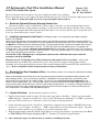
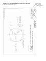
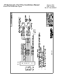
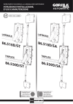
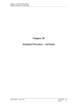
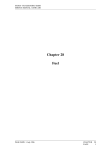
J.P.Instruments Fuel Flow Installation Manual
for EGT-701 with Fuel Flow Option
Report # 503
Page 1 of 14
Rev B : Date 03/14/97
Table of Contents
1.
2.
3.
4.
5.
6.
7.
8.
9.
10.
11.
12.
13.
14.
15.
General
Initial Check Out
Installing the Fuel Flow Transducer
Route the Optional warning control line
Install the instrument in the panel
Route the Fuel Flow Transducer Wires
System Checkout
Specifications and Limitations
Pilot Programmable Modes
Drawing 700923
Drawing 700922
Drawing 700921
Drawing 700124 (excerpt from report #103, STC 2586NM)
Drawing 700744 (excerpt from report 103, STC 2586NM)
Drawing 700920 Installing the Fuel Flow Differential
Module FFDM-1 or FFDM-2
J.P.INSTRUMENTS
PO BOX 7033
HUNTINGTON BEACH CA 92704
Last printed 8/7/2008 1:58:00 PM
2
3
4
5
5
5
5
6
7
8
9
10
11
12
13,14
J.P.Instruments Fuel Flow Installation Manual
for EGT-701 with Fuel Flow Option
Report # 503
Page 2 of 14
Rev B : Date 03/14/97
EGT-701 with Fuel Flow Option
Installation Instructions
1…General:
A complete thorough familiarization and understanding of the system and this manual is necessary before commencing
the installation. All work must conform with A.C. 43.13.1A ch. 11 sec. 2, 3, 7. The accuracy of this instrument
depends entirely upon the accuracy of the data entered. A periodical checking of the actual fuel onboard will eliminate
the accumulation of errors due to evaporation leaks, etc.
Do not use the FXT-201 Flow Transducer on aircraft with a gravity feed system. The standard Fuel
Transducer (FXT-201) shipped with the EGT-701(),with Fuel Flow option Fuel Flow instrument is intended to be used
on aircraft equipped with fuel pumps. A gravity feed system requires the FXT-231 flow transducer.
Transducer Identification Markings
FXT-201 - Marked "20 l " on the top of the unit.
FXT-231 - Marked "231" on the top of the unit.
Installation of the EGT-701(),with Fuel Flow option on an aircraft with a fuel return line from the Carburetor
requires a FFDM-1, -2 Differential Module manufactured by from EI or JPI.
The placard "Do Not Rely on Fuel Flow Instrument to Determine Fuel Levels in Tanks" must be mounted on the
aircraft instrument panel near the EGT-701, ( ) with fuel flow option.
If the aircraft is equipped with a primary fuel flow, the following placard must be mounted on the aircraft
instrument panel near the EGT-701(),WITH FUEL FLOW OPTION( ): "Refer to Original Fuel Flow
Instrumentation for Primary Information".
do not obstruct the freedom of travel of arty controls.
J.P.Instruments Fuel Flow Installation Manual
for EGT-701 with Fuel Flow Option
Report # 503
Page 3 of 14
Rev B : Date 03/14/97
2…. Initial Check Out
1. The aircraft owner must read the Warranty before starting the installation. There is information in the Warranty that
may alter your decision to install this instrument. If you do not accept the terms of the Warranty, JPI offers a 30
day money back guarantee.
2. If you are not an FAA Certified Aircraft Mechanic familiar with the issues of installing aircraft fuel flow, Do
Not attempt to install this instrument. The installer should use current aircraft standards and practices to install
this instrument (refer to AC 43.13).
3. Check that any necessary FAA Approvals (STC's, etc.) are available for your aircraft before starting the
installation. The FAA Approved Model List (AML) is located at the back of this manual.
4. Read the entire Installation Instructions and resolve any issues you may have before starting the installation.
5. THIS INSTALLATION WILL REQUIRE SOME PARTS UNIQUE TO YOUR AIRCRAFT THAT ARE
NOT SUPPLIED IN THE KIT (including, but not limited to hoses and fittings). Acquire all the parts necessary
to install this instrument before starting the installation. Do not use aluminum fittings with the FXT-201 or FXT-231
transducer.
6. Check that the instrument make and model are correct before starting the installation (check the markings on the side
of the instrument). A gravity feed system requires an FXT-231 flow transducer (marked "231" on top). A carbureted
engine with a fuel return line requires an FFDM-I, -2 , which can be purchased from Electronics International, or
J.P.Instruments.
7. Before starting the installation make sure the unit will fit in the location you intend using. Refer to J.P.Instruments
installation report 103, for the EGT-701, temperature indicator , STC SA 2586NM.
8. If this instrument is to replace an existing unit in the aircraft, it is the installer's responsibility to move or replace any
existing instruments or components in accordance with FAA approved methods and procedures. The following
Installation Instructions do not cover moving or the removal of any existing instruments or components.
9. Before connecting any hoses to the transducer, thoroughly clean them and insure they are free of any loose material.
Never pass high pressure air through or blow through the transducer, damage will occur.
10. Remove the transducer cap plugs when ready to install hoses. Do not use aluminum fittings with the fuel flow
transducer or Gauling may occur.
11. Note the direction of fuel flow marked on the transducer. Fuel must flow in this direction.
12. Mount the transducer with the three wires pointing up.
13. Note and record the K-factor engraved in the side of the transducer.
14. Do not use teflon tape or thread sealent compound of any kind.
J.P.Instruments Fuel Flow Installation Manual
Report # 503
Page 4 of 14
Rev B : Date 03/14/97
for EGT-701 with Fuel Flow Option
3…. Installing the Fuel Flow Transducer:
Mount the Fuel Flow Transducer using the appropriate drawing at the back of this manual.
Aircraft Configuration
Drawing #
Location
Page
1. All gravity Flow installations without fuel pump. Must use
FXT-231
2. All Fuel injected engines with vapor return lines to fuel tank , all
Continental and certain Lycoming engines.
700923
Between Fuel tank and
Carburetor.
8
700922
Between throttle body
and fuel flow divider.
9
3. All pump fed carbureted and Fuel injected engines without
vapor return lines.
700921
Between engine driven
pump and servo/throttle
body or carburetor
10
4. Pressure Carbureted engines with vapor return lines
700923
700920
One transducer in Carb
inlet line and one
transducer in out let line
8, 11,
12
The instructions listed below must be followed when installing a Fuel Flow Transducer.
Note: If your engine is equipped with a fuel return line from the carburetor back to the fuel tank you will need to install two
flow transducers... one in the feed line from the fuel pump to the carburetor and one in the return line from the carburetor back
to the fuel tank. Also, a Fuel Flow Differential Module (Dwg. 700920) will need to be installed.
The transducer output port should be mounted lower or even with the carburetor inlet port (or fuel servo on a fuel injected
engine). If this is not possible, a loop should be put in the fuel line between the Fuel Flow Transducer and the carburetor or fuel
servo (see diagram below).
Do not remove the caps on the flow transducer until the fuel hoses are ready to be installed.
The flow of fuel through the transducer must follow the direction marked on the transducer.
If the transducer is higher
than the carburetor or fuel
servo, put a loop in the fuel
line between the transducer
and the carburetor or fuel
sevo.
Mount the
transducer
with the
wires up.
SIDE VIEW
Carburetor or Servo
¼ NPT
END VIEW UP
The direction of the fuel
flow through the transducer
is marked on top
J.P.Instruments Fuel Flow Installation Manual
for EGT-701 with Fuel Flow Option
Report # 503
Page 5 of 14
Rev B : Date 03/14/97
The flow transducer must be mounted so the wires exiting the transducer are pointing up.
Before connecting any hoses, thoroughly clean them and insure they are free of any loose material. High air pressure my
be used, However, do not allow high air pressure to pass through the flow transducer.
4…. Route the (Optional) External Warning Control Line:
The wire from pin 12 on the J-1 (D-SUB 25) Connector can be connected to an external warning light or buzzer.
This wire grounds when the display flashing a warning is on. The current in this line must be limited to 2/10 of an amp
maximum. Exceeding this limit will damage the unit. If this feature is not used leave this line open. Tie wrap this wire so
it does not obstruct the freedom of travel- controls.
5…. Install the Instrument in the Panel:(The following section is an excerpt from report #103 Installation
Manual, STC 2586NM)
Locate a 2.25 diameter hole in the instrument panel, where you would like to mount the indicator per drawing 700124. A
steel template supplied with the installation kit is used as a guide for drilling two button holes in the instrument panel. Align
and Mount the Template into the instrument panel hole. First drilling a 0.125 hole. Remove the template and check the
instrument alignment, if OK redrill with a 0.147 drill. The EGT-701(),with Fuel Flow option mounts in a standard 2.25"
instrument hole. The instrument configures itself automatically for 4 to 9 cylinder, 14/28 volt aircraft. The instrument is
7.5” deep less connectors and is 2.6 square behind the panel. To prevent display damage it is essential that the mounting
screws not penetrate the bezel more than .12 inches.
The indicator is FAA TSO approved, as a temperature indicator under TSO-C43b and must be installed in
accordance with STC SA2586NM.
Mount the placard "Do Not Rely on Fuel Flow Instrument to Determine Fuel Levels in Tanks" on the aircraft
instrument panel near the EGT-701(), with fuel flow option. If the aircraft is equipped with a primary fuel flow
instrument, the following placard must be mounted on the aircraft instrument panel near the EGT-701(),with Fuel Flow
option: "Refer to Original Fuel Flow Instrumentation for Primary Information".
6…. Route the Fuel Flow Transducer Wires: (The following section is an excerpt from report #103 Installation
Manual, STC 2586NM)
Route the thermocouple and fuel flow wires from the probes through the firewall using fireproof rubber grommets and
flame retarding silicone. Use an existing hole if possible. Following the existing wiring harness and connect to the
indicator marking each lead with the cylinder number. All wires must be routed away from high temperature areas
(exhaust stacks, turbochargers, etc.). Secure Probe leads to a convenient location on the engine approximately 8 to 12
inches from the probe, being sure there is sufficient slack to absorb engine torque. It is essential in routing the probe and
fuel flow transducer wires not be allowed to touch metal parts of the air-frame or engine since abrasion will destroy this
wire. Connect wires in accordance with dwg 700744, page 12
7….. System Checkout: Check instrument operation as follows:
1. Turn the aircraft master switch on (engine off) and set the toggle switch to Fuel Flow . Tap the step switch until 0
GPH is displayed. Turn the boost pump on for a few seconds. The display should indicate 3 to 8 GPH.. A problem at
this step could be caused by poor connections on the red or black power and ground leads.
2. Set the instrument toggle switch to "Fuel Flow" and check for a digital fuel flow reading of "00 GPH" indicates the
fuel flow is too low to register. A reading of “ ---GPH “ dashes indicate no fuel flow transducer signals. A problem
at this step could be caused by a poor connection or crossed flow transducer wires.
3. With the engine running, check the "FLOW" Display Mode to read properly. If there is a problem at this point Refer
to EDM-700 Fuel Flow Option Supplement Rev C. Section 4 for troubleshooting information.
4. After running the engine, check the fuel hoses, transducers and fittings for leaks.
J.P.Instruments Fuel Flow Installation Manual
for EGT-701 with Fuel Flow Option
8…
Report # 503
Page 6 of 14
Rev B : Date 03/14/97
Specifications and Limitations
Model:
EGT-701(), with Fuel Flow option
Case Dimensions:
2.5" x 2.5" x 7.5" depth, 2 1/4" Bezel.
Weight:
Unit Only:
Flow Transducer:
16 oz
3 oz
Environmental;
Passed TSO C43c and DO-178a (software level 3)
Power Requirements:
10 to 35 Volts, 2 Amp.
Low Fuel Warning Display
The display message will blink anytime the programmed Low Fuel Reminder, Low Fuel Warning or the Time to Empty
Limit are violated.
External Warning Control Line:
Grounds when any Warning display is on or blinking. Current should be limited to 2/10 amp.
Accuracy:
Flow:
Resolution
Fuel Flow:
Fuel Remaining:
Fuel Used:
Time to Empty:
2% or better in accordance with TSO C44a.
0.1 Gal. or 1 Lb. or .1 Ltr.
0.1 Gal. or 1 Lb. or . 1 Ltr.
0.1 Gal. or 1 Lb. or .1 Ltr.
10 minute
Max Displayed Range (Unit Only):
Fuel Flow:
Fuel Remaining:
Fuel Used:
Time to Empty:
199.9 Gals. or 162.0 or Gal/Hr or 1199 Lbs/Hr or 749 Ltr/Hr.
999 Gals. or 811 or Gals. or 1999 Lbs. or 1999 Ltrs.
999 Gals. or 811 or Gals. or 1999 Lbs. or 1999 Ltrs.
19 hours 59 minutes
J.P.Instruments Fuel Flow Installation Manual
for EGT-701 with Fuel Flow Option
Report # 503
Page 7 of 14
Rev B : Date 03/14/97
9… Pilot Programmable Modes: (excerpt from STC 2586NM)
See JPI Installation Manual For EGT-701, No 103 Page 8 for more information.
RS232/422 Input Ports (EGT-701(),with Fuel Flow option Only!:
Single Line Receive Method:
RS-232C, RS423, or 5 Volt Serial.
Dual Line Receive Method:
RS-422 or RS-485.
Protocol:
1 Start bit, 8 Data bits, 1 Stop bit.
Baud Rate:
L 1 = 9600, L 2 = 1200
Format:
Moving Map Output: L 1 = King KIN-88, L 2 = Northstar
RS232 Output Port
Transmit Method:
Protocol:
Baud Rate:
Transmit Format:
RS-232 Single Line.
1 Start bit, 8 Data bits, 1 Stop bit.
9600
King KIN-88.
Fuel Flow Transducer, Standard (FXT-201)
Fuel Flow Transducer, Gravity Only (FXT-231):
Range:
0.6 to 60 GPH
Linearity:
%1 (8 to 60 GPH)
K Factor
Approx. 29,000
Pressure Drop:
1.2 PSI at 30 GPH
4.8 PSI at 60 GPH
Working Press: 200 PSI
Min. Burst Press: 2000 PSI
Temp. Range: -65'C to 125'C
Fuel Ports: 1/4" Female NPT
Range:
3 to 90 GPH
Linearity:
%1 (8 to 60 GPH)
K Factor:
Approx. 19500
Pressure Drop:
.31 PSI at 30 GPH
2.8 PSI at 90 GPH
Working Press: 200 PSI
Min. Burst Press: 2000 PSI
Temp. Range: -65'C to 125'C
Fuel Ports: 1/4" Female NPT
J.P.Instruments Fuel Flow Installation Manual
for EGT-701 with Fuel Flow Option
Fuel line from
the Carburetor
To the Fuel Tank
8 inches
Maximum from
support
TRANSDUCER
Aeroquip Fire
Sleeve
AE102/62-24
To the Fuel Tank
Aeroquip
900591B
Clamp
Fuel IN
OUT
MS 21919 Clamp
as required
Report # 503
Page 8 of 14
Rev B : Date 03/14/97
Fittings ¼ NPT to Fuel
Hose (do not use
aluminum fittings
Aeroquip Fire sleeve
AE102/62-24
Mount to
Firewall or
Engine
Mounting Procedure:
1.
Find a convenient location within 8" of a hose support or fitting and away from any hot exhaust pipes to suspend the Fuel Flow
Transducer. The hose support or fitting may be on the input or output line of the Flow Transducer.
2.
Remove the fuel hose which goes from the Carburetor to the Fuel Tank.
3.
Purchase two new hoses, one from the Carburetor to the Fuel Flow Transducer and the other from the Fuel Flow Transducer to the
Fuel Tank. There must be flexible hose in and out of the Transducer. The hoses must meet TSO-C53a Type C or D FAA
specification. The new hoses must be the same diameter as the current hose in the aircraft.
4.
Mount the Fuel Flow Transducer in the fuel supply line and in the return line for pressure carburetors. The Flow Transducer
must be wrapped with Fire Sleeving. Place a small hole in the fire sleeve and pass the transducer wires through it. Seal with
High temperature Silicone RTV sealant.
5.
Before connecting fuel hose to the carburetor , verify that the boost pump delivers at least 125% of takeoff fuel consumption at
minimum fuel pressure as marked on fuel pressure gage.
J.P.INSTRUMENTS
PO Box 7033
Huntington Beach CA 92646
Title : Installation of a Fuel Flow Transducer in the fuel
supply or return line from the carburetor to the fuel tank
Drawing No.
700923
Date
Drawn/
Approved
Rev NC
02/14/97
J.P.Instruments Fuel Flow Installation Manual
for EGT-701 with Fuel Flow Option
Report # 503
Page 9 of 14
Rev B : Date 03/14/97
To the Flow Divider
OUT
Aeroquip
900591B Clamp
Mounting Procedure:
Fittings ¼ NPT to
Fuel Hose (do not
use aluminum
fittings
1. Find a convenient location between the Throttle Body and the Flow Divider and
away from any hot exhaust pipes to suspend the Fuel Flow Transducer.
2. Remove the fuel hose which goes from the Throttle Body to the Flow Divider.
3. Purchase two new hoses, one from the Fuel Servo to the Fuel Flow Transducer
and the other from the Fuel Flow Transducer to the Flow Divider. There must
be flexible hose in and out of the Fuel Transducer. The hoses must meet
TSO-C53a Type C or D FAA specification. The new hoses must be the same
size as the current hose in the aircraft. A source of fittings and fabricated
hoses is:
Aeroquip Fire
Sleeve
AE102/62-24
IN
Aeroquuip
303 hose
4. Mount the Fuel Flow Transducer in the fuel line. The Flow Transducer must
be wrapped with Fire Sleeving. Place a small hole in the fire sleeve and
See note 5
pass the transducer wires through it. Seal with High temperature Silicone From the Throttle Body
RTV sealant.
5. Secure at either end of the transducer to any convenient point on the engine with
MS21919 clamps or equivalent.
6. For Continental fuel injected engines adjust the fuel pressure to account for the pressure drop across the transducer
per Continental Service Bulletin M89-10
7. Cessna 182-T aircraft with an IO-540 engine must use the gravity 700900-2 Transducer if connecting between the
Throttle Body and the Flow Divider.
J.P.INSTRUMENTS
PO Box 7033
Huntington Beach CA 92646
Title Installation of the Fuel Flow Transducer in the fuel line
between the Throttle Body and the Flow Divider. Only applicable
for Continental Fuel Injected Engines
Drawing No. 700922
Date
Drawn/
Approved
Rev NC
02/14/97
J.P.Instruments Fuel Flow Installation Manual
Report # 503
Page 10 of 14
Rev B : Date 03/14/97
for EGT-701 with Fuel Flow Option
Fuel injector
Existing Fitting
TRANSDUCER
To Engine Driven Fuel
Pump Existing
MS21919 Clamp
as required
8" max from
support
Aeroquip
900591B Clamp
Aeroquip Fire Sleeve
AE102/624-24
2-AN816- Pipe to
Flare fitting. Do not
use aluminum fittings
New 303Aeroquip hose
Mounting Procedure:
1. Find a convenient location within 8" of a hose support or fitting and away from any hot exhaust pipes to suspend the Fuel Flow
Transducer. The hose support or fitting may be on the input or output line of the Flow Transducer.
2. Remove the fuel hose which goes from the Fuel Pump to the Carburetor (or Fuel Servo).
3. Purchase two new hoses, one from the fuel pump (or the Fuel Filter) to the Fuel Flow Transducer and the other from the Fuel Flow
Transducer to the carburetor (or fuel servo). There must be flexible hose in and out of the Transducer. The hoses must meet
TSO-C53a Type C or D FAA specification. The new hoses must be the same size as the current hose in the aircraft.
4. Mount the Fuel Flow Transducer in the fuel line. You must use the FXT-231 Fuel Flow Transducer on a gravity feed system.
The FXT-201 Transducer is marked "Model 231" on the top of the transducer. The Flow Transducer must be wrapped with
Fire Sleeving. Place a small hole in the fire sleeve and pass the transducer wires through it. Seal with High temperature Silicone
RTV sealant.
5. Before connecting fuel hose to the carburetor , verify that the boost pump delivers at least 125% of takeoff fuel consumption at
minimum fuel pressure as marked on fuel pressure gage.
J.P.INSTRUMENTS
PO Box 7033
Huntington Beach CA 92646
Title : Installation of a Fuel Flow Transducer in the fuel line from the
fuel pump to the carburetor or fuel servo.
Drawing No. 700921
Date
Drawn
Approved
Rev NC
02/14/97
J.P.Instruments Fuel Flow Installation Manual
for EGT-701 with Fuel Flow Option
Report # 503
Page 11 of 14
Rev B : Date 03/14/97
J.P.Instruments Fuel Flow Installation Manual
for EGT-701 with Fuel Flow Option
Report # 503
Page 12 of 14
Rev B : Date 03/14/97
J.P.Instruments Fuel Flow Installation Manual
Report # 503
Page 13 of 14
Rev B : Date 03/14/97
for EGT-701 with Fuel Flow Option
1
2
3
Fuel Flow differential Module (FFDM-1, -2 )
Used with carbureted engines with a Fuel
Return line (pressure carburetors).
Connect to 15 pin D-Sub
connector on the EDM700
Power not required
on the FFDM-2
taken from EDM700
J.P.INSTRUMENTS
PO Box 7033
Huntington Beach CA 92646
Title: FFDM-1 Interconnect Wiring Diagram
Drawing No. 700920
Date
Drawn
Approved
Sheet
Rev NC
02/14/97
1 of 2
J.P.Instruments Fuel Flow Installation Manual
for EGT-701 with Fuel Flow Option
Report # 503
Page 14 of 14
Rev B : Date 03/14/97
10.. Installing the Fuel Flow Differential Module FFDM-I and the FFDM-2:
If your engine is equipped with a fuel return line from the carburetor back to the fuel tank, install the FFDM-1 or
FFDM-2 in the aircraft as outlined below (see sheet one ). Otherwise, omit this step.
a) Connect the connector to the FFDM-I, -2
b) Install the FFDM-1, -2 under the instrument panel using two tie wraps on each end of the module to support it to
a wire bundle or bracket.
c) Only required on the FFDM-1. Route and connect the 3' red power lead to the 12 or 24 volt bus via a 1 amp
fuse. Route and connect the 3' black ground lead to the same ground used for the EGT-701(),with Fuel Flow
option.
d) Route and connect the 6' red, black and white leads marked "Feed" to the flow transducer installed in the fuel
line from the fuel pump to the carburetor.
e) Route and connect the 6' red, black and white leads marked "Return" to the flow transducer installed in the
return fuel line from the carburetor to the fuel tank.
f) Connect the red, black and white leads to the same color 6' leads from the EGT-701(),with Fuel Flow option.
Any excess wires can be rolled up and tie wrapped under the instrument panel. Tie wrap these wires so they do not
obstruct the freedom of travel of any controls.
J.P.INSTRUMENTS
PO Box 7033
Huntington Beach CA 92646
Title: FFDM-1 Interconnect Wiring Diagram
Drawing No. 700920
Date
Drawn
Approved
Sheet
Rev NC
02/14/97
2 of 2