1
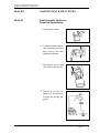
EXTRA - FLUGZEUGBAU GmbH SERVICE MANUAL EXTRA 200 Chapter 28 Fuel PAGE DATE: 1. July 1996 CHAPTER PAGE 28 1 EXTRA - FLUGZEUGBAU GmbH SERVICE MANUAL EXTRA 200 TABLE OF CONTENTS Chapter Title 28-00-00 GENERAL 28-01-00 28-01-01 28-01-02 28-10-00 ................................................................................................................ MAINTENANCE PRACTICES Refueling/Defueling Reduction of Fuel Tank Vapor Hazards ....................................................... ........................................................................................... STORAGE ........................................... ................................................................................................................. 28-11-00 28-11-01 28-11-02 28-11-03 28-11-04 28-11-05 28-11-06 28-11-07 28-11-08 MAINTENANCE PRACTICES Center and Acro Tank Removal/Installation Acro Tank Flop Tube Removal/Installation Wing Tank Inspection Door Removal/Installation Wing Tank Outlets Removal/Installation Center Tank Filler Neck Removal/Installation Wing Tank Filler Neck Removal/Installation Filler Neck Sealing Lip Replacement Ventilation Line Replacement 28-20-00 DISTRIBUTION 28-21-00 28-21-01 28-21-02 MAINTENANCE PRACTICES Fuel Selector Valve Removal/Installation Fuel Selector Valve Control Rod Removal/Installation Gascolator Removal/Installation Electrical Boost Pump Removal/Installation Fuel Line Replacement 28-21-03 28-21-04 28-21-05 28-40-00 28-41-00 28-41-01 28-41-02 28-41-03 28-41-04 28-41-05 PAGE DATE: 1. July 1996 3 5 5 5 7 9 9 10 11 12 13 13 14 14 ....................................................... ............................... ............................. ............. ................................... ...................... ......................... ............................................ ............................................................... ............................................................................................ ................................................... .................................. ...................................................................................... ........................................................ .......................... ................................................................................ INDICATING .................................................................................................... MAINTENANCE PRACTICES Fuel Quantity Indicator Removal/Installation Fuel Quantity Indicator Calibration (Center Tank) Tubular Tank Unit (Center Tank) Removal/Installation Lever-type Tank Unit (Wing Tank) Removal/Installation Float Wire Adjustment ................................................... ....................... ........... ...................................................................................... ...................................................................................... ................................................................................. CHAPTER PAGE 15 17 17 17 19 20 21 22 24 24 25 25 26 27 28 2 EXTRA - FLUGZEUGBAU GmbH SERVICE MANUAL EXTRA 200 28-00-00 GENERAL The fuel system (refer to Figure 1) consists of a center tank (3) with acro tank (5), two wing tanks (1), a fuel selector valve (2), a gascolator (8) , an electrically driven auxiliary pump (7) and an engine driven rotary pump (6). Concerning the fuel drains (4) also refer to Chapter 12-10-03. On the rear instrument panel one fuel quantity indicator for the center tank and one for the wing tanks, the switch/circuit breaker for the boost pump and the circuit breaker for the indication are installed. For fuel tank capacities refer to Chapter 12-10-01. PAGE DATE: 1. July 1996 CHAPTER PAGE 28 3 EXTRA - FLUGZEUGBAU GmbH SERVICE MANUAL EXTRA 200 GENERAL lö ösgsödfg dsfgdfg df sdf fg sdf sdfgs fdg s df s df sdfgsdfg sfdg s PAGE DATE: 1. July 1996 8 7 Gascolator Electric driven aux. pump Engine driven rotary pump 5 4 6 Acro tank Center tank 3 Drain Wing tank 2 1 Legend: Fuel System Figure 1 Selector valve dfg s dfg s dfg sdf sd CHAPTER PAGE 28 4 EXTRA - FLUGZEUGBAU GmbH SERVICE MANUAL EXTRA 200 28-01-00 MAINTENANCE PRACTICES 28-01-01 Refueling/Defueling Refer to Chapter 12 for detailed refueling/defueling procedures. 28-01-02 Reduction of Fuel Tank Vapor Hazards General Precautions During all ventilation or maintenance procedures involving the fuel system, observe the following general precautions. 1 Defueling should be outdoors with the aircraft at least 100 feet from hangars or other aircraft. 2 No smoking should be allowed within 100 feet of the aircraft. 3 Suitable fire fighting equipment should be available. Foam or soda type extinguishing agents are recommended. 4 Ground the aircraft to prevent static electricity from causing sparks. If a ramp ground is available it should be connected to exhaust stack. If a ramp ground is not provided, a temporary ground can be obtained by driving a metal rod into the ground and attaching a ground wire between the rod and the aircraft exhaust stack. 5 Flame and spark producing equipment should not be operated within 100 feet of the aircraft. 6 The aircraft should have its battery removed. 7 Only personnel working on the aircraft should be allowed in the immediate area, and no other maintenance should be performed while the tanks are being worked on. 8 When a fuel tank is opened for repair, air ventilation (refer to following Page) should be started immediately to reduce vapor concentrations. PAGE DATE: 1. July 1996 CHAPTER PAGE 28 5 EXTRA - FLUGZEUGBAU GmbH SERVICE MANUAL EXTRA 200 MAINTENANCE PRACTICES Reduction of Fuel Tank Vapor Hazards 9 When draining fuel, ensure that suitable containers are available and that drained fuel is stored safely. Do not allow fuel to drip to the ground and form pools. 10 If it is necessary to ventilate a tank when the aircraft is in hangar, ensure that vapors do not accumulate to explosive or toxic levels in the hangar. WARNING When fuel is being drained, there is little control over the release of fuel vapor. This vapor should be dissipated as quickly as possible. Compressed air or explosion-proof blowers may be used for the purpose. Air Ventilation 1 Completely drain the fuel system per Chapter 12-1002. 2 Remove inspection doors (refer to Chapter 28-11-03) and tank caps. 3 Use compressed air or an explosion-proof blower to blow air into the tank until tank interior is dry and free of vapor. 4 Continue ventilation whenever tank is open and being worked on. WARNING PAGE DATE: 1. July 1996 If flammable vapors from cleaning solvents are allowed in the tank increase air circulation to dissipate them. CHAPTER PAGE 28 6 EXTRA - FLUGZEUGBAU GmbH SERVICE MANUAL EXTRA 200 28-10-00 STORAGE The EXTRA 200 is equipped with two independent fuel systems: The center- and acro tank system and the wing tank system. The acro tank (1, Figure 2) incorporating an inverted flight fuel supply system is connected to the center tank (2) which is mounted in front of the main spar. Fueling the center and acro tank is by means of the fuselage 2" diameter filler cap (5). For leak detection the center and acro tank are furnished with a GRP tank shell. In case of leakage blue colored fuel is shining through. The center/acro tank is grounded. The center and acro tank deaerate by ventilation tubes (a-b) ending at the right side of the main landing gear spring. The root section of each wing in front of the main spars forms an integral fuel tank of approximately 100 cm (39") length (4). Each wing tank has a 2" diameter filler cap (5) for gravity fueling. Sealing lips are installed at the filler necks inside the wingtank. For sealing 3M Brand Fuel Resistant Coating 776 (3M, St. Paul, USA) has been applied to the inside of the wing tanks. For lightning protection reason the shell in the area of the wing tank has an outer layer of carbon fiber with incorporated aluminium thread (3). The wing tanks are grounded. Each tank is provided with an alu ventilation tube (c) for adequate venting. The ventilation tubes are interconnected to a main tube (d), ending outside of the fuselage at the right side of the main landing gear spring. PAGE DATE: 1. July 1996 CHAPTER PAGE 28 7 EXTRA - FLUGZEUGBAU GmbH SERVICE MANUAL EXTRA 200 PAGE DATE: 1. July 1996 Ventilation lines a-d 5 4 Filler cap Wing tank Lightning strike protection layer 3 2 Center tank Acro tank Legend: Storage Figure 2 1 STORAGE CHAPTER PAGE 28 8 EXTRA - FLUGZEUGBAU GmbH SERVICE MANUAL EXTRA 200 28-11-00 MAINTENANCE PRACTICES 28-11-01 Center and Acro Tank Removal/Installation 1 Remove the main fuselage cover (refer to Chapter 51). 2 Drain the fuel system per Chapter 12-10-02. 3 Loosen the electrical facilities and remove hose fixtures. 4 Loosen and remove the metal attachment belts with the rubber stripes. 5 Remove the center/acro tank to the top. 6 Install in reverse sequence of removal. PAGE DATE: 1. July 1996 CHAPTER PAGE 28 9 EXTRA - FLUGZEUGBAU GmbH SERVICE MANUAL EXTRA 200 28-11-02 MAINTENANCE PRACTICES Acro Tank Flop Tube Removal/Installation 1 Drain the fuel system per Chapter 12-10-02. 2 Disconnect the hose (5, Figure 3) and the elbow fitting (4). 3 Loosen the flop tube fitting (3) and take the flop tube assembly (2) out of the acro tank (1). WARNING Stripping solvents can be toxic and volatile. Use only in well ventilated areas. Avoid physical contact with solvent and do not inhale vapors. Keep solvent containers covered when not in use. 4 Clean the sealing surfaces mechanically and with Acetone. NOTE If the flop tube assembly has to be replaced install a complete new assembly. 5 Install in reverse sequence of removal after applying Loctite 577 to the flop tube fitting thread. Flop Tube Removal/Installation Figure 3 15.July December PAGE DATE: 1. 1996 1999 CHAPTER PAGE 28 10 EXTRA - FLUGZEUGBAU GmbH SERVICE MANUAL EXTRA 200 28-11-03 MAINTENANCE PRACTICES Wing Tank Inspection Door Removal/Installation 1 Drain the fuel system per Chapter 12-10-02. 2 Disconnect the ground bonding leads and if necessary (LH wing tank) the electrical wiring of the lever-type tank unit (3, Figure 4). 3 Remove the inspection door bolts. 4 Remove the inspection door flange (1). 5 Push the inspection door (2) into the tank, then turn and remove. WARNING Stripping solvents can be toxic and volatile. Use only in well ventilated areas. Avoid physical contact with solvent and do not inhale vapors. Keep solvent containers covered when not in use. 6 Clean the sealing surfaces mechanically and with Acetone. 7 Install in reverse sequence of removal after applying 3M Brand Fuel Resistant Coating 776 (3M, St. Paul, USA) to the sealing surfaces (inspection door and tank root rib). Inspection Door Removal/Installation Figure 4 PAGE DATE: 1. July 1996 CHAPTER PAGE 28 11 EXTRA - FLUGZEUGBAU GmbH SERVICE MANUAL EXTRA 200 28-11-04 MAINTENANCE PRACTICES Wing Tank Outlets Removal/Installation 1 Remove the inspection door (1) (refer to Figure 5) per Chapter 28-11-04. 2 Remove the union nuts (2) and the elbow tubes (3). 3 Remove AN 924 nut and washers and remove AN 832 fitting. WARNING Stripping solvents can be toxic and volatile. Use only in well ventilated areas. Avoid physical contact with solvent and do not inhale vapors. Keep solvent containers covered when not in use. 4 Clean sealing surfaces mechanically and with Acetone. 5 Install in reverse sequence of removal after applying 3M Brand Fuel Resistant Coating 776 (3M, St. Paul, USA) to the sealing surfaces (fitting to tank root rib). Ensure that the outlet end positions are in the upperresp. undermost edge of the wing tank (see Figure 7 below). Wing Tank Outlets Removal/Installation Figure 5 15.July December PAGE DATE: 1. 1996 1999 CHAPTER PAGE 28 12 EXTRA - FLUGZEUGBAU GmbH SERVICE MANUAL EXTRA 200 28-11-05 MAINTENANCE PRACTICES Center Tank Filler Neck Removal/Installation 1 Remove the main fuselage cover per Chapter 51. 2 Completely drain the fuel system per Chapter 12. 3 Loosen the lower hose clip. 4 Remove the filler neck. 5 Install in reverse sequence of removal. 28-11-06 Wing Tank Filler Neck Removal/Installation 1 Completely drain the fuel system per Chapter 12. 2 Remove wing tank inspection door per Chapter 28-1103. 3 Unscrew filler neck lock ring (4, Figure 6) with sealing lip (5) using a tool as shown in Figure 6. 4 Remove filler neck (3) with filler cap (1) and O-ring (2). WARNING Stripping solvents can be toxic and volatile. Use only in well ventilated areas. Avoid physical contact with solvent and do not inhale vapors. Keep solvent containers covered when not in use. 5 Clean all sealing surfaces with Acetone. 6 Install in reverse sequence of removal after applying 3M Brand Fuel Resistant Coating 776 (3M, St. Paul, USA) to the sealing surfaces (wing/filler neck). PAGE DATE: 1. July 1996 CHAPTER PAGE 28 13 EXTRA - FLUGZEUGBAU GmbH SERVICE MANUAL EXTRA 200 28-11-07 MAINTENANCE PRACTICES Filler Neck Sealing Lip Replacement Filler Neck Sealing Lip Replacement 1 Carefully drill out the body-bound rivets (7, Figure 6). 2 Install the new sealing lip driving in new washers (6) and body-bound rivets. Filler Neck and Sealing Lip Removal/Installation Figure 6 28-11-08 Ventilation Line Replacement Refer to Figure 6A. Small letters (a-c) refer to the marks of Figure 2. General information concerning hoses and fittings you find in Chapter 20. NOTE PAGE DATE: 1. July 1996 Use only, tubes and fittings as listed in the following. CHAPTER PAGE 28 14 EXTRA - FLUGZEUGBAU GmbH SERVICE MANUAL EXTRA 200 28-20-00 DISTRIBUTION (Refer to Figure 7) Flexible hoses and aluminium tubes (A-J) connect the particular components of the fuel system. From Serial No. 25 the drain line "K" has been added. In addition to the engine driven fuel pump (4), an electrically driven auxiliary pump (5) having sufficient capacity to feed the engine at take-off power is fitted as a safety device against failure of the engine driven pump. The auxiliary pump switch/circuit breaker is located on the rear instrument panel. A gascolator (6) is installed between the fuel selector valve and the auxiliary fuel pump at the firewall (engine side). A fuel selector valve of an Allen 6S122 type (1) is located at the right side of the front cockpit behind the main spar on a separate support. A control rod connects the selector valve to the control handles (2). The fuel selector valve is marked by the letters "WT" (Wing Tank), "E" (Engine), and "CT" (Center Tank) to ensure correct installation of fuel lines (Refer to "Detail A" of Figure 8). The two tank systems are equipped with separate drain lines. Drains (3) are located at the gascolator and the left and right side of the bottom fuselage. PAGE DATE: 1. 15.July December 1996 1999 CHAPTER PAGE 28 15 Distribution Figure 7 1996 1999 PAGE DATE: 1. 15.July December Drain A-K 6 5 4 Fuel lines Gascolator Electric driven aux. pump Engine driven rotary pump Control rod and handles 3 2 Fuel selector valve 1 Legend: EXTRA - FLUGZEUGBAU GmbH SERVICE MANUAL EXTRA 200 DISTRIBUTION CHAPTER PAGE 28 16 EXTRA - FLUGZEUGBAU GmbH SERVICE MANUAL EXTRA 200 28-21-00 MAINTENANCE PRACTICES 28-21-01 Fuel Selector Valve Removal/Installation 1 Drain the fuel system per Chapter 12-10-02. 2 Disconnect the fuel lines on the selector valve. 3 Remove the control rod attachment bolts (5, Figure 8). 4 Remove the selector valve attachment bolts (2). 5 Remove the selector valve (1). 6 Install in reverse sequence of removal. Use LOCTITE when installing the selector valve attachment bolts. 28-21-02 Fuel Selector Valve Control Rod Removal/Installation 1 Remove the rear control rod connection bolt (11, Figure 8). 2 Remove the rear control rod (12) to the rear. 3 Loosen the bolt of the adjusting ring (8). 4 Remove the front control rod connection bolt (7). 5 Remove the middle control rod (10), the adjusting ring (8) and the spring (9) to the rear. 6 Remove the control rod attachment bolts (5). 7 Remove the front control rod (6) . 8 Install in reverse sequence of removal. Consider that the position of the adjusting ring shall give the spring enough tension to move the control rod into the foremost position after having tied back. PAGE DATE: 1. July 1996 CHAPTER PAGE 28 17 EXTRA - FLUGZEUGBAU GmbH SERVICE MANUAL EXTRA 200 MAINTENANCE PRACTICES lö ösgsödfg dsfgdfg df sdf fg sdf sdfgs fdg s df s df sdfgsdfg sfdg s Rear control rod with handle 12 Rear control rod connection bolt Middle control rod with handle 10 Spring Adjusting ring and bolt Front control rod connection bolt Front Control rod Control rod attachment bolts Control handle 3 sdfgs Selector valve sdfgsdfg 1 sdfgsfdg Control handle attachment screw sdfgsfdgsdfg Selector valve attachment bolts dfg s dfg s 11 9 8 7 6 5 4 2 Legend: sfdgggggggggggggggggggggggggggggggggggggggggggggggggggggggdfg sdf sd Fuel Selector Valve and Control Rod Figure 8 PAGE DATE: 1. July 1996 CHAPTER PAGE 28 18 EXTRA - FLUGZEUGBAU GmbH SERVICE MANUAL EXTRA 200 28-21-03 MAINTENANCE PRACTICES Gascolator Removal/Installation 1 Drain the fuel system per Chapter 12-10-02. 2 Disconnect the fuel lines on the gascolator. 3 Loosen the knurled nut (1, Figure 9). 4 Remove the mounting bracket (2). 5 Remove the fuel reservoir (3) and the sealing ring (4). 6 Remove the strainer (5) and the gascolator cover (6). 7 Install in reverse sequence of removal. Gascolator Removal/Installation Figure 9 PAGE DATE: 1. July 1996 CHAPTER PAGE 28 19 EXTRA - FLUGZEUGBAU GmbH SERVICE MANUAL EXTRA 200 28-21-04 MAINTENANCE PRACTICES Electrical Boost Pump Removal/Installation 1 Drain the fuel system per Chapter 12-10-02. 2 Disconnect the plug and the fuel lines on the boost pump. 3 Loosen the clamping device screws (1, Figure 10). 4 Remove the boost pump (2). 5 Install in reverse sequence of removal. Boost Pump Removal/Installation Figure 10 PAGE DATE: 1. July 1996 CHAPTER PAGE 28 20 EXTRA - FLUGZEUGBAU GmbH SERVICE MANUAL EXTRA 200 28-21-05 MAINTENANCE PRACTICES Fuel Line Replacement Refer to Figure 10A. The letters (A-J) refer to the markings of Figure 7. General information concerning hoses and fittings you find in Chapter 20. IMPORTANT NOTE PAGE DATE: 1. July 1996 If replacement of fuel lines passing the firewall is necessary, renew the sealing of the rubber grommet grooves and gaps at the engine side of the firewall. Use PRC812 (Products Research & Chemical Corporation, USA) firewall sealant. Cover the fuel lines of the engine department with AEROQUIP AE102 fire sleeves as per Chapter 20-10-07. Use only, tubes and fittings as listed in the following. CHAPTER PAGE 28 21 EXTRA - FLUGZEUGBAU GmbH SERVICE MANUAL EXTRA 200 28-40-00 INDICATING (Refer to Figure 11) For fuel contents indicating the center tank is equipped with a tubular tank unit (1) and the left wing tank with a lever-type tank unit (2). They transmit the fuel levels to the respective fuel quantity indicators at the instrument panel (3). In contrast to the fuel quantity indicator of the center tank the one in the wing tank is not adjustable. If the indication is inexact the float wire of the tank unit has to be adjusted (refer to Chapter 28-41-05). PAGE DATE: 1. July 1996 CHAPTER PAGE 28 22 Indicating Figure 11 PAGE DATE: 1. July 1996 fuel quantity indicators 3 2 lever-type tank unit tubular tank unit 1 INDICATING Legend: EXTRA - FLUGZEUGBAU GmbH SERVICE MANUAL EXTRA 200 CHAPTER PAGE 28 23 EXTRA - FLUGZEUGBAU GmbH SERVICE MANUAL EXTRA 200 28-41-00 MAINTENANCE PRACTICES 28-41-01 Fuel Quantity Indicator Removal/Installation 1 Disconnect battery. 2 Loosen the nuts, remove the mounting bracket and remove the fuel quantity indicator. 3 Disconnect the wiring (the lamp is not used). 4 Install in reverse sequence of removal observing the wiring diagram. PAGE DATE: 1. July 1996 CHAPTER PAGE 28 24 EXTRA - FLUGZEUGBAU GmbH SERVICE MANUAL EXTRA 200 28-41-02 MAINTENANCE PRACTICES Fuel Quantity Indicator Calibration (Center Tank) 1 Drain the fuel system (refer to Chapter 12-10-02). 2 Remove the fuel quantity indicator following step 2 of Chapter 28-41-01. 3 Bring indicator to 0position by turning the adjustment screw. 4 Reinstall the fuel quantity indicator. 28-41-03 Tubular Tank Unit (Center Tank) Removal/Installation 1 Drain the fuel system per Chapter 12-10-02. 2 Loosen one bolt and replace by a M5 threaded rod (1) for securing the slotted retainer ring (2). 3 Remove the other bolts and the ground bonding lead (3). 4 Lift tubular tank unit and sealing ring over the threaded rod. 5 Remove the threaded rod and turn out the slotted retainer ring (2). WARNING PAGE DATE: 1. July 1996 Stripping solvents can be toxic and volatile. Use only in well ventilated areas. Avoid physical contact with solvent and do not inhale vapors. Keep solvent containers covered when not in use. CHAPTER PAGE 28 25 EXTRA - FLUGZEUGBAU GmbH SERVICE MANUAL EXTRA 200 MAINTENANCE PRACTICES 6 Clean sealing surfaces mechanically and with Acetone. 7 Install in reverse sequence of removal after applying 3M Brand Fuel Resistant Coating 776 (3M, St. Paul, USA) for sealing to both sides of the sealing ring. 28-41-04 Lever-type Tank Unit (Wing Tank) Removal/Installation 1 Disconnect the electrical wiring. 2 Remove LH inspection door (refer to Chapter 28-1103) 3 Remove tank unit bolts (1, Figure 12). 4 Remove the retainer ring (3) the tank unit (4) and the sealing ring (2). Lever-type Tank Unit (Wing Tank) Removal/Installation Figure 12 WARNING Stripping solvents can be toxic and volatile. Use only in well ventilated areas. Avoid physical contact with solvent and do not inhale vapors. Keep solvent containers covered when not in use. 5 Clean sealing surfaces mechanically and with Acetone. 6 Install in reverse sequence of removal after applying 3M Brand Fuel Resistant Coating 776 (3M, St. Paul, PAGE DATE: 1. July 1996 CHAPTER PAGE 28 26 EXTRA - FLUGZEUGBAU GmbH SERVICE MANUAL EXTRA 200 MAINTENANCE PRACTICES USA) for sealing to both sides of the sealing ring and the grooves inside the tank.. 28-41-05 Float Wire Adjustment 1 Remove the lever-type tank unit per Chapter 28-41-04. 2 Remove the float wire and bend it in form like shown in the following Figure 13: Float Wire Adjustment Figure 13 3 Reinstall the float wire observing the distances shown in Figure 14, pay attention to a proper alignment and tighten well the attachment bolt. Float Wire Installation Figure 14 4 Reinstall the lever-type tank unit per Chapter 28-41-04. PAGE DATE: 1. July 1996 CHAPTER PAGE 28 27 EXTRA - FLUGZEUGBAU GmbH SERVICE MANUAL EXTRA 200 MAINTENANCE PRACTICES Acro tank to main landing gear spring connection (a) Fittings and washers 1 AN816-4D PN: PC-00159 2 AN818-4D PN: PC-00161 Center tank to main landing gear spring connection (b) 3 AN818-6D PN: PC-00160 4 AN819-4D PN: PC-00860 5 AN819-6D PN: PC-00162 6 AN824-6D PN: PC-00168 Wing tank to wing tank connection (c) 7 AN832-6D PN: PC-00170 8 AN894-6-4D PN: PC-00154 9 AN924-6D PN: PC-00177 10 AN960-C916 PN: PC-01852 11 AN822-4D PN: PC-00155 Tubes 30 strainer tube PN: PC-63202.2 31 alu tube 5052-0, Ø3/8 inch PN: PC-00122 32 alu tube 5052-0, Ø1/4 inch PN: PC-00123 33 vinyl tubing PN: PC-01607 Tee-fitting to main landing gear spring connection (d) Ventilation lines Figure 6A PAGE DATE: 1. July 1996 CHAPTER CHAPTER 28 PAGE PAGE 14A 28 EXTRA - FLUGZEUGBAU GmbH SERVICE MANUAL EXTRA 200 MAINTENANCE PRACTICES Acro tank to selector valve connection (A) Acro/center tank drain (B) Wing tank to Tee-fitting connection (C) Tee-fitting to selector valve connection (D) Wing tank to Tee fitting connection (drain line) (E) Fittings and washers 1 AN491-4D PN: PC-00149 2 AN491-6D PN: PC-00150 4 AN816-4D PN: PC-00159 6 AN818-4D PN: PC-00161 7 AN818-6D PN: PC-00160 8 AN819-4D PN: PC-00860 9 AN819-6D PN: PC-00162 10 AN821-4D PN: PC-02630 11 AN821-6D PN: PC-02631 12 AN822-6D PN: PC-00164 13 AN823-6D PN: PC-00166 15 AN832-4D PN: PC-00171 16 AN832-6D PN: PC-00170 18 AN834-4D PN: PC-01644 19 AN834-6D PN: PC-00991 22 AN916-1D PN: PC-00180 23 AN924-4D PN: PC-00178 24 AN924-6D PN: PC-00177 25 AN960C-716 PN: PC-00810 26 AN960-C916 PN: PC-01852 27 O-ring MS29512-06 PN: PC-01270 28 O-ring MS29512-04 PN: PC-02632 Hoses* 30 AEROQUIP 303-4 PN: PC-00402 31 AEROQUIP 303-6 PN: PC-00403 Tubes 40 alu tube 5052-0, Ø1/4 inch PN: PC-00123 42 strainer tube PN: PC-64202.4 43 strainer tube PN: PC-64202.2 * Refer to Ch. 20-10-07 PAGE DATE: 1. July 1996 Fuel Lines Airframe Department Figure 10A, Sheet 1 Valves 50 drain valve PN: PC-01211 CHAPTER CHAPTER 28 PAGE PAGE 21A 29 MAINTENANCE PRACTICES EXTRA - FLUGZEUGBAU GmbH SERVICE MANUAL EXTRA 200 Wing tank drain assembly (drain line) (F) Selector valve to gascolator (G) Gascolator drain assembly (H) Fittings and washers 2 AN491-6D PN: PC-00150 4 AN816-4D PN: PC-00159 5 AN816-6D PN: PC-00158 6 AN818-4D PN: PC-00161 8 AN819-4D PN: PC-00860 11 AN822-6D PN: PC-00164 12 AN822-6D PN: PC-00164 17 AN833-6D PN: PC-00172 20 AN837-6D PN: PC-02858 21 AN912-9D PN: PC-00176 22 AN916-1D PN: PC-00180 24 AN924-6D PN: PC-00177 27 O-ring MS29512-06 PN: PC-01270 Hoses * 31 AEROQUIP 303-6 PN: PC-00403 Gascolator to boost pump connection (I) Tubes 40 alu tube 5052-0, Ø1/4 inch PN: PC-00123 Valves 50 drain valve PN: PC-01211 Boost pump to engine driven fuel pump connection (J) * Refer to Ch. 20-10-07 PAGE DATE: 1. July 1996 Fuel Lines Airframe Department Figure 10A, Sheet 2 CHAPTER CHAPTER 28 PAGE PAGE 21B 30


![[UK] Saver NG Data Sheets A1-2013](http://vs1.manualzilla.com/store/data/005759312_1-088a9b2c9a495b4ddfffe35115070dd1-150x150.png)